timgunn1962
Members
-
Joined
-
Last visited
Everything posted by timgunn1962
-
You have a blown burner, so you can control the temperature by varying the mixture. Leave the air where it is happy and increase the gas. If you richen up the mixture significantly, the flame temperature will reduce. If you richen it up enough, you can get it down to HT temperatures and this will allow long soak times at optimum temperature. You'll use a lot of gas and you'll need to run it outside, since the rich mixture will produce a huge amount of Carbon Monoxide (and death really doesn't improve your knifemaking). You'll need to reduce the size of the openings too. If you don't, the hot exhaust gases will flow out at the top and draw air in at the bottom. This extra air will cause the temperature to increase. As the mixture gets richer, the flame speed will get lower and the likelihood of a backfire due to the flamefront travelling through the burner block will reduce. As the flame temperature comes down, the heat input to the hot face of the block will come down and the likelihood of a flashback due to the back of the block reaching autoignition temperature will reduce. By keeping the airflow relatively high, and increasing the gas flow to get a cool-burning mixture, you will keep the cooling mixture flow through the burner block high and keep the probability of a flashback low. The extremely rich mixture will help to prevent scaling in the forge and may even help to reduce decarb. If you try this, use a thermocouple and do it outside. The thermocouple is mainly because judging temperature by eye outside is unlikely to give good results and the do it outside part is non-negotiable. Ribbon burners are very good for certain things, but they are not a magic bullet. Their biggest advantage is that they give short flames. To a large extent, flames are scalable. If you have a particular mixture composition and a particular mixture velocity, your flame will be X times as long as the diameter of your burner port. If we take an X of 4 (purely as an example), we could use a 2" single burner and produce a flame 8" long. Alternatively, we could put the same amount of the same mixture through a multi-port burner (ribbon burner) with 28 holes, each 3/8" in diameter and produce flames 1 1/2" long with the same burner port velocity. It is much easier to build a reasonably small forge that keeps the unburned mixture away from the workpiece if we only need an inch and a half to complete the burn and this is the main reason ribbon burners are used. Heat-treatment requires much less heat input than welding, or even forging. I have built forges (using commercial Venturi mixers) that can do everything from HT to welding in a single forge, but I really would not recommend it. For the same time, effort and money, I can build a conventional forging/welding forge and a dedicated HT forge, transferring the burner between them, and get much better performance. For the extra cost of a second, smaller, burner , the HT forge can be made to work very well indeed. I have built several electric HT ovens and am convinced the HT forges are better for a hobby knifemaker working in Carbon steels. The electric ovens are undoubtedly better for stainless steels, particularly those that benefit from ramp/soak programs. They need less attention in use, so are better for the professional as well. For the hobby maker though, the reduction in scaling (and maybe decarb) with the forge is a definite advantage. For my purpose-built HT forges, I normally use a 1/2" burner in an 8" diameter, 20"-22" long chamber and it is ample. The chamber is a 2-foot long 10" thinwall pipe lined with 1" of kaowool and has 1" kaowool board disks pushed in for the ends.
-
It doesn’t need to be expensive, or pretty, to make it finely-adjustable. A sliding gate will work and a couple of bent-up tabs of sheet metal on it can be enough to make things progressively adjustable with a long 1/4” screw.
-
You beat me to it. I was just about to post that if you are adding a couple of 90-degree bends and some extra pipe length to get the blower below the forge, do it in the larger bore pipe, not the smaller bore stuff. Looking at your blower, it seems to have about a 2" discharge. This reduces to 1" (maybe even 3/4") just downstream of the gas inlet. 1" pipe has 1/4 the area of 2" pipe and forcing air along 1" pipe takes much more pressure than forcing it along 2" pipe. Because of the way blower capacity tends to be quoted (maximum flow at zero pressure differential), you will have reduced your blower from a 75 CFM to a 19 CFM unit by reducing the area. This is not a problem since it is enough air to burn between 5.8 and 8.3 lb/hr of Propane: 5.8 lb/hr to Carbon Dioxide, 8.3 lb/hr to Carbon Monoxide. We tend to run rich (reducing) forge atmospheres with a mixture of CO2 and CO, so would burn somewhere reasonably near 7 lb/hr unless you have a way to reduce the air flow. The extra elbows and 1" pipe length will probably help to reduce gas flow and if that is 3/4" pipe you have used for the burner, you'll effectively have a 10.6 CFM blower able to burn between 3.2 and 4.7 lb/hr of Propane. It's still worth fitting either a globe valve or a sliding gate to bring the consumption down. If you can give it a threaded adjustment, you'll get much finer control than a simpler friction-held sliding gate.
-
Rigidizing the wool first stiffens it up somewhat. This gives a more rigid layer behind the cast refractory layer and helps it to resist the inevitable pokes and bangs a bit better. It may be more important in a forge than in a vertical crucible furnace. You'll need to evaluate your process and equipment to decide if it's a real factor for you. It's not a magic bullet and it needs a pretty thick rigidized layer to make much difference: you need to evaluate carefully whether you have the time/patience/climate to soak the wool and dry it out FULLY before applying the castable. Most of my forge failures have been down to not drying things out fully before the next stage of the build. Any trapped water when firing flashes off to steam and readily damages all the stuff you've worked so hard to get right. If you have a rigidized layer behind the cast refractory, you may be able to use a thinner cast layer, reducing the thermal mass and giving faster heat-up and cool-down: often an advantage for the hobby smith, probably less of a consideration for a melting furnace.
-
The Amal injectors are not complete burners: just the clever bit that is really hard to do in the average home shop. I've used them at work for nearly 30 years, mainly 2" injectors for pilot burners on waste gas plant, though I've also used some smaller ones. They are very good indeed. I've been using the 1/2", 3/4" and 1" for forges for a good few years and used a 1 1/2" in a forge for the first time this year. They were designed way back by the Amal Carburettor Company, who knew a bit about mixing fuel and air in a controlled manner. After Amal stopped making carburettors, etc, the injectors were made by an outfit called Grosvenor Works for many years. More recently, all the Amal IP seems to have passed to Burlen Fuel Systems, who were already making Solex and SU carburettors for old British cars. The Amal carbs (for motorcycles) are the core business, but some of the more unusual things they made still have niche markets: the atmospheric injectors are used by the sort off odd folk who mess with things like forges. They also have a range of big low-pressure gas valves that are used by the even odder folk who fly hot-air balloons. I get the impression that they'll make and sell you whatever you ask for by part number, or similar precise identifier, but probably do not have the (expensive) technical staff to advise you on suitable products for new applications. That suits me fine, as I already know what I want and it keeps the prices reasonable. There is one caveat for the guys across the pond, which is that the threads are BSP, not NPT. The gas jet threads are either British Standard Pipe or British Association (1BA for the small jets). If you need a selection of jets, it is best to order them with the injector. I think the factory jetting was worked out years ago and was probably for more "normal" industrial applications with secondary air. For Propane forges, I have found the factory Butane jetting gives a slightly more useful range of mixtures than does the slightly larger Propane jetting. For non-forge applications where screaming-hot temperatures are needed, even smaller jets will get the flame temperature up higher still. Using them in a forge just causes a ridiculous amount of scale, so the Butane jetting seems about optimum. My experience has been that a straight pipe is fine as a burner in a forge. If the burner needs to work outside a forge, a flame retention cup is a good idea; one like that in the video. Note that the tapered expansion "flare" is part of the Amal assembly, so no extra flare is needed.
-
The circular saw really will not like thick stuff. I use a 14" carbide chopsaw for steel section (Evolution Raptor at about 1500 RPM). It loves thin stuff but hates thick stuff. It is very noticeable when cutting something like 80 x 80 x 5mm square section (about 3" x 3" x 3/16") that it takes MUCH longer to get through the top and bottom horizontal bits than it does through the vertical bits. It seems to dislike having multiple teeth in the cut. It is supplied with a gizmo that slips onto the vise jaw and holds square section at 45 degrees so that it only sees thin section. It makes things much faster. I did cut some 95 x 45mm forklift tines with it (they were not very hard: probably HT'd primarily to increase the yield point) and wrecked most of the teeth in maybe 8 cuts: call it 34,200 sqmm. There was a lot of cool-down time involved and it was done over most of a day. You are looking at making 2 cuts in 35 x 225mm : call it 15,750 sqmm. Roughly half the cut area, probably easier material to cut. Against that is a blade about half the diameter and turning at over 3 times the speed to give a much higher SFM. If you are lucky, I'd think you might get away with one blade (and maybe a set of brushes). If unlucky, you'll lunch both the blade and the saw. I wouldn't like to bet either way.
-
I'd weld an upright to the heavy plate and bolt it to the upright with both legs resting on the heavy plate. You'll get similar functionality without butchering a nice vice.
-
It's not that easy to tell with the camera moving about and stuff, but what I think is happening is this: You start with a cold forge and a certain mixture speed through the burner tube. All is fine because the mixture is moving along the tube faster than the flamefront can burn through the mixture towards the burner. As things get hotter, the speed that the flamefront burns through the mixture becomes faster. At about 3 min 10 sec, the flame speed became faster than the mixture speed and the flame travelled back into the burner tube. Once in the tube, the tube heats up and the flame speed gets even higher. Closing the choke starves the flame of Oxygen and the flame goes out. Opening the choke re-establishes a fuel/air mixture and this reaches the hot chamber where it ignites and the flamefront travels back into the burner tube. Turning up the gas pressure once the forge starts heating up will increase the mixture speed down the burner tube and (hopefully) will keep it above the flamefront speed with a hot forge. Adjusting the mixture (by moving the choke) can reduce the flame speed (both the flame temperature and the flame speed are highest at, or close to, the stoichiometric mixture), but this will also reduce the flame temperature. There is actually a lot more going on in a gas forge than most smiths realize. I'd try to eliminate any gaps between the burner and the forge as far as possible: any air getting in there (secondary air) is air you have no control over. The choke gives you control over the primary air and it's usually best to have all primary air to give maximum control.
-
What size is the gas jet?
-
I'm getting a 404 error when I click on the link. I have built several HT ovens and tend to use either the Omega CN7823 or the Automation Direct Solo SL4848VR ramp/soak controllers. They are the same controller with different badges, as far as I can tell. They are much less than $500. I buy whichever is cheapest at the time. If your system does not use an SSR, there are other variants with relay outputs. Both Omega and AD have excellent (worldwide) support and their manuals appear to be written in English by people who write manuals for a living. In the US, Auber Instruments seem to be highly rated as well. They have a ramp/soak controler at reasonable cost. They do not have a UK presence so I have not tried them. With any industrial controller, you are likely to find that the main setup parameters are available from the same access level as the ramp/soak programming. If it's only going to be you that uses it, no problem. One of the guys with an oven I'd built managed to change the thermocouple type when setting a ramp/soak profile. He changed it from type N to type S, so it was pretty obvious and was easily rectified with a phone call, but it does mean that I have to explain the potential for lousing things up when I hand an oven over. Dedicated kiln controllers usually keep the operator well away from the configuration settings with password protection.
-
Pictures would probably/possibly help. A link to the manual would certainly help: google is not helping me much. As you are asking the question, it's probably fair to assume that you are not comfortable messing with electrics. The first thing I'd be looking to do is to narrow down the likely cause of the problem. It is always better to fault-find in a logical manner. As a rule, it is better to start with the cheap/easy (either the things that are cheap/easy to fix if it turns out they are the problem, or the things that are cheap/easy to eliminate) and work up to the more difficult/expensive ones. The "obvious" problem is that your oven is apparently not heating. Unless you've done a whole bunch of stuff that you've not mentioned already, and definitively narrowed the problem down to the PID controller, it would seem that you've picked the most difficult component to fault-find and/or fix and decided to start there. Assuming you have checked for certain that it is not actually heating, you will have already eliminated the possibility that there is a fault with the temperature measurement that results in the controller displaying ambient temperature all the time (the most likely cause of this would be a thermocouple wiring fault: probably a short-circuit between the "legs" ), there would seem to be 2 likely causes: First is that power is being fed to the element(s), but the element(s) have a break that does not allow current to flow. It is pretty easy to check for electrical continuity through the elements with a multimeter on the Ohms setting. This can be done with the equipment unplugged and completely isolated from the power supply, so with no danger of electrocution. It does need a multimeter and some familiarity with it. Second is that power is not reaching the element, in which case you would be best served by tracing through the wiring to find the open point. It may be a fuse or breaker or it may be the relay/contactor/SSR that is driven by the PID controller output. This can usually be traced through, again using the multimeter, with the equipment completely isolated. With the power off completely, the relay/contactor/SSR will be an open point in the power circuit, but in most cases, it should be the only one if everything else is normal. If you can reach the point where you are sure the only open point in the power circuit is the relay/contactor/SSR, you can then start to look for the presence/absence of a control input to it, which may well take you to the controller. If the output indicator on the controller is telling you that you are getting an output, you can check for it with a multimeter, but need to know what it is that you are looking for: either a DC output to drive an SSR or a relay output to trigger a bigger relay or contactor.
-
If you look through a ball valve as you open it, you will see it initially closed then, as it starts to open, an eye-shaped opening which gets progressively bigger until the valve is fully open. With a full-bore ball valve, it goes from fully-closed to fully open in 90 degrees. Fully open, there is no restriction whatsoever and the bore of the through-hole is the same size as the pipe it is installed in. Ball valves are intended to have two operating positions: fully-open and fully-closed. The fact that there are intermediate positions is almost incidental. With a needle valve, there is a profiled needle in a hole. The design usually makes it difficult to see what is going on inside, but as the needle is unscrewed, a very narrow ring-shaped gap first appears, getting wider as the valve is opened further. Typically several turns are necessary to take the valve from its minimum opening (or closed, if it will fully close) to its maximum opening. In most cases, fine threads are chosen specifically to maximize the sensitivity of this adjustment and 10 or more full turns are needed for full travel. Needle valves are intended to control flow and the fact that some can close fully is almost incidental. Compare the ball valve, with its quarter turn from fully closed to fully open, with the needle valve, with its 10 turns from fully closed to fully open, and it's fairly easy to see how the needle valve wins when the goal is sensitivity. When things go pear-shaped and you need to shut off the gas in a hurry, the needle valve is a lousy choice and the ball valve wins hands down. In many cases, it is best to have both: the ball valve to control whether or not gas flows and the needle valve to control how much gas flows when it does.
-
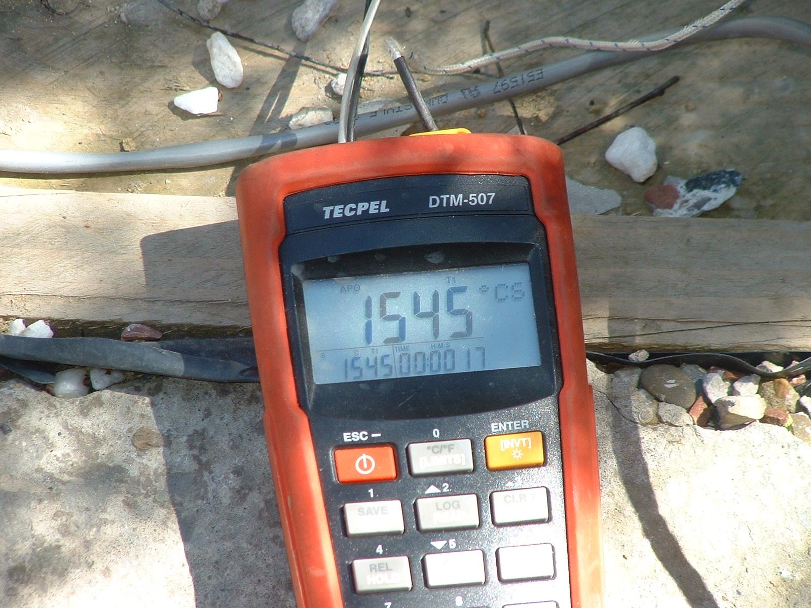
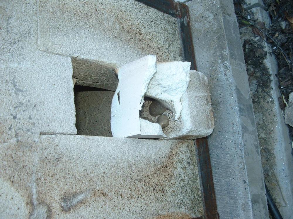
For any given manufacturer's products, the 2300 degF grade tends to be the better insulator, is lighter (less dense), and cheaper. For kilns, it is usually the better choice because the maximum kiln temperature tends to be less than "about" 2300 degF (less dense= lower thermal mass= faster heating. Better insulation= lower steady-state heat loss). For forges, 2600 degF-rated IFBs tend to be better and 2800 or even 3000 degF-rated IFBs "may" be better still, because the temperatures are higher. Even if the main forge temperature is below the rated temperature of the IFB, most burners tend to have parts of the flame that are hotter than others. IFBs tend to be a poor, or at least sub-optimal, choice for most forges likely to be built by anyone asking the question. IFBs are not usually good at tolerating steep temperature gradients and these are an inevitable consequence of the (very) rapid heat-up and (relatively) rapid cool-down most of us want from our forges. They tend to crack under these conditions due to differential thermal expansion and it does not take many cycles before they have cracked enough to crumble to something resembling coarse gravel. Industrial forges constructed from IFB are usually used in industrial production where the forge heats slowly, stays hot for a very long time, then cools slowly, preventing the steep temperature gradients. Despite their limitations, IFB forges are very good for some things. I have built IFB gas forges in the morning, assembling them dry into an angle-iron frame, and been using them by lunchtime. I could not realistically do this with a ceramic fibre blanket forge unless I did not seal the fibres in. I'm in the UK and our climate means that drying times are tediously long, but I don't even think a decent refractory coating could be properly applied, set/dried and fired in a day by someone working in a desert. One thing that I have found is that the expensive, branded IFBs tend to be tightly controlled to optimize certain characteristics. Using cheap import IFBs, which are denser, poorer insulators and are marked as 2300 degF grade, I have had no particular problem running to much higher temperatures than their rating would suggest is wise. I would not use them for a kiln, but they do pretty well for a forge The photos show the temperature measured in the forge (1545 degC is 2813 degF) and the effect this had on an off-cut of a KM23 IFB I had used to restrict the forge opening. The JM23s are the Italian-made equivalent of the US-made K23 IFBs and are from the same manufacturer. The JM23 melted into an impressively small puddle, given the volume of IFB lost. The rest of the forge was made from the cheapest, nastiest 23-grade IFBs I could get and survived pretty well (no melting at all). The cracking is visible in the photo. .

-
540W is 3/4 of a horsepower and is pretty weedy. The general rule-of-thumb is 1 HP (750W) per inch (25mm) of belt width. As you've used a bench grinder as the basis for the build, I'm guessing the drive wheel is mounted directly to the grinder shaft? If so, that's likely to be a source of cost if you change to a "real" motor. Most bench grinders have plain shafts of 1/2" or 12mm diameter, one or two of 5/8" and one or two of 3/4". Motors you are likely to encounter will have either 24mm shafts (90-frame motors) or 19mm shafts (80-frame motors). You will need to adapt what you have to whatever new motor you come up with. The detail design of your current system is important, as it goes a long way to determining how easy or difficult the change will be. Pics would be good. If the rest of the grinder is to a reasonably high standard (effectively permanent), I'd recommend going with a 90-frame 2-pole motor, which will most likely be 3HP. This is the biggest motor normally used for single-phase compressors and will run from a 13A UK domestic socket through a 13A fused plug. You'll need to check out your Consumer Unit(s) though. You may find the motor starting current trips the standard typeB breaker and that you need to change to a typeC. If you have old-school fusewire jobbies, you should be fine. The IEC motor standards mean that you can swap out the single-phase 90-frame motor for a 3-phase 90-frame motor and VFD if/when you want to upgrade to variable speed in the future.
-
Which jetting did you get? When running on Propane, I find the Butane jets actually give a slightly higher flame temperature than the Propane jets with the choke fully open (it's fully open in the first pic in post #7). You have sufficient control with the screw adjustment on the choke to go as much richer/cooler as you could ever realistically want to with either jetting, just by choking down the burner. The Butane jets are a bit smaller and give a "less-rich" mixture, though still somewhat rich/reducing. The factory jetting is based on industrial burner practice and almost certainly works on the assumption that there will be significant secondary air. Assumed/design working pressures are in inches water column, though I regularly use them up to 4 bar/60 PSI.
-
The Carbide grit ones are harder to find and the diamond ones are so cheap now that it's not worth looking. The biggest difficulty I see is finding one with enough depth to take out the lining in a single core. Most of the cheapies seem to be intended for tile and don't have much depth of cut. You may need to go for a "proper" dry diamond core drill, in which case the biggest problem you'll face is likely to be finding the right size. What refractory did you use?
-
1/ You need some sort of framework to hold the insulation in place. It might be suitable for that. 2/ There are plenty of suitable elements available. I'd probably use rod-type elements and mount them to the back of a plate to distribute the heat. 3/ Something like the linked controller, switching an SSR, would handle the power control. 4/ Use either an RTD (Pt100), or a thermocouple with a suitable temperature range, that will work with your chosen PID controller. For your unnumbered questions: How hard it will be depends a lot on what skills and experience you have at your disposal. You will need insulation and it will need to rated for the top end of your intended temperature range. I'd use a straight rod heater element rated for whatever power supply you have available. You should not need high power if you have reasonable insulation. It seems they either don't exist across the pond (which seems most unlikely) or are called something different Stateside: searching for "straight rod heater" on Amazon.co.uk brings up lots of hits, but on Amazon.com I get none that are useful. They'll bend when new, but seem to go brittle once they've been through a heat cycle or two so reusing old ones may be difficult. It's very easy if you know what you are doing. It's not too difficult to research it online, though you'll see quite a lot of complete drivel in with the pearls of wisdom. You need to be able to tell the difference. The best advice I can give on controllers is always the same: DOWNLOAD and READ the manual, from a readily-accessible, non-password-protected website. Only buy if, when you have read the manual at least a couple of times, it makes sense. Do not assume that it "must" be easy and will all make sense once you have it in front of you. The reason for the download from a readily-accessible website is so that you can ask for help on a forum with a link to the manual. Someone who understands process controllers has a pretty good chance of helping, even if they have never seen your controller. No link, no chance of help.If the manual is not online, buy a different controller.
-
Galvanized will be fine to use anywhere it's going to be cool enough to touch. As will black iron, though 1" may be rather small, depending on the size of the burner and the pressure available from the blower.
-
First thought is that those look like quite large gas jets. What size are the burners and what size are the holes in the jets? It doesn't look like there is much scope for fine-tuning by trimming the length of the jets, so getting the jet diameter right seems likely to be more critical than usual. I'd be inclined to tune a burner singly at first and then make the other three the same. I'm sure Frosty will be along shortly and he knows the T-burners better than anyone.
-
What pressure are you supplying? The first video seems to show the flame burning back up the burner tube (briefly). This suggests the pressure is way too low. Are you trying to use it with a low-pressure regulator (37 mbar for Propane over here, may be slightly different down there)? You'll need an adjustable high-pressure regulator that gives 0-2 bar (0-30 PSI) or a bit more. I tend to use 0-4 bar (0-60 PSI) regulators,
-
It doesn't sound like a cylinder problem, as there is no pressure reduction. I could be completely wrong, but I don't think the atmosphere in the garage will be the cause of the problem either. I would very strongly advise installing a Carbon Monoxide alarm or two if ventilation is restricted: death tends not to improve your bladesmithing. CO monitors are cheap, effective and will alert you to a potential problem while you are still upright. If the CO2 level in the atmosphere is rising, and the O2 level is dropping, by enough to significantly affect flamefront speed, I would expect the change caused to be a reduction in flamefront speed, which I would expect to reduce the problem, not increase or initiate it. If playtime is tight, I'd get a higher-pressure regulator before trying again. Most people seem to use at least a 0-30 PSI (about 200 kPa) regulator. I prefer 0-60 PSI/0-4 Bar (about 400 kPa) regulators. Is 130 kPa the maximum for the regulator, or "just" the maximum recommended pressure for the burner? If the latter, it would be worth speaking to the burner manufacturer for their thoughts on turning up the pressure. Going from 50 kPa to 130 kPa will increase the gas flow (and with it, the air flow) by the square root of the pressure change. The square root of (130 kPa/50 kPa) is about 1.61. That is not a huge working window. In many cases, a burner needs to be started at a lower pressure to avoid flame lift-off in the cold forge and it can be turned up once the forge temperature has reached about 800 degC (1472 degF) to get up to working temperature. I don't know whether this applies in your case, but if you need more than 50 kPa to reach working temperature, you will have even less headroom to turn it up if/when you run into burnback issues.
-
What were you doing with the choke in the video? A wide angle tripod-mounted view would probably be more useful for diagnosis than the fast-moving tight stuff, which is pretty disorientating. Am I reading things correctly? I think what I am seeing is as follows: Forge runs well, then it looks like it goes horribly rich and presumably the temperature drops if you let it? You close the choke and open it and it starts burning correctly for a short while before going horribly rich and repeating? If I've read it wrong, please ignore the following. If it seems something like it, what gas pressure are you running at? Can you try turning it up significantly? What I think is happening is as follows: From startup, everything is hunky-dory. The gas pressure is high enough that the mixture is moving towards the forge faster than the flamefront can burn through the mixture in the opposite direction and the flame stays in the forge. After about 45 minutes "something" changes and the forward mixture speed becomes less than the backward flamefront speed. The flame burns back into the burner tube. Because the mixture is now burning in the tube, it expands as it burns and increases the back-pressure, reducing the amount of air drawn in, sending the mixture excessively rich and reducing the forge temperature. You close the choke briefly, cutting off the air supply and causing the flame in the tube to go out. You open the choke, re-establishing mixture flow, which ignites as it reaches the hot forge and all is wonderful until the flame speed exceeds the mixture speed again. One possibility is that the mixture speed is dropping because the cylinder temperature is dropping enough to reduce the delivery pressure. If you have a pressure gauge, you can check whether the pressure remains constant from startup to the problem occurring and maybe get enough information to help with the diagnosis. Another possibility is that the forge temperature has risen to the point where the flame speed is faster than the mixture speed provided by the regulator. Flame speed in a Propane/Air mixture is dependent on temperature, pressure and the air:fuel ratio. If you have any headroom on your regulator setting, turning it up should raise the temperature at which it becomes a problem, hopefully out of the working range.
-
Ask wherever you get your Propane from. They should be able to either supply one themselves or put you in touch with someone who can.
-
It's always wise to put some sort of coating on, just to prevent airborne fibres when something unforeseen happens. Get some refractory cement (for <500 degF there's no point using anything expensive) and mix some of it with enough water to make a proper liquid out of which the sandy stuff will settle within seconds when you stop mixing. Pour off the liquid and slather it onto the blanket once it is in place. Some of the clay particles and binder will soak into the blanket quite deeply, though most will form a crust on the surface. What you will end up with is a hard crust over rigidized blanket that gets progressively less rigid with distance from the surface. Once dry (it's not quick to dry; this will likely take days), it will keep the fibres from escaping and resist gentle accidental knocks.
-
You need a pipeline supplier. BSS are national and have a place in Loanhead. They also have some brochures available online (possibly needing some faffing about to register) and a sort-of price list thing which is accessible online without registering, but is priced in industrial quantities. RS Components have a section of "malleable iron pipe fittings" that is worth a look online if you are completely new to pipe fittings and need to suss things out a bit before approaching a supplier. It is worth noting that pipe and fittings are sized on Nominal Bore and the sizes can a bit of a shock to those used to nut and bolt threads. If it is all new to you, look up BSP threads online. The BS pipe ODs are the same as for the US system, but the threadform is 55-degree Whitworth, rather than the 60-degree threadform used in the US. For a solid fuel system or blown gas burner, you can reasonably assume a US design will translate directly to UK pipe sizes and fittings. However, if you ever go on to build a Naturally Aspirated gas forge, the small differences can be enough to dramatically affect performance.