timgunn1962
-
Posts
393 -
Joined
-
Last visited
Content Type
Profiles
Forums
Articles
Gallery
Downloads
Events
Everything posted by timgunn1962
-
My forge keeps melting. Anyone know a good liner?
timgunn1962 replied to White Nomad's topic in Solid Fuel Forges
How much Lime are you adding? I was under the impression that Calcium Hydroxide melted at about 600 degC (Wikipedia tells me 580 degC, 1076 degF). Having experimented unsuccessfully with Waterglass (Sodium Silicate) as a rigidizer for blanket and as a binder for Zircopax, I have experienced the instant conversion from rigidizer to lubricant at around the melting point of the Waterglass ("about" 1100 degC, 2000 degF). The blanket just moves away from where the flame hits it and the Zircopax/Waterglass becomes a dribbly mess. It may well be that you are seeing the same effect from the lime? -
Old thread on what appears to be the same grinder.
-
2 bar, 30 PSI is usually fine. The square law for pressure vs flow through a jet in compressible fluids (gases) holds until the flow "chokes": the speed through the jet reaches the local speed of sound. This happens somewhere "around" 30 PSI for Propane. Going from 2 bar to 4 bar (30 PSI to 60 PSI) will therefore get you less than the 41% increase in gas flow that you'd expect to get if the flow didn't choke. There's no cost difference between a 0-2 bar and a 0-4 bar reg, and there's no noticeable difference in adjustability with the welding regs, so I tend to buy 4-bar for the "free" little extra at the top end. A 4-bar reg is nice to have, but doesn't give you much over a 2-bar in the real world. I think you'll find the 0-2-bar will be fine.
-
I'm pretty sure that's a 0.5 bar to 4 bar regulator; about 8 to 60 PSI. There are lots of them on ebay in the UK and they are complete dog-toffee IMO/E. I had a couple of them, tried one, threw both away. The 8 PSI minimum tends to make lighting the forge unnecessarily exciting and there's obviously no control at the lower end of what would normally be the working range. The best regulators I have found tend to be plugged (no gauge) 0-4 bar Propane regulators from welding suppliers. These usually have a scale showing the (approximate) pressure setting on the side of the body, where the skirt of the adjusting knob indicates the setting. It's usually not much less accurate than a cheap gauge and is considerably more rugged than any gauge. The regulator is designed for industrial use and fine adjustment by less-than-delicate individuals wearing welding gloves. About twice the price of the 0.5-4 bar cheapies on ebay UK and, I feel, considerably better value.
-
As Latticino says, this is (often?) caused by the speed of the flame-front moving through the mixture faster than the mixture is moving in the opposite direction. It usually starts when the forge gets fairly hot because the flame speed increases as the temperature rises. The flame will run back along the burner tube until it runs out of mixture (Propane will not burn unless it is mixed with air (or another Oxidising agent). The flame goes out. The gas keeps flowing, draws in air and mixes with it. The mixture reaches the hot forge and ignites. The process repeats. Every time the flame-front moves along the burner tube, it heats it a bit, making the flame speed even faster. If you can catch it quickly and turn up the pressure, you can often get the mixture speed faster than the flame speed and stop the problem. You have to be pretty quick to stay ahead of the burner tube heating up. You also need a big increase in pressure. The gas speed varies as the square root of the pressure, so doubling the pressure will only give a 41% increase in mixture speed. To double the mixture speed you need 4 times the pressure. Pussy-foot about giving it one or two extra PSI and you've got no chance.
-
To get from your hose to the BSP inlet (presumably 3/8" BSP), it is best to buy suitable fittings. Over here, NPT is the PITA and NPT-BSP adaptor fittings are available at decent pneumatic/hydraulic suppliers. In a pinch, I have been known to run a tap down the existing threads (BSP tap and NPT thread in my case) and fit a "local" fitting with plenty of anaerobic pipe seal, though not, as yet, with gas pipework. I think that the pipe nipple will probably screw in relatively easily, at least in the 3/4" size (1/2" and 3/4" have the same thread pitch in both NP and BSP). I always use an excessive amount of PTFE tape here anyway (BSP into BSP) to protect the female thread in the injector, and hand-tighten only. The PTFE tape is for padding only, not for sealing in this case, so there's no need to get too concerned about whether it's rated for gas. The clever bit about the Amal injector is the super-fine adjustment provided by the screwed choke and you really don't want to louse up the threads that provide this. I also dry-lube the thread further down to ensure it will adjust freely: Dry Molybdenum Disulfide, Dry PTFE, Graphite or some combination thereof. Grease tends to pick up dust and grit, making things worse, so I don't use it.
-
Twaddell units are a hydrometer density scale: the higher the number, the greater the density. Both are solutions of Sodium Silicate in water, as far as I can tell. Either will do the job: you'll (almost certainly) dilute it with water. I think I used the 140 Twaddell and it was seriously thick and viscous as it came. It's probably "about" twice as concentrated as the 75 Twaddell. Be careful with Sodium Silicate. It seems to melt somewhere around 1100 degC, 2000 degF. Used as a rigidizer for blanket, it is ok up to its melting point, but then it becomes a lubricant for the fibres allowing them to flow away from where the flame impinges on the blanket. It might work ok in a forge design that doesn't involve the flame impinging on the blanket. I gather a Bentonite/Zircopax (Zirconium Silicate) mixture has been successful for one or two folk. My limited experience of Bentonite in other fields causes me to feel it's not something I wish to experiment with. I would expect massive shrinkage on drying and I'd expect it to take a long time to dry (though I'm in the wet bit just North of Manchester, England and don't have a climate that's particularly conducive to drying: YMMV). I seem to recall posts on its use by someone who already had experience with pottery/ceramics and it's my guess that they'd already traversed that particular learning curve. I also have a vague recollection of them using Veegum/Bentone, rather than Bentonite, though I'll confess I have no real knowledge of the differences. I have used Zircopax/China Clay without much success (largely due to shrinkage on drying) and commercial Rigidizer/Zircopax, which was more successful: it dried without cracking, albeit slowly, and held up to welding temperature pretty well. I used a fairly thin mix of Zircopax in rigidizer, sloshed it on liberally so the rigidizer soaked into the blanket carrying some of the solids in to a depth of maybe 1/8"-1/4", but leaving most of the solids as a surface coating maybe 1/8" thick. I let it dry slowly for 3 or 4 weeks (in a Lancashire summer) before sticking the whole thing in a slow oven for a morning, turning it up in stages over an afternoon before removing it and carefully cleaning the oven before the wife came home in the evening. Commercial Rigidizer is usually a suspension of fumed Silica in water (there are also Alumina rigidizers). There are probably wetting agents and something to modify the pH (it felt like it might be mildly alkaline when I got it on my hands and washed them off, not unlike washing soda), but the main factor in determining how much Silica can be held in suspension seems to be the particle size. The commercial rigidizer will use the "best" particle size for creating a high-concentration suspension. Other uses of fumed silica include as a thickening agent for epoxy resins, and it seems reasonable to assume that these will use the best particle size for thickening resin. I tried using resin thickener to make rigidizer and the best I could manage was a Specific Gravity of 1.015 against a commercial rigidizer measured at 1.08. Clearly the Silica concentration was much lower and I surmise the particle size was different. I know others have used Silica suspension with Zircopax successfully. I think Tinkertim used a Silica investment binder (Morisol), rather than a proprietary rigidizer, and posted on here.
-
Heat treat oven build help
timgunn1962 replied to elijahjue's topic in Heat Treating, general discussion
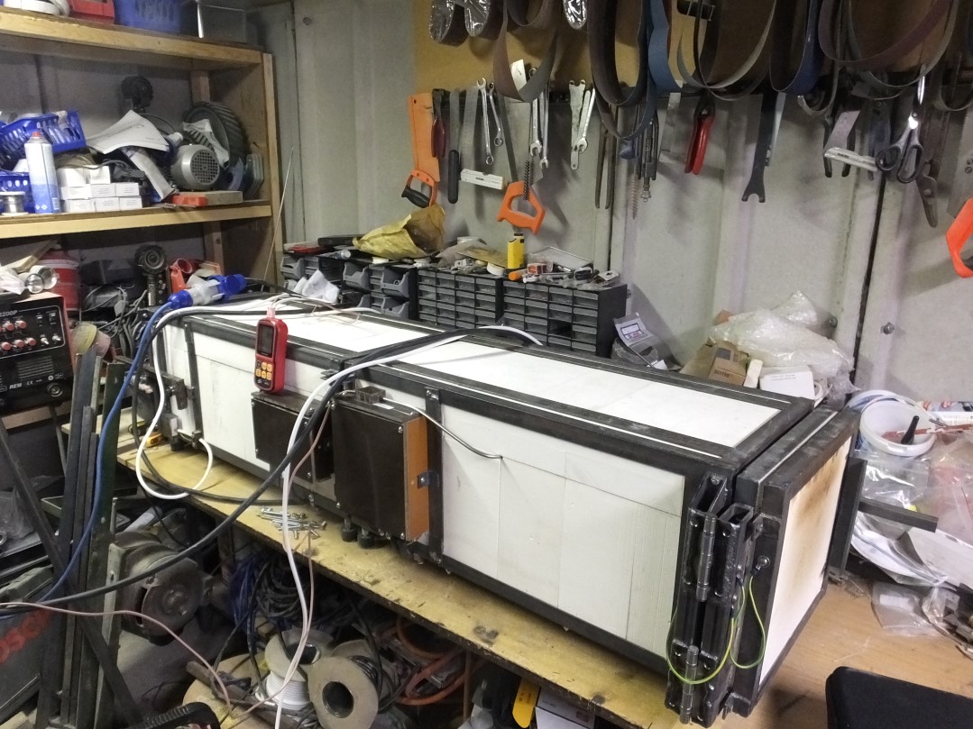
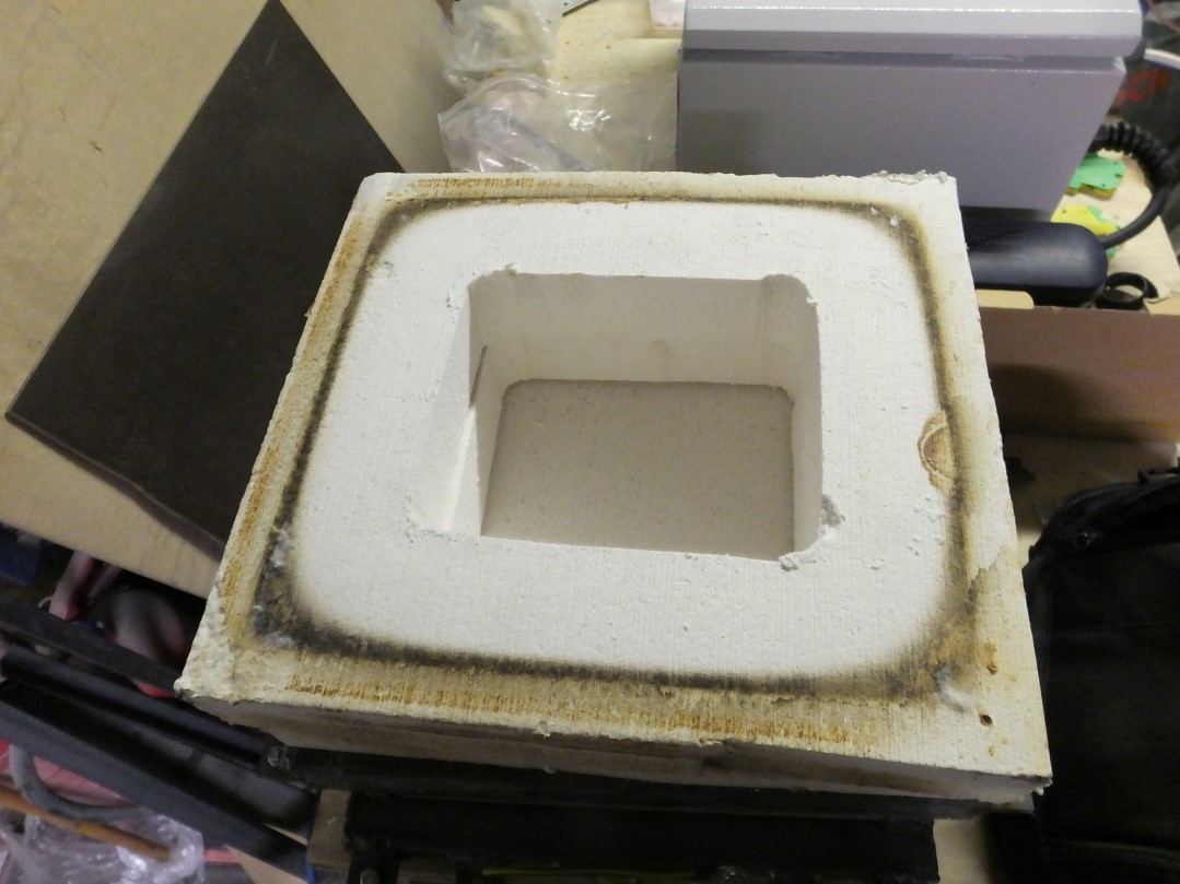
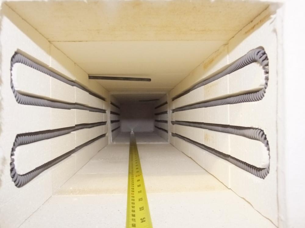
There are many variables and it's a really good idea to sit down and work out exactly what you need to do and what you have to do it with BEFORE you start building. Some of the stuff I can infer from the information provided: You have a 220V supply available. What current (amps) can it provide? I am in the UK, where the domestic outlets are 230V nominal and are rated for 13A, limiting me to 3 Kw in round figures (If I need to, I can go to 16A or 32A, but it means the user needs to have non-standard, industrial, sockets to feed the oven). I'm assuming the 1500-2000 degrees is Fahrenheit? The length certainly seems to suggest Carbon steel temperatures. That is much easier than needing higher temperatures for Stainless steels. Realistically, you don't really want to be getting too hung up about the stuff you cannot reasonably change, like the Voltage, the length of work you need to HT, etc. Watts per cubic foot or watts per square foot are not particularly useful unless you have all the information to hand and can deal with the math involved in calculating heat transfer rates. Understanding just enough to know when you are doing something different to established practice, and not deviating far from something you know works very well, is the path that most homebuilders of HT ovens take. Generally, it works pretty ok. You have obviously done quite a lot of the build already. My general impression is that you've almost certainly not loused it up beyond recovery. I've not used coils with diameters as large as yours, so don't have a feel for what will work: You may be completely golden. If you've not already done so, Google "Kanthal Handbook .pdf" and try to get your head around as much of it as you can. My most recent builds have been 27" long, 7" wide and 6" high internally, using 3 kW of elements, and have managed 1300 degC, 2372 degF, during testing, so I don't think you'll have any problem reaching Carbon Steel temperatures on your dimensions, unless the IFBs you have used are really lousy insulators (by IFB standards), or you have significantly less power available than I do. If you can let us know what power supply is available, we can work out the element power and resistance needed. Then we can calculate the surface loading. If you have any details on your IFBs that would be helpful too. I used 16AWG Kanthal A1 on my first few builds (I've built 8 or 9 to date) and some of the guys who use them professionally experienced element burnouts. I went to 1.6mm Kanthal A1 for the 3 most recent builds and, as far as I know, they have held up well for nearly 4 years. I have always tried to maximize the available groove length, in part because I'm middle-aged and grumpy and find it easier to get the staples in to retain the coils in the grooves if I stretch the elements to the longer end of the recommended range. I run 4 lengths of the sidewalls as a rule. My elements are about 3/8" OD and the grooves are cut with a 10mm bit in a router. The 7" width of my build has been largely dictated by the need to bridge the roof with a single brick. I build without mortar because I just don't have the knack of using the accursed stuff. I did build one quick-and-dirty 42" oven, 9" wide, that used a 3 kW element each side. That used Ceramic Fiber Board for the roof and solved the issue of bridging the 9" gap. The last 2 ovens I built were 6 brick-widths long (27") and the 1" blanket I use as a door gasket compresses down to 1/2" in use, adding another inch for 28" total internal length (because some bloody irritating bladesmith had suggested, in passing, that it might be a good idea to build two ovens that could be joined together to make one for long stuff, they got built with removable backs with blanket gaskets too. I anticipated some other bladesmith telling me that a mere 56" of combined length is too short, so built the doors and roof from Ceramic Fiber Board with the facility to add layers to the door and middle for more length)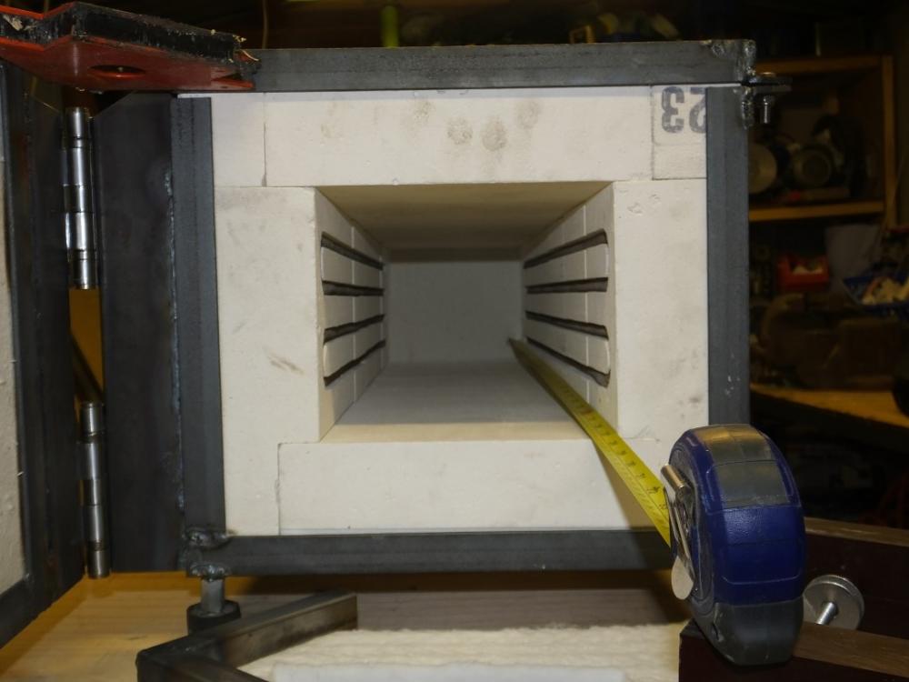


-
Are they Devil Forge burners? I would replace the worm-drive hose clips with 2-eared "O" clips. I am slightly (?) anal about it and use 2 of them at 90-degrees to each other. You squeeze up the ears on the O-clips with end-nips. The worm drive ones tend to drag the hose to a sort of D-shape and are more prone to leakage at the corners of the D in my experience (and yes I did use the recommended size). If you are using parallel-threaded fittings, use a good anaerobic pipe seal. As said above, you may need quite a lot more pressure to overcome burn-back up the burner tube. Moreso when you open up the chokes for higher flame temperatures.
-
If you are only heat-treating, you will not need a 3/4" burner. A 1/2" NA burner with fine adjustment of the airflow can easily heat a much bigger volume than that. I have built a few small HT forges using a burner based on a 1/2" Amal atmospheric injector. Intended as a cheap way to get good temperature control for a knifemaker on a budget. I used a 20" piece of 10" pipe, lined with 1" of blanket and with disks of 1" board for the ends, giving around 900 cu in. Everything got a wash of china clay in a solution of Sodium Silicate and water because it was cheap, immobilized the surface fibres and the forge was not going to get hot enough to melt the Sodium Silicate (it melts at about 1100 degC-ish, around 2000 degF). It will hold HT temperatures to within a couple of degrees for plenty long enough to soak O1 and similar steels once it is adjusted. The adjustment is by the knurled portion which is threaded into the injector body and has a pipe thread the same size as the burner tube. This gives superfine adjustment of the mixture and therefore the temperature. The burner has a flame retention cup made from a short (1") length of 3/4" pipe welded flush with the end of the 1/2" pipe and a 3" length of 1" pipe slid on and welded to it. Target temperature when the photo was taken was 800 degC (1472 degF). It was actually running at 801 degC (1474 degF). I was trying to make a smaller version of the Don Fogg 55-gallon drum HT forge. It wouldn't work for me at all until I turned it over, putting the burner port at the top and the work/exhaust port at the bottom.
.jpeg.72b28ba171b1a1c5f014786cb90afa11.jpeg)
.jpeg.2b66e2f01049add9ae361611da3f5d46.jpeg)
.jpeg.f8ab29c82b59f17fd4fc22809354ce88.jpeg)
.jpeg.135fa243514bc89f09712500867a4a69.jpeg)
.jpeg.1595f58893aabda56ee889d481615578.jpeg)
-
What is the smallest burner tube diameter and how many burners/ports? There is little point in jumping through hoops to get a blast gate in a 3” line if you are going to be reducing to a 1 1/2” burner with only a quarter of the area further down the line.
-
One factor in attainable thickness that I've noticed is the size of the grog/aggregate used. It's not really practical to cast a 1/4" thick wall if the lumps are over 1/2". Sieving it can overcome this, but may make it more crack-prone due to lack of reinforcement. These castables are/were formulated by competent folk who do/did it for a living. Generally speaking, I find it is best to read the manufacturers spec sheets and use a product suited to the task in hand, unless you are fortunate enough to have access to one of the technical guys who genuinely knows how far outside the published spec a product will go while still getting the job done AND who is properly familiar with the finer details of the process.
-
I can't think where I've seen it, but I have a feeling that Devil Forge may use a MegaPascal-marked gauge, though I would imagine this may vary by destination. The cylinder fittings vary by country and, IME, regulators usually come with gauges marked in the customary units for the country/region they fit. .1 MPa is 1 bar or 15 PSI.
-
The highest I have measured in a Propane forge was 1556 degC (2833 degF) and still rising. I didn't want to risk the $400+ typeS thermocouple, so didn't wait to see what it would top out at. I measured a forge at a hammerin a few years ago. It was being used for pattern-welding blade steels and was right around 1300 degC (2372 degF). As I understand things, it had been adjusted to give a temperature suitable for "anyone" to weld in and I regard 1300 degC as a good target temperature for a (bladesmiths) welding forge. The more experienced pattern welders tend to use a lower temperature (probably around 1200 degC) because it gives crisper contrast between the different-coloured layers. One caveat is that High-Carbon blade steels tend to need lower temperatures than lower-Carbon steels or Wrought Iron. However, if you are getting 1400 degC and have Dragons Breath (The DB is a sign of a reducing atmosphere: a secondary burn that takes place when hot, partially-burned gases reach fresh air containing enough Oxygen to complete the burn), you should be ok for welding pretty much anything.
-
I do not fit ball valves on my burners. My rationale is as follows: In normal operation, all adjustment and on/off control is done from the regulator, which is at the cylinder. It is where I habitually go to adjust or stop the gas. It is at the upstream end of the relatively fragile hose and it is reasonably well away from the hot bits. If the midden hits the windmill, I do not want options. I do not want to have to spend any time at all, however brief, assessing the situation and deciding whether to use the "safety shutoff valve" that may have been provided in the hot area where things are going wrong, or the cylinder valve in the relatively safe location. I will go to where I habitually go and do what I habitually do to shut things down and that is at the cylinder. It is the safer place to be. I will close the cylinder valve. Admittedly it will take a fraction of a second longer than closing a ball valve, but I will have saved that fraction of a second, and more, by not having to make a choice earlier. Others may feel differently. As a general rule, I'd rather not share a shop with those who do.
-
You are right and I am wrong. Thanks for correcting me.
-
The pressure in a Naturally Aspirated burner is needed to impart speed to the gas issuing from the jet. There is some quite complex, and not particularly intuitive, Physics going on, but basically there is a conservation of momentum thing happening which draws in air and mixes it with the gas. In a blown burner, the air is forced in, rather than being drawn in by the fast-moving gas stream, so there is no need to have high pressure and a high-speed gas stream. A bigger jet will give a lower speed for a given gas flow and the lower speed is obtained with a lower pressure. High speeds tend to be associated with laminar flow, while low speeds tend to be associated with turbulent flow. Turbulence is needed to mix the gas and air effectively, so lower gas speeds are preferable where high speed is not needed to get the air in the first place. Flow through a jet varies as the square root of the pressure: half the flow needs a quarter of the pressure. Double the flow needs 4 times the pressure. If you are going to use a “jet”, it and regulate the gas flow on pressure, the “jet” needs to be sized to give a useful range of flows across the pressure range you can set with your regulator. Finding an appropriate jet size for a NA burner is the difficult part. Not needing to do it for a blown burner is probably the main reason blown burners are usually considered easier to build. If you use a needle valve (which can be thought of as an adjustable-area “jet”) to control gas flow, you don’t need to worry about regulator pressure overmuch.
-
1mm gas jet on a blown burner seems very small. Are you getting any Dragons Breath? If not, You are probably running too lean and would benefit from a bigger gas “jet”. A small jet and high pressure are needed in NA burners because the gas velocity needs to be high to entrain air. Blown burners have the blower for the air and gas velocity is not needed.
-
emissivity of forged steel measuring temperature
timgunn1962 replied to bbaley's topic in Metallurgy
I had an IR thermometer, good to 1600 degC. Pretty close to useless for most smiths. It ended up with a guy who makes some nice kitchen knives. He uses it to check for consistent temperatures when taking billets from the forge as they come out. Once he’s got the first one or two working right, he doesn’t care what temperature value he is reading, just that the reading is the same each time. When the steel is in the forge, it scales to some extent. When it comes out into the air, it scales some more. When it gets hit, the scale gets knocked off and immediately starts reforming. The emissivity changes with every process and every second that passes. There is no one value that will give accurate temperature readings. -
I did a bit of playing with jet sizes and found the Butane jetting to work very well on Propane forges. I think the factory jetting is intended for “normal” heating applications which use both primary and secondary air. For Propane forges, there is usually no secondary air so the Propane jetting runs pretty rich and not quite hot enough for welding. The Butane jetting is smaller, so runs less rich and a bit hotter when burning Propane: certainly hot enough for welding bladesmithing steels, though I don’t know whether it will manage WI welding temperature. It’s still rich enough to limit scaling in the forge, so there’s some scope for reducing the jet size further to get even higher temperatures if needed. The Amal jets are available in closely-spaced increments and the sizing is pretty intuitive.
-
Try increasing the size of the hoses. If you can double the diameter of the long section, the area will increase by a factor of 4 and the pressure loss will go down dramatically (the physics gets complicated, but a first approximation is that the pressure loss varies as the square of the velocity, so you'd get something of the order of one sixteenth of the pressure loss along the same length at the same flowrate). Shorten the hose and the pressure loss will vary with the length (as a first approximation). Ten feet of 1 1/2" hose will give "about" one fortieth of the pressure loss of your twenty-five feet of 3/4" hose. If you go for 1 1/2" hose upstream of the tee, get the tee as close as possible to the burners and use the 3/4" hose (that you already have) between the tee and the burners, things will probably get a lot more manageable.
-
It sounds to me like you probably don't understand the physics well enough to be asking the right questions. The lines between blowers and pumps can be blurry at best.It's certainly not as simple as changing from one to the other at a defined pressure. "200-300 CFM" is a very wide range when considering the pressures needed to drive flow through a tube. I'd suggest an online search to find the catalog for "Rotron Regenerative Blowers" and read the technical stuff near the back. It'll either give you some answers or will give you a better idea of the appropriate questions. There is a "friction loss per foot of tubing" chart that should prove particularly instructive.
-
Can you buy jets for the burner separately? If it needs secondary air as it stands, with the choke fully open, to get the maximum temperature that you need, fitting a smaller gas jet will increase the primary air:fuel ratio and reduce or eliminate the secondary air requirement. I would find out what jets are available, if any, and how fast you can get them, before butchering the burner mountings. That way you can see what you get and decide whether to try different jets or cut-and-shut if it does not do what you want.
-
On the 3/4”, I think the threads in the body are 3/8” BSPT, which will be “about” the 15mm-ish you mention. Personally, I would use a 3/8”BSP hosetail with the barbed end sized to suit the hose. I use O-clips to secure the hose. If your configuration has the burner at top-centre, pointing downwards, there is likely to be some chimney effect and the heat transfer up the burner when it is shut down may make using hose unwise. Rigid metal tubing may be better.
-
Stuff happens. I think we all knew what you meant. Occasionally making a mistake is normal: it certainly doesn't mean you should stop thinking. I only pointed it out because it's the internet and someone encountering this thread at some point in the future might otherwise pursue a path of extreme frustration.