timgunn1962
-
Posts
393 -
Joined
-
Last visited
Content Type
Profiles
Forums
Articles
Gallery
Downloads
Events
Everything posted by timgunn1962
-
Heat treatment oven from an air tank
timgunn1962 replied to Ted Ewert's topic in Heat Treating, general discussion
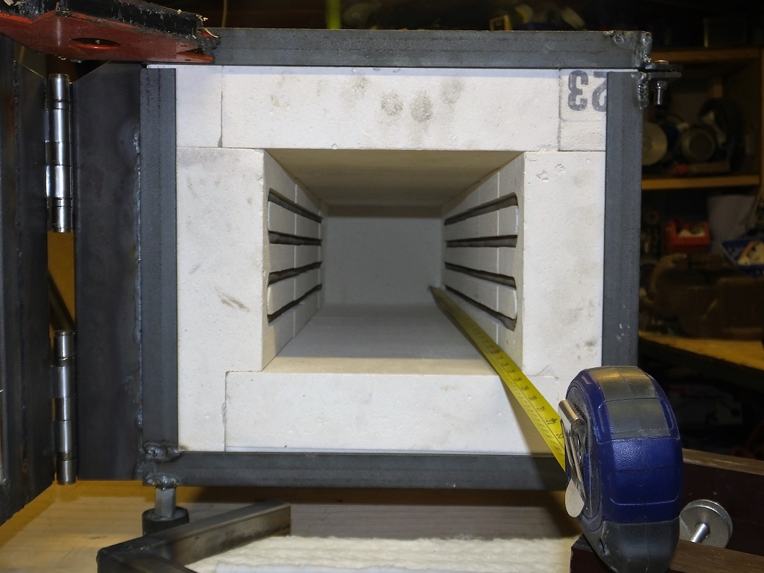
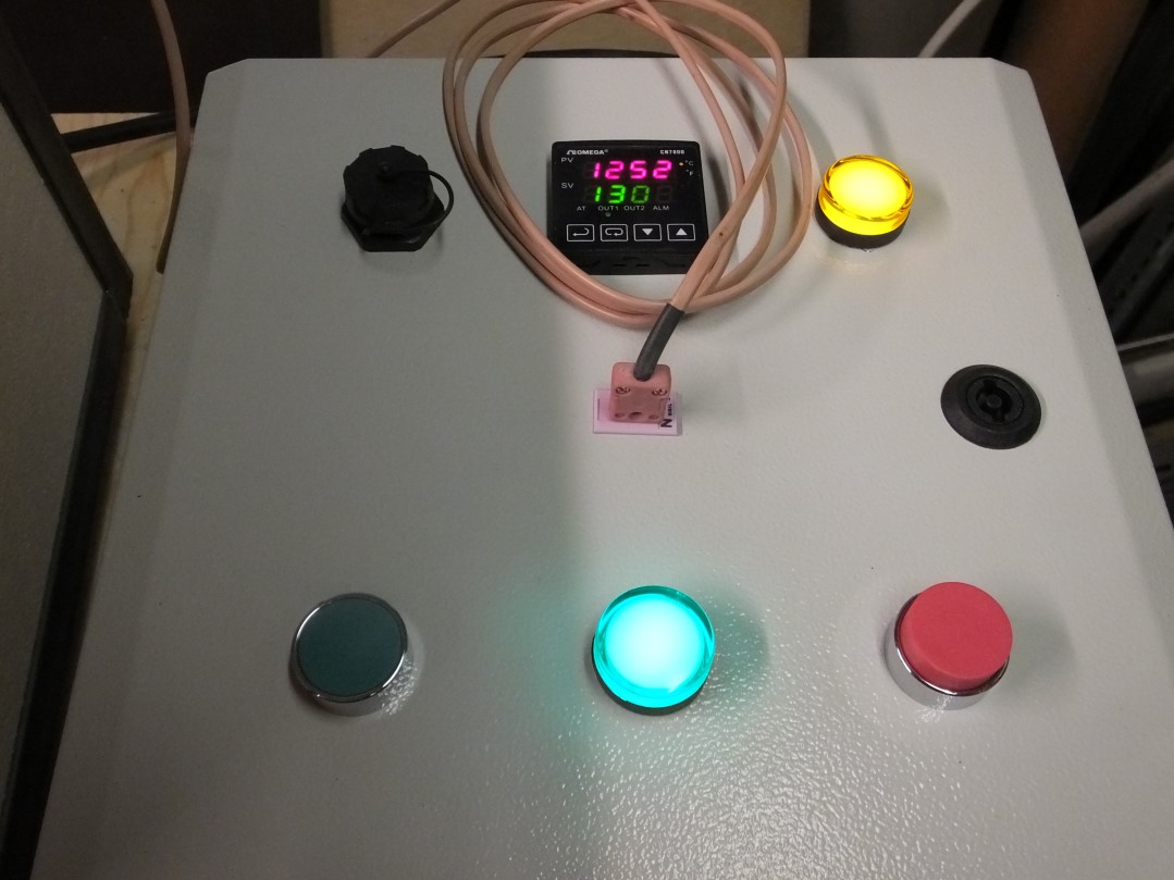
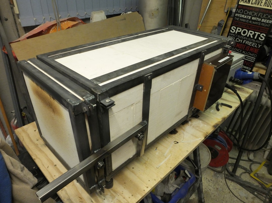
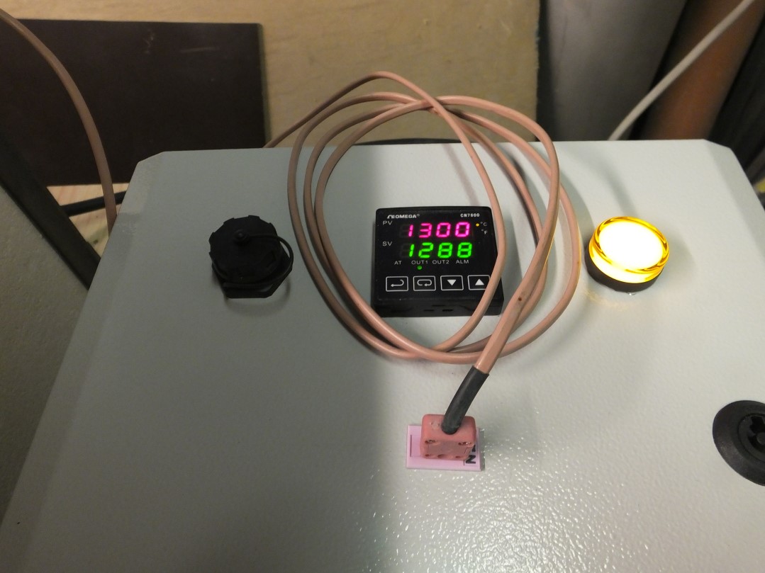
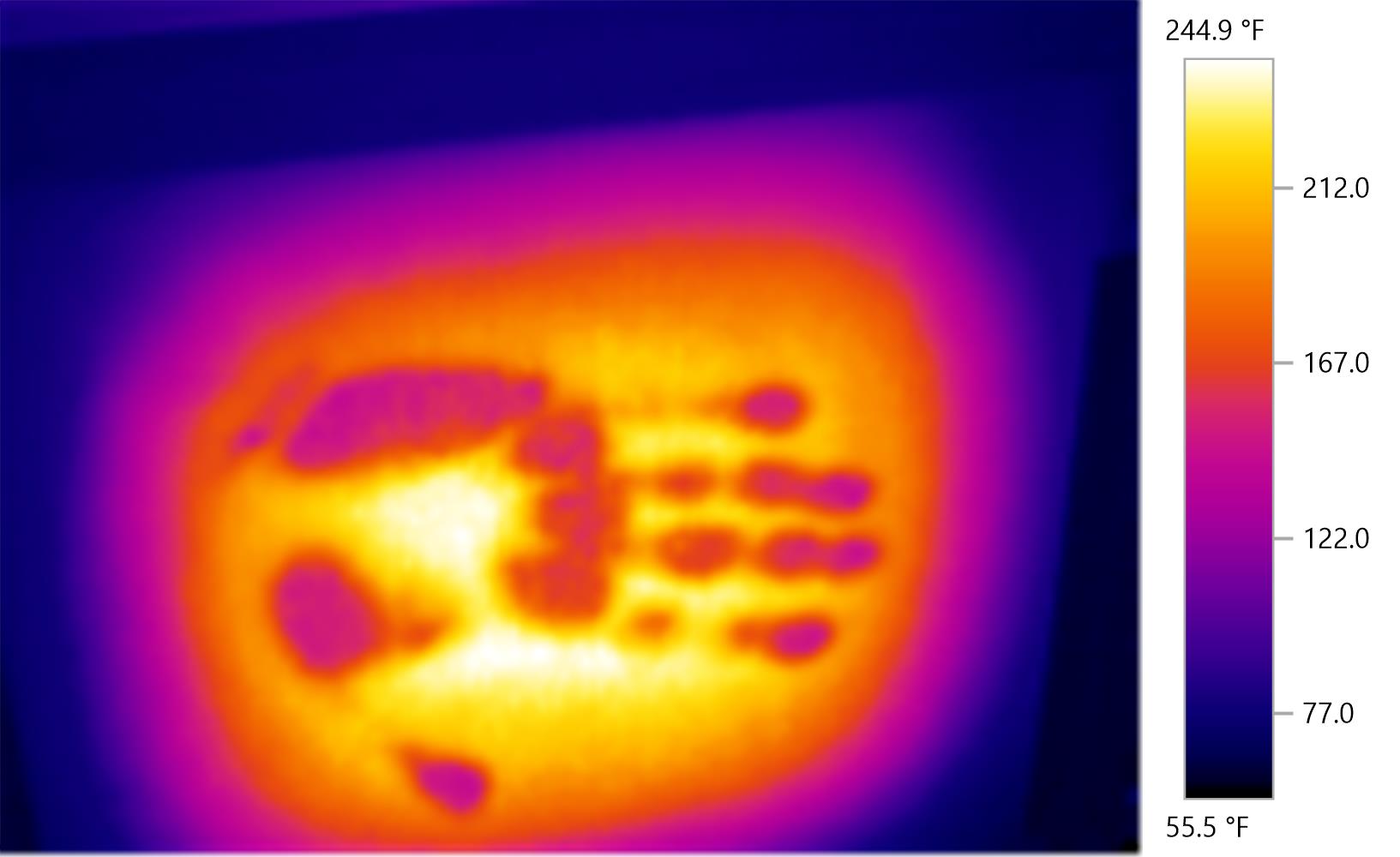
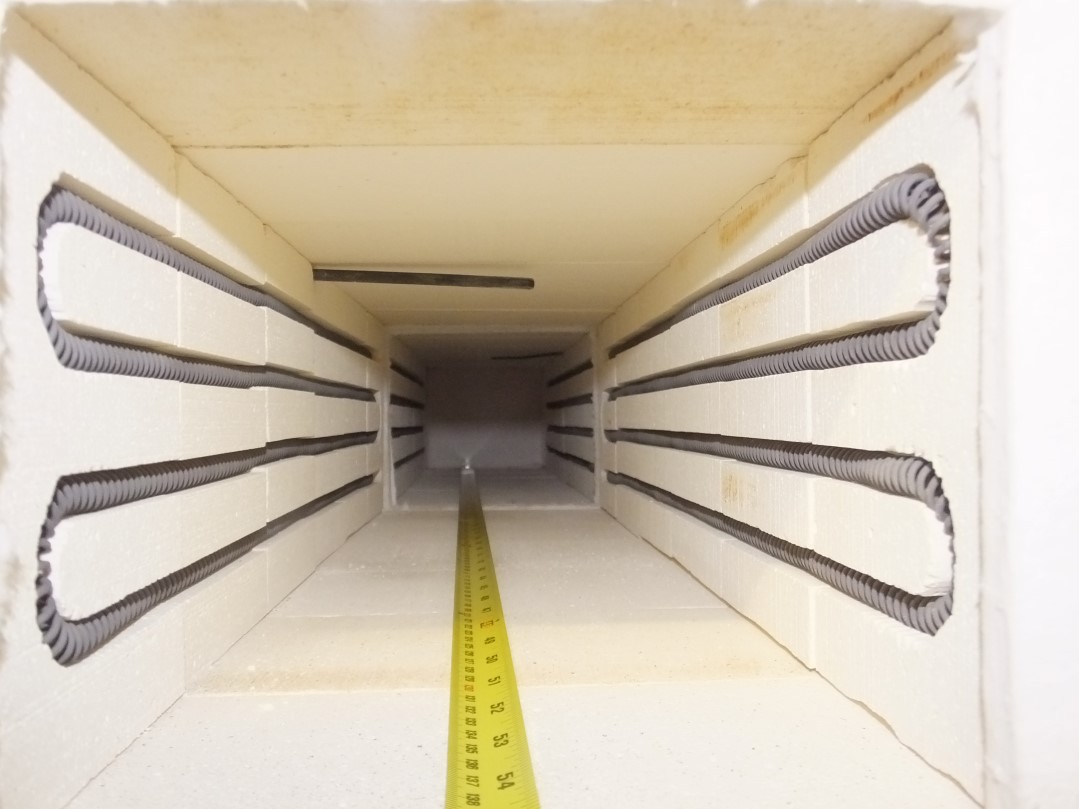
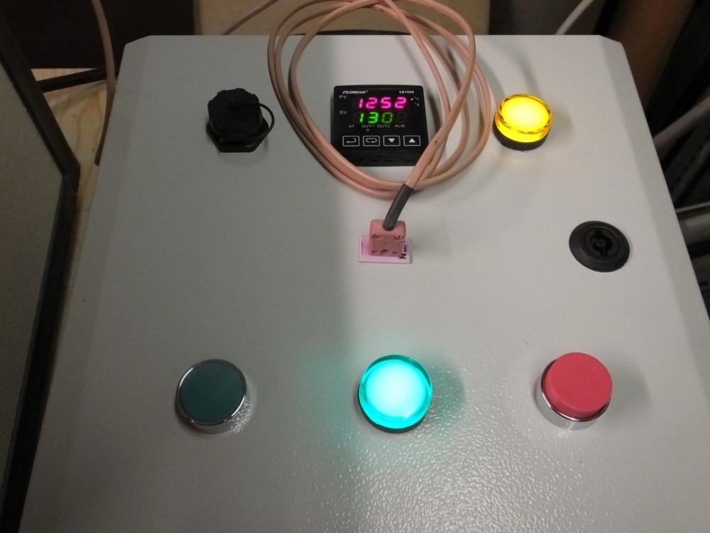
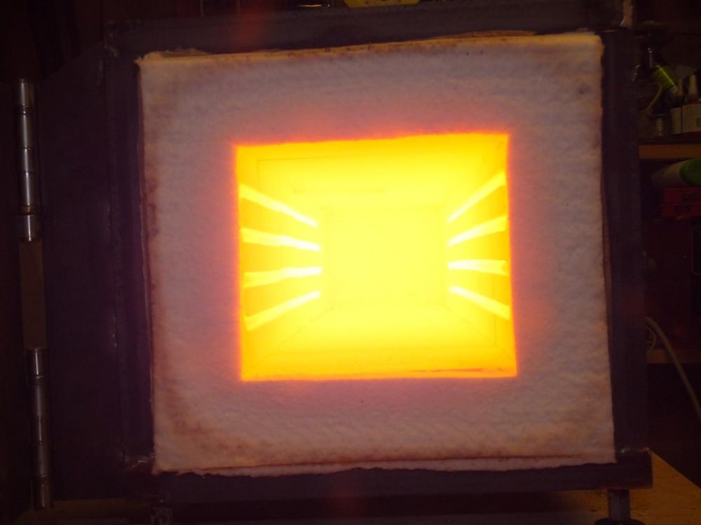
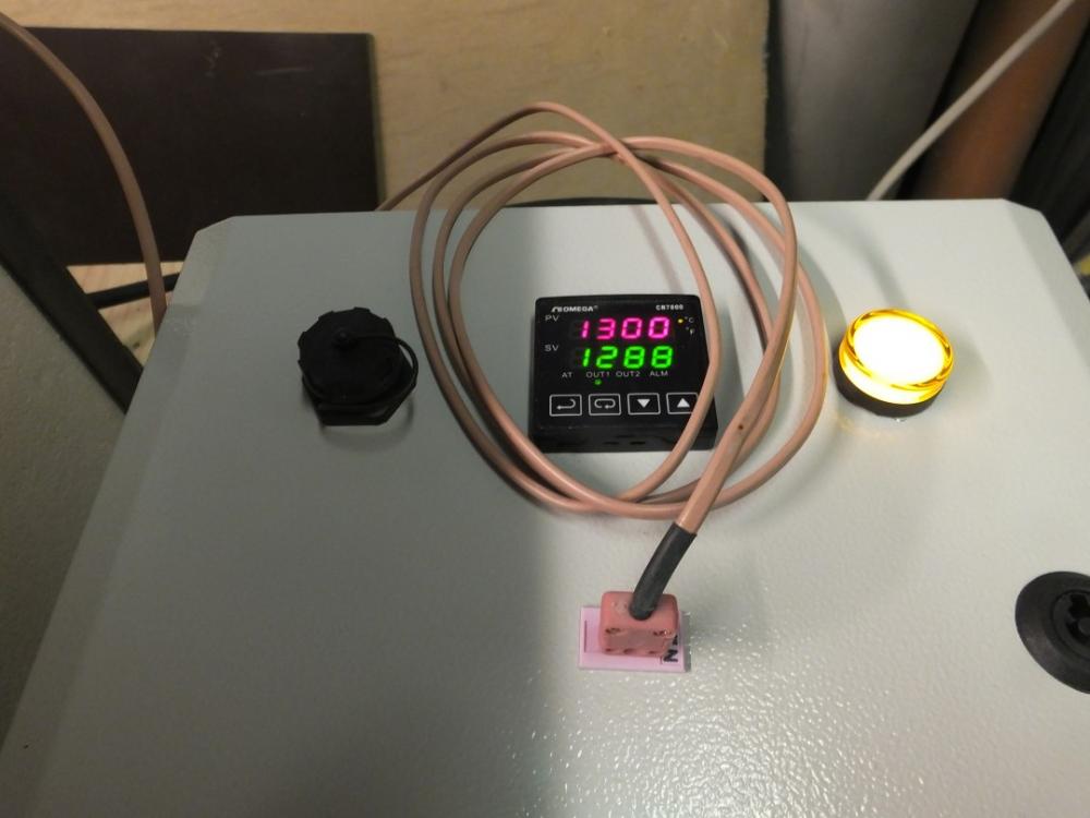
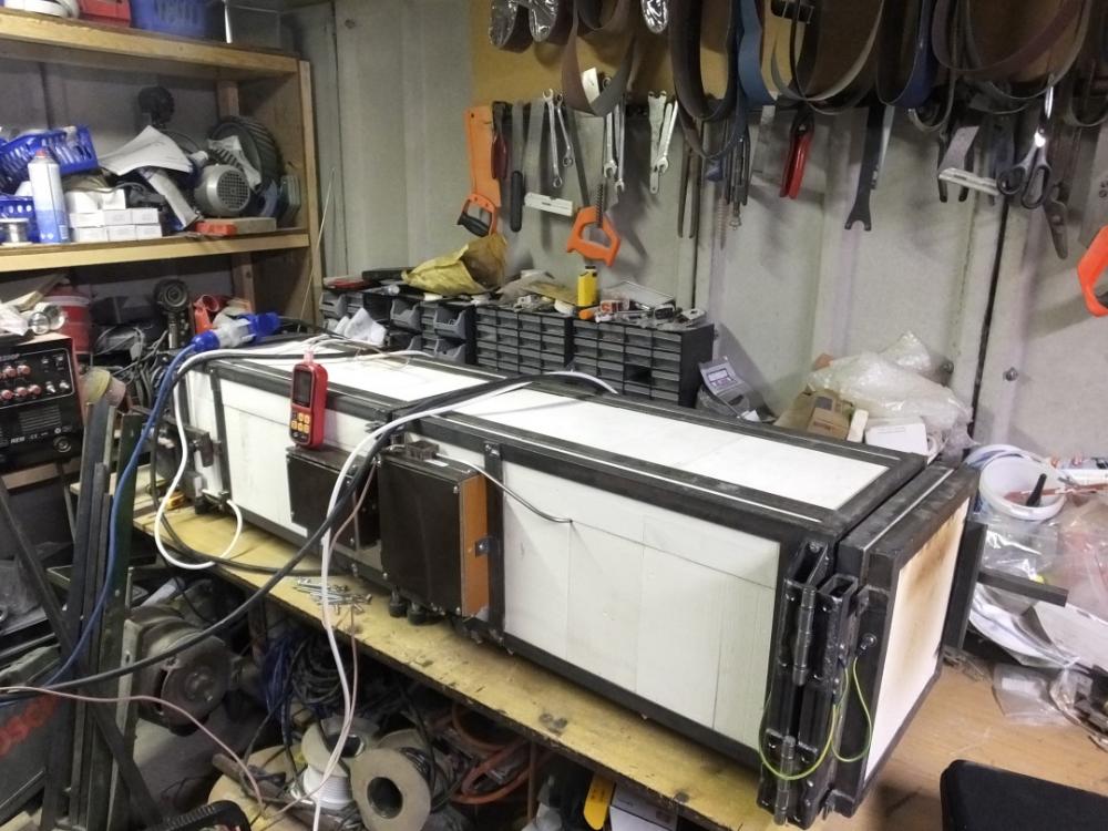
I think the tank might be more trouble than it's worth. Square is much easier when using IFBs. When I built my first HT oven, I used a frame welded up from 1" x 1" x 1/8" angle and 1" x 1/8" flat. I expected to need to skin it in sheetmetal. Not knowing what temperature it would reach, I decided to run it and see, as the temperature would dictate the most cost-effective material for the skin (Plastic-coated steel, Galvanized steel, Aluminium sheet, Stainless Steel sheet, in increasing order of temperature/cost). In the event, I found it all worked fine without skinning and the IFB gave a much lower heat transfer to human skin when touched than any of the prospective sheet-metal skin materials. The result was that I seemed to have found a very safe, very cost-effective, solution wholly by accident and have used it ever since. Whilst there is nothing technically difficult about building an HT oven, there is a lot to think about and pretty much every design decision impacts something else. Element life is largely dependent on element diameter: thicker wire lasts longer, all else being equal. Thicker wire has a lower resistance, so more length is needed for the same power at a given Voltage. This tends to mean that thicker wire needs a bigger oven. To reduce the power output for a given wire diameter and Voltage, the length needs to increase. For a 230V, 3000W, oven, about 18" is the shortest chamber length I have been able to comfortably build using 16AWG Kanthal A1. I built 4 ovens with 16AWG elements and they went to knifemakers. There were 2 element failures, which I felt could be at least partly attributed to the element wire diameter being small. I built the next using 1.6mm/14AWG elements and increased the length to 22 1/2" to give a longer groove to put them in. I tested the oven and found it would easily achieve 1300 degC/2372 degF, the upper range limit of the type N thermocouple I use (type N has better high-temperature stability than type K and is MUCH cheaper than types R or S). The next 2 ovens I built used the same 16AWG elements and were each 27" long. Again, they would easily reach 1300 degC. They were designed/built to join together to make one long oven for swords. The thermal image was taken just after pressing my bare hand hard against the door (2" Ceramic Fiber board) for 10 seconds. I'd previously used IFB for the door and was checking to see whether the CF board also seemed safe. Joined together for long stuff: Apologies: this may have become something of a thread hijack and that was not my intention. If you are looking to keep it small, I would recommend going with 110V. You already have a ramp/soak controller, which is very helpful for controlling overshoot when you have powerful elements relative to the thermal mass of the oven. It does mean that you need to use the ramp function and that you need to set the ramps having mapped the heating (and cooling?) curves for the oven, since most of the industrial ramp/soak controllers I have encountered do not have the guaranteed soak function that is built in to many of the kiln controllers. Do you have a link to the controller manual?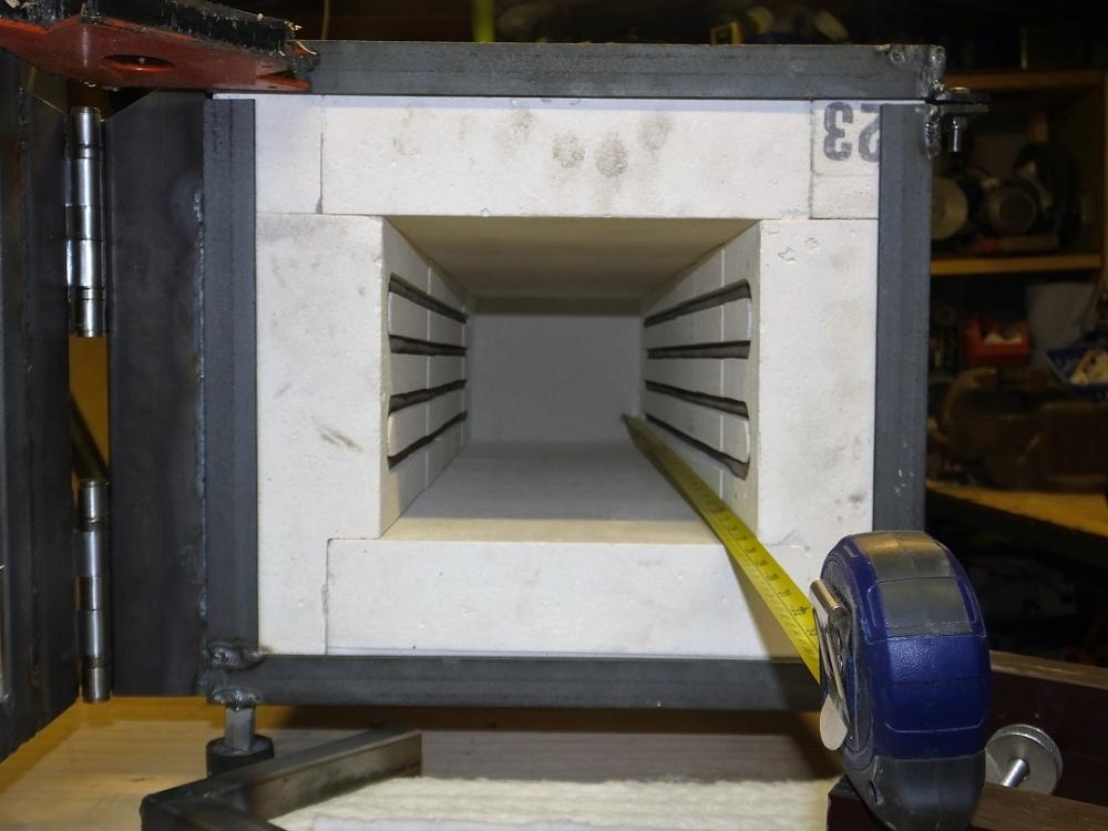


-
Motor question- VFD or single phase
timgunn1962 replied to Dan P.'s topic in Power Hammers, Treadle Hammers, Olivers
Dan, can you get a pic of the VFD plate or let us know the make/model? I'd say it looks like a current limitation from the VFD. The first thing I'd check is that the VFD is not set up for a quadratic torque application (pump/fan) as it's just a pushing buttons job. Next would be to check the motor wiring in the connection box (that it's not star/wye-connected instead of Delta, assuming you are on 230V 3-phase); a screwdriver job. After that, it's a case of checking the settings in the VFD and maybe breaking out a multimeter. -
I have no experience with them at all. They do look very shiny. There is a theoretical advantage to having a shiny surface on the outside of the forge: it will reduce radiative heat loss. The effect is small, infinitesimally so compared to other simple measures that can be taken. If the remainder of the forge showed any indication of having been designed to minimize heat loss, I'd actually be quite impressed by the shininess. The burners may be extremely good. The choke looks to be screw-adjustable and I would expect the mixture control to be very good indeed (assuming it has been jetted correctly). If you have an intended use that needs a high level of precision, this is likely to A Good Thing. Burners with screw-adjusted chokes can usually provide the stable (low) temperatures needed for Heat-Treating knives in steels that need a good soak at temperature, O1 and 52100 for example, if that is your interest. Where precision is less of a concern, a sliding choke can provide adequate adjustability: fine if your requirements are plus/minus perhaps 30 degF or so. There are lots of sliding-choke burner designs out there. I tend to use burners based on Amal Atmospheric Injectors, a range of screw-adjustable-choke commercial Venturi mixers that seem to have made converts of almost all the bladesmiths I know who have used them, and a blacksmith or two. These are UK-manufactured and threaded BSP, so are probably not so easy to use in the States, where NP threads are the norm. The Devil Forge DF-series burners from Lithuania are less shiny and cheaper than the Fucina burners, but have a similar choke arrangement. I have found them to be excellent. I have used them successfully in homebuilt forges, though I have not tried a Devil-Forge manufactured forge. A few things leap out at me from the Fucina site. First is that they offer a 0.5-3 bar (7-43.5 PSI regulator). My experience with such regulators is that turndown is not as good as I'd like at around 2.5:1 (gas flow varies as the square root of the pressure. 43.5/7 PSI is a 6.2:1 pressure range. The square root of 6.2 is 2.5). This means that you can only turn down to 40% of maximum. Starting at 40% always strikes me as unnecessarily exciting. To be fair, the ball valve downstream of the regulator probably allows a controlled lighting technique but it does put the operator at the forge, rather than at the regulator a few feet away, when it lights. The claimed burner pressure range is 1-45 PSI and the recommended range is 4-10 PSI. It seems strange that the 7PSI minimum regulator provided can only supply pressure over half the recommended range. A cylinder pressure regulator is useful for showing cylinder contents when using compressed gases (Argon, Oxygen, Nitrogen, etc). Propane liquifies, so the cylinder pressure gauge will normally show the Vapor pressure above the liquid, right up to the moment when the last of the liquid is gone and the cylinder is effectively empty. While there is still liquid in the cylinder, the vapor pressure is dependent solely on the cylinder temperature. A 2-gauge regulator therefore has one gauge that is effectively just for show. 304 stainless steel has never seemed a good choice for the hot end of a burner to me. It tends to Oxidize when it gets hot and the Oxide layer spalls off as it cools, so it will lose an Oxide layer each time it cools from hot. This happens with all the (Austenitic) stainless steels, but 304 and 316 have about the lowest cycling temperatures. These will lose the Oxide layer with cycling through about 850 degC (1562 degF), while 310 does not tend to lose its Oxide layer until it is cycled through about 1100 degC (2012 degF). I tend to use 310 for flame retention cups because of this. It may be that I'm a cynical old codger, but I find I get very nervous when presented with a tool which has obviously been designed/built with appearance prioritized over performance. The Fucina Forge website does not give me the warm fuzzy feeling I'd like it to. Gratuitous use of type 304 stainless steel, appearance infinitely more important than performance: does anyone else remember DeLorean cars?
-
Several designs call for a "flare", usually with a 1-in-12 taper. This is the empirically-determined "optimum" taper for the downstream section of a classic Venturi. In most forges, neither a flare nor a flame retention cup is usually necessary (though they can be advantageous in some cases). At the inlet end of the (Naturally Aspirated) burner, fast moving gas exits the jet and a low-pressure zone is created around the jet which draws in the surrounding air. If you run a NA burner in open air, fast-moving gas/air mixture exits the burner and a low-pressure zone is created around the burner exit which draws in the surrounding air. As the burner is turned up, the flame tends to detach and go out. If you apply a flame from something else to the edge of the burner nozzle, the flame will usually light and remain attached for as long as the pilot flame is present. If you move the same burner into a forge, the mixture still emerges from the burner and still generates a low-pressure zone, but in the closed forge there is no air to be drawn in, but there is a lot of flame. This is drawn in towards the burner nozzle and keeps the flame attached. As I understand things, a flame retention cup works much like a forge-in-miniature, causing a donut-like ring of flame to form on the "shelf" where the diameter steps up, keeping the flame attached. I make my flame retention cups with a short length of pipe twice the size of the burner tube and odd bits of intermediate-sized pipe to fill the gap between them: loosely based on the design shown in http://amalcarb.co.uk/downloadfiles/amal/amal_gas_injectors.pdf. I have found these retention cups work well when a burner needs to be run outside a forge.
-
The Hybrid Burner web page gives the .045" tip as the one for "only a bit rich", so it should give forging-to-welding temperatures easily. It "should" give the hottest (and least reducing) flame when the choke is fully open. The choke sleeve in the bottom photo is about half-way open/closed. What happens when you adjust it? When you look into the forge (check out the safety stuff elsewhere. There are risks), is there a cooler spot apparent (by color) under the flame entry? What sheath material do you have on the thermocouple in the middle photo? If it will allow you to measure forging temperatures, it's a good way to get objective data. The color coding on the cable suggests it's a type K which will read to 2500 degF, but the maximum temperature it will tolerate without damage is likely to be lower and is dependent on the sheath material. You certainly have a rich mixture (less air than stoichiometric), judging by the Dragons Breath. However, I'm not good enough to tell from the photos whether you have a low gas flow and a lot of DB for the amount of gas being burned (indicating a strongly reducing forge atmosphere), or a high gas flow and relatively little DB for the gas being burned (indicating a less-reducing forge atmosphere). For the guys who are better at diagnosing this stuff than me, some more details would probably be helpful: What is the forge built from? How big is the opening? Is there just the one opening, or one at the back too? What gas pressure are you running? What are you heating and how hot are you getting it? Does/can the forge get the work hotter than you need?
-
Naturally Aspirated Ribbon Burner. Photo heavy.
timgunn1962 replied to Frosty's topic in Ribbon Burners
Sorry, I'd missed the blown thing. I'd lose the .035 mig tip first. The mig tip is appropriate for a NA burner, less so for a blown burner. The gas velocity changes with the square root of the pressure across the jet (until the flow "chokes" when the velocity reaches the speed of sound: this happens somewhere around 30 PSI in "our" application). NA burners need the gas velocity to entrain air. Blown burners do not. You do need to be able to control the gas flow adequately and this can be done with a gas jet and variable pressure, or a needle valve, which is essentially a variable-area orifice, at a fixed pressure. On Ron Reil's site, there is a link to an orifice flow calculator. An .035" mig tip will probably have a hole diameter of around .042". You can plug in some pressures and see the flows. Note that the flow changes as the square root of the pressure. To double the gas flow, you need 4 times the pressure. To halve the gas flow, you need one-quarter the pressure. I'd use the calculator to determine a jet size that, at 30 PSI, gives about the maximum BTU value you think you might need, based on the forge volume and whichever BTU/cu.in. value you feel comfortable using. Drill out the mig tip to that size (or the next available drill size up). The mig tips make nice gas jets largely because the hole has a lead-in taper (to help center the wire) that just happens to have really good gas flow characteristics. The default Discharge Coefficient of 0.75 in the BTU calculator should be about right for a drilled-out mig tip. This should give adequate control of the gas feed with the regulator adjustment. Alternatively, just take out the mig tip altogether and fit a needle valve. -
Which jet are you using in it?
-
Naturally Aspirated Ribbon Burner. Photo heavy.
timgunn1962 replied to Frosty's topic in Ribbon Burners
The Gasoline 14.7:1 ratio is by mass: Gasoline is usually introduced into the airstream as a liquid. For Propane, the stoichiometric ratio is 15.67 by mass or 23.9 by volume. I've not really found that knowing the numbers makes much difference in reality. There are so many variables in a NA burner design that it has always been a case of taking a fairly wild guess and then making the adjustments indicated by the way the flame/forge behaves. I usually try to start with a jet that I am pretty sure is too small, then open it out in stages until it does what I want it to do. My guesses have not been too far off as a rule and the burners have tended to run too hot and too lean, but they have burned. I stop opening the gas jet up when I have reached a size which gives just a bit hotter than I will ever want, but with a rich burn (reducing forge atmosphere). -
I've not used Kast-O-Lite yet, but have used the domestic oven for drying out small single-burner forges. Reasonable safety precautions need to be taken: I do it when my other half is out for the day. Assuming you have not introduced anything nasty with the shell (paint, oil, etc, depending on the source of the shell) or with your rigidizer (surfactants?), you "should" have no problems at all. As far as I can tell, the KOL does not need to be "cured" with heat, as it undergoes its chemical changes at room temperature. The slow heating schedule is simply to dry it out. I weigh the forge once I've left it for as long as I can to air dry (usually weeks here in Lancashire. Austin should be much quicker). I weigh it every hour or 2 during the oven drying. When it stops getting lighter, I give it another hour with the oven on full and call it dry.
-
It is generally intended as a spring steel, so most of the real-world applications will have a spring temper and the data sheets reflect this. For blades, it will usually need a lower tempering temperature to give higher hardness, though actual tempering temperatures for blade applications are fairly difficult to find. When used for blades, it tends to be used for swords, where the toughness is more important than the hardness. Maximum attainable hardness seems to be around HRC56. At 870-930 degC, the Austenitizing temperature is higher than for most other Carbon steels by around 100 degC. It's not a problem, but is something to be aware of. As far as I can tell, the AISI equivalent is 9255.
-
More detail would be helpful. How big do you need the forge to be? What are you intending to do in it (forging, welding, Heat-Treating? What size of workpiece?). "Venturi" and "ribbon" are not mutually exclusive. The Venturi part is one way of getting air and fuel to mix. Other ways are non-Venturi Naturally-Aspirated designs and blown designs. The Ribbon part is a multi-port burner configuration. Most of the more common designs are single-port. In the UK, you'll probably be best served with a single-port burner based on an Amal atmospheric injector. They have very good turndown and tend to be reasonably quiet when run at at low pressures, even with a single port burner. When run at high pressures, they are loud, but this is true of nearly every burner design I have encountered. The ribbon burners are at least an order of magnitude more difficult to make than a simple single-port burner (which is basically just a piece of pipe). Ribbon burners are very good for certain, quite specific, things. They are not a magic bullet. There's a lot to be said for keeping things cheap and simple to start off with, then working out what you need to progress once you've worked out what direction you want to go in.
-
It's nominally a T-burner Frosty. Normally, I'd have left it to you. In this case though, he's in the UK and parts availability will be different to whatever your plans show. I don't know what he'll actually have in there: I'm guessing that tip trimming is possible, but there's probably not going to be any easy way to get any additional insertion depth. Reference to a "cap" in the OP may mean there's a big obstruction to airflow. Whilst it may look like a T-burner from a distance, I'd be prepared to place a small wager that it doesn't took much like one close up. Simon, any chance of some pics of the Tee end of the burner? Alec uses Gameco burners from Australia AFAIK. It might be worth checking out Amal Atmospheric Injectors from Burlen Fuel Systems in the UK.
-
Unless you do something really outlandish, pretty much any NA burner can be tuned for air:fuel ratio by changing the jet size and leaving everything else fixed (IME). The other way is to leave the jet size fixed and to play around with the bits that affect the inlet air flow. First thing I'd try is changing the 0.8mm mig tips for 0.6mm mig tips (.032" and .024" approx.). The actual holes tend to be "about" 0.15mm bigger than the nominal wire size (.006"). This will lean off the mixture by *very roughly* 35% and should get you a noticeably hotter flame. The smaller jet will mean that there is also about 35% less gas flowing at any given pressure, so you may need to run at a higher pressure to compensate. How much you need to increase pressure by will depend on how the balance between the higher temperature and the lower pressure pans out in your setup: to get the same gas flow through the smaller jet would take *about* 2 1/2 times the pressure if my mental arithmetic is up to scratch. If you then have a hot enough forge and still have enough Dragons Breath to indicate a rich mixture (enough excess gas to ensure a reducing atmosphere), you are sorted. If not, you have the option of playing with the inlet air flow to try to increase it and lean off the mixture further (smaller mig tips than 0.6mm are not available), or to enlarge the holes in the small mig tips to richen the mixture.
-
Should I mill my Anvil?
timgunn1962 replied to slimpickins's topic in Anvils, Swage Blocks, and Mandrels
Unless you lap the anvil to the base, you'll only ever reliably get 3-point contact. The best approach is probably to get those 3 points as far apart as possible (centre of the edge under the horn and both corners at the heel end) and above the tripod legs, then bed it on high-modulus silicone caulk. The silicone will help to stabilize it when the forces are directed outside the triangle and will (IME) significantly reduce noise. -
I've not used their forges, but I bought one of their burners out of curiosity and found it to be remarkably good. I was not impressed by the need to push the hose over a plain tube. With O-clips it works well enough, but is somewhat inelegant. That was my only gripe. The DF... series burners have a threaded choke adjustment which makes mixture/temperature control a breeze. It's fine enough to hold accurate Heat-Treat temperatures for steels that need a soak when used in a reasonably well-designed HT forge. Their DFProf... series burners seem to have a sliding choke. I have not used one but I'd expect it to be anywhere near as controllable as the DF... With the likes of Wayne Coe able to supply realistic quantities of the better forge building materials in the US, I'd definitely recommend building the forge yourself. If you would rather buy a burner than make one, you could do a lot worse than the DF.
-
It's your burner, your blower, your gas train and your forge. There will be enough differences between yours and anyone else's that it's not realistic to apply their numbers to yours. There's a trade-off between the distance needed for good mixing and the distance over which the flame can propagate through the mixture. If things go wrong and you get a flashback, the flame will travel, accelerating as it does so, back through the mixture. Effectively, the further back your mixing point is, the bigger the potential explosion. There looks to be plenty of length between the gas injection/mixing point and the burner. The bend before the burner looks to have wrinkles on the inside radius and these seem likely to promote turbulence, and therefore mixing. I don't think you'll have any problem at all due to insufficient mixing as it stands. Unless you do, there is nothing to be gained by moving the gas injection point any further back and there is a (probably fairly small?) safety risk if you do. Butterfly valves are horribly non-linear and the butterfly throttle seems unlikely to give as fine a degree of control as a gate valve with its fine-threaded adjustment. If you are measuring gas pressure, the gauge needs to be downstream of the needle valve. At the low pressures you are likely to be seeing (probably Inches to tens-of-Inches Water Column), a U-tube manometer may be the best type of gauge to use. Cheap and accurate too. Basically it's a transparent hose formed to a U and half-filled with colored water. As Frosty says, it'll become second nature pretty quickly, but having some measurements can help you understand what is going on until then if that's the way your head works. It's worth noting that the CFM rating of blowers is seldom of any real use to us. We tend to operate at the higher-pressure end of the performance curve and the CFM rating is usually the maximum flow at zero pressure. If the blower specs give a static pressure (most don't), this is the more useful value to us. I calculate that to burn 80 CFM air with Propane would use between 24 lb/hr of Propane (burning to CO2) and 35 lb/hr (burning to CO). Most of the forges I have seen have used much less Propane than this: typically 5-10 lb/hr, suggesting around 11-33 CFM air actually used.
-
You could try turning it up. Huffing is often a result of the flame speed through the mixture being faster than the mixture speed along the burner tube. Flame speed tends to increase as the temperature increases. Increase pressure and the mixture speed should increase, maybe enough to stop the huffing. It might not work but it’s easy to try.
-
Unless you have some good reason to believe the thermocouple reading is incorrect, it would seem sensible to assume it is giving a true reading. Without details of your reference, my guess would be that you are referring to something from Omega that refers to Mineral Insulated thermocouples (probably touting their Omegaclad XL sheath material) AFTER some extended period of time at high temperature. Type K is very prone to "drift" when used for long periods over about 1000 degC (1832 degF). Has the thermocouple spent a long enough time at a high enough temperature for drift to be an issue? What is the colour showing? Back before IR pyrometers became common, there was a pyrometer system that used an electrically-heated wire. This was viewed with the object being measured in the background. The heating current in the wire was adjusted until the wire became invisible against the background. The temperature of the wire was then read from the display. If the inside of the forge, or at least the workpiece, is uniformly the same colour as the tip of the thermocouple, you can reasonably take it that the thermocouple is reading the temperature of the forge/workpiece. If you cannot locate the tip of the thermocouple anywhere hot enough to match the forge/workpiece, you probably have the wrong thermocouple and/or thermocouple location. With only 4" insertion through the mouth of the forge, this seems quite likely. What are you trying to weld? I have seen all sorts of numbers thrown about with regards to welding temperatures and it seems that more experienced welders tend to be able to weld at lower temperatures. A few years ago, I went to a bladesmithing hammerin where lots of Pattern Welding was being done, by a cross-section of people, using a vertical Propane forge and a small Anyang power hammer. The forge was set up by an experienced smith and successful welds were produced by almost everyone from the complete beginner to the really-rather-good. At the end of the day, I stuck in a Type S thermocouple and measured the forge temperature at 1280-1330 degC throughout the working zone. As a result, I tend to regard 1300 degC, 2372 degF, as a "very good" welding temperature for steels with a Carbon content of about 0.8%. There were a number of failed welds, of course, but all of them clearly a result of some cause other than forge temperature. I can't speak for Iron or steels with lower Carbon contents, which I would "expect" to need higher temperatures than the 0.8%C steels used at the Hammerin. Do you have pictures of your setup, or a link to a thread showing it? One of the things I have seen on a number of occasions is NA burners built with gas jets that are too big to achieve the flame temperature needed for welding. It seems all wrong to anybody who does not understand the chemistry involved, but going to a smaller gas jet quite often raises the forge temperature by increasing the ratio of air to fuel. It usually works if there is significant (excessive?) Dragons Breath, indicating a very fuel-rich mixture.
-
A Naturally Aspirated burner uses the speed of the gas emerging from the jet to entrain the combustion air. The gas speed through the jet is dependent on the diameter of the jet, the shape of the jet (they are almost always round holes, but the shape of the lead-in affects the "discharge coefficient"), various technical characteristics of the gas (we can usually ignore these since they remain constant once we've fixed the gas we are going to use) and the pressure difference across the jet (we don't usually vary the downstream pressure significantly, so this is normally the gas pressure supplied to the jet). If I am understanding the OP, the picture of the burner is not the one in use? The description seems to be of a straight nipple without a "flare". I'd be strongly inclined to fit a flame retention cup. http://amalcarb.co.uk/downloadfiles/amal/amal_gas_injectors.pdf The flame retention cup shown in the Amal leaflet works very well with the Amal low-pressure burners and has worked equally well for me on homebuilt burners. The "burner port nozzle with chamfered end" is not usually necessary IME. Without it, the "burner port nozzle diameter" will be the inside diameter of the nipple. The retention cup ID will need to be "about" twice the nipple ID: if you are using a 1" nipple, the retention cup should be 2" pipe, but the diameter ratio is not critical to the point where you need to worry about the pipe schedule. The transition from nipple to cup needs to be a step change. A perfectly-machined transition is not needed but just screwing on a 2" x 1" reducer with a tapered transition does not work nearly as well as the step. It may work well enough for your purposes though: possibly worth a try if you cannot easily make a square-edged cup? The air:fuel ratio (and therefore the flame temperature and Oxidizing/Neutral/Reducing characteristic) is a function of the burner design (effectively a constant once you have stopped fiddling with it), and the jet diameter. To tune the burner, you will need to be able to change the jet diameter. This looks like a fair amount of work with a drilled hole in the gas tube, but it is possible: start too small and open out the hole in very small steps until it works as you want it to. I'd keep going until it is obviously too big, then make a second tube and drill it to the size that worked best. If you have a jet that is "too small" and fit a choke, the burner will run lean with the choke fully open and you can adjust the choke to richen the mixture until it is optimum for the task in hand. This is the way I tend to build high-pressure Propane burners. It may not be so good for a low-pressure burner because using the smaller gas jet will mean less gas and therefore less heat input (heat is not the same as temperature) and you will not have the option of increasing the gas pressure to get the heat input back up. You mention that you don't need more heat, so this may be an easier option than faffing about with drilling all those holes.
-
1/ There doesn't seem to be anything nasty in there. The big question is really "what is the other 2%?" There doesn't seem to be anything that would fuse the Zirconia together and it might tend to come off easier than you'd like. I gather other products can be prone to this too. 2/ We tend to use refractories in ways that do not correspond to the manufacturers intended scenarios. In particular, we cycle the temperature at rates and frequencies that are simply not seen in their usual industrial applications. Applied over rigidized Kaowool, or its equivalent, many smiths have found 1/2" of Mizzou to work well. The number of variables in forge building and use is vast, so it is unlikely that anyone will be able to say definitively that you'll have no problems. 3/ No. If you need insulating, use Kastolite 30. 4/ Probably not. However, within reason, you can usually dilute it with water and make it go further. You need some depth to the rigidized layer and it is probably better to soak deeply with a diluted mix than to only get shallow penetration at full strength/comcentration. 5/ Not worth the effort for such a small reduction in forge volume. It would be better to reduce the opening(s) with a narrow strip of Kaowool, rigidized and coated, wrapped around the inside. It might be thought of as a way to reduce the chamber length to get the volume down. More importantly, it reduces the open area and therefore reduces the heat loss. The volume-per-burner guidelines are just guidelines, based on "normal" practice. If you build a 3" diameter forge 50" long or a 9.4" diameter forge 5" long, you are unlikely to find they work well, despite meeting the 350 cu in guidelines.
-
Maxwool is a Nutec trademark. Kaowool is a Morgan Thermal Ceramics trademark. Otherwise, you'd really struggle to find a difference between them. The Maxwool will be fine. Going by the Kaowool TDS, the 8 PCF is a better insulator than the 6 PCF. It certainly seems stronger/stiffer in use. For us, it is definitely worth the extra money. I've not seen a full Nutec TDS, but I'd expect the Maxwool to be the same There are 2 useful grades of Maxwool: HPS (2300 degF) and HTZ (2600 degF). The HTZ incorporates some Zirconia to achieve the higher temperature rating. If you are buying a roll and have any plans for welding in the forseeable future, the HTZ in 8 PCF is the stuff to go for. 1" thickness is probably the most useful. If you are only ever going to be shooting for forging temperatures, the HPS will be fine. It's worth noting that the rating temperature is usually based on permanent shrinkage, rather than a melting point or other catastrophic failure temperature, so the 2300 degree-rated blanked will not suddenly become a dribbly mess at 2301 degF. It will still work pretty well in a welding forge, even a hot one. I picked up a roll of the 1", 8 PCF, Nutec HTZ for cheap a few years ago and made several forges with it. None of them was perfect, but the HTZ was certainly not to blame for any of the shortcomings. I've been looking for more since my supplier closed down. As an aside, (Materials) Safety Data Sheets are not often particularly helpful when comparing products. They are usually written, by people who specialize in writing them, to provide only the legally-required safety information without giving away anything that might be commercially sensitive or useful to a competitor. Often they are all the information you have. When dealing with refractories, even the Technical Data Sheets are limited. They will not normally tell you how prone to cracking on fast heat cycling a particular IFB or castable is for example. For that sort of information there is no substitute for real-world experience. If you can get hold of one of the real technical project guys/gals at a major refractory supplier and pick their brains, you can learn a lot very quickly. They get involved in the big-ticket industrial projects and tend to be well protected from penny-ante timewasters who only want one roll of blanket every few years (i.e. me and, probably, you), so getting to speak with them is seldom easy. Otherwise you are stuck with either picking up whatever collective knowledge has been acquired on sites like this one, or doing the donkey work yourself.
-
Dry it out as well as you can before applying fire. It's usually no problem firing with the burner to heat-cycle the rigidizer unless the blanket is still pretty wet. In that case, the steam produced will tend to cool and richen the flame. It can even be sufficient to extinguish the burner completely. If it happens to you, don't panic. It's often only a problem because it's the first time the burner has run, it has not been tuned and it is having to cope with abnormally steamy conditions. Get things dry by other means before making any adjustments.
-
What pressure are you running it at? Burning back down the tube is usually an indication of insufficient flow. The mixture needs to be flowing towards the nozzle faster than the flame moves through the mixture. Normally, I'd say try turning it up. However, without the forge to stabilize the flame, the odds are high that you'll go straight from burning in the tube to flame lift-off as you turn it up. You really need it in the forge.
-
Copesy, The little DIY minimig welders over here tend to use MB14 MIG tips with a standard M5 x 0.8mm metric coarse thread, so suitable tapping drills (4.2mm) and taps are easy to find. The tips range from 0.6mm to at least 1.0mm wire and the holes will be about 0.15mm bigger than the nominal wire diameter. I have 0.6, 0.8, 0.9 and 1.0mm tips with M5 threads. As well as being small in diameter, the M5 tips are short, so should not have too big an influence on the inlet airflow. If the standard sizes are not ideal, you can always open them out. When I have played with non-standard jet sizes, the starting point has been a MIG tip that is too small, then open it out one drill at a time with a set of 60-80 number drills and a pinvice. The MIG tips are copper and quite grabby, but spinning the pinvice by hand and only going one size at a time has been fine. Do not waste your time trying to tune your burner out of the forge unless you intend to run it out of the forge normally. The forge automatically stabilizes the flame because the forge atmosphere is effectively just a mass of flame. Faffing about with flares and flame retention cups to get a similar effect outside the forge is all well and good, but the big lump on the hot end of the burner just makes mounting the burner more awkward, and prone to burning away or melting.
-
There is a lot of room for improvement, as said above. However, the easiest single thing to do to improve the burners you have is probably to fit smaller gas jets. You clearly feel there is not enough air for the gas. Turning that around, there is too much gas for the air supply. Fitting a smaller jet will reduce the gas supply relative to the air supply and will increase the flame temperature. I would probably aim for a jet diameter around 80% to 85% of that which you are currently running (64% to 72% of the current area), fit the new jets, see what happens and decide where to go from there.