
timgunn1962
Members
-
Joined
-
Last visited
Everything posted by timgunn1962
-
Obvious questions are what size is the burner tube and what size are the gas jets? I'd be prepared to place a small wager that the jets are way too big, so there is way too much gas going in for the amount of air.
-
What is the burner tube outside diameter? If it's around either 21.3mm (1/2" pipe) or 26.6mm (3/4" pipe), I'm (almost) certain I have a burner based on an Amal Atmospheric Injector that you are welcome to borrow, along with a thermocouple and pyrometer to help you get a handle on what is going on with temperature. I'm also in Lancashire (Blackburn area).
-
The British manufacturer is likely to be Swan: website gasforges.co.uk
-
Where are you? Flogas cylinder suggests the UK. The choke isn't very wide open in the videos. First thing I'd try is winding the choke right back until it drops off the stud. If it's still burning ridiculously rich, there's definitely a problem with the burner. If it leans off enough to be useful (or, ideally, too hot), it's probably an operator/settings problem and that's much easier to sort.
-
Just a heads-up about the TM902C pyrometers. I had a batch of ten of them a few years ago that seemed "off". I have access to a calibrator at work. All ten behaved the same. Read correctly up to about 800 degC, but then started deviating as the temperature increased. I can't remember if they read high or low, but either they read 1370 degC at 1290 degC or vice versa. I'd had maybe a dozen or so TM902Cs before that, bought in ones and twos, which had all been boringly accurate over the full range when put on the calibrator. I've not bought any since.
-
That's it, though with the OP being in New Zealand, it's entirely possible he'd find it easier to source connectors and cables to a different standard, and therefore different colours, and would get the same results with them. The important thing is that everything between the junction and the controller is the same material as each leg of the thermocouple. Connectors are fine, so long as they are made from the same materials. I'd expect no problem with the thermocouple. The yellow colour-coding looks to be the American standard for a Type K. I'd expect it to connect to either another yellow connector, or a green one most places in the world outside North America, then on to the controller using matching Yellow or Green cable. https://www.thermocoupleinfo.com/thermocouple-color-codes.htm The different-colour connector connected to the yellow one on the end of the thermocouple will be for another thermocouple type: see the colours in the link. I'm colourblind and can't tell with any certainty which type from the pic and the link. There will be 2 dissimilar junctions in the loop: one on the positive side and one on the negative side. There will also be 2 more junctions where the "wrong" thermocouple connector joins the (presumably Copper) cable. That's 4 extra junctions and 4 extra sources of error. It's worth noting that the thermocouple cable cores need to be connected correctly. Using the correct cable but connecting the wrong way round will give 2 extra junctions, each with their polarity opposite to the "hot" junction. The instrument will see a Voltage corresponding to the hot junction temperature minus twice the Voltage corresponding to the temperature of the extra junctions. Because it's fairly easy to connect things incorrectly, I buy "transition junction" Mineral Insulated thermocouple assemblies with a long enough cable to reach the controller. That way almost all the connections are done at the factory and all i can louse up is the final connection. If I do it's dead easy to diagnose because the indicated temperature goes down as the forge, kiln, whatever, gets hot. There are, as mentioned above, thermocouple extension cables that have the cores made from the thermocouple alloy. There are also thermocouple compensating cables. These are made from alloys selected to have identical thermoelectric properties to the thermocouple alloys over a narrower temperature range that includes normal cable operating temperatures (the range over which water is liquid and perhaps a few degrees below freezing). For type K, the Nickel-based thermocouple alloys are cheap and compensating cable doesn't save much money. However, when you get to types R, S, and a few of the others, it makes a huge difference to the costs. R and S are Platinum-based and running several miles of Platinum extension wire around, for instance, a brick-making factory would be cost-prohibitive. Using compensating cable is a no-brainer under those circumstances. Again the compensating cable needs to match the thermocouple type. The best guide to thermocouples I have found is the "Labfacility Temperature Handbook", though Omega and others also have good guides of their own. http://www.controlsdrivesautomation.com/orgfiles/ZORGF000011/IPE/Enhanced companies/labfacility/Temperature Handbook.pdf
-
That's about what I guessed. It WILL give errors. Any combination of dissimilar metals in intimate contact will produce a small voltage (the Seebeck effect). The Voltage varies with the combination of metals and the temperature. There are a number of metal combinations that are useful for measurement and their alloy combinations and Voltage:temperature relationships have been published as standards. The standards include the colour-coding. Type K is a combination of a specific Nickel-Chromium alloy and a specific Chromium-Aluminium alloy. The wiring components need to be made of the same materials as the thermocouple "legs". If they are not the same materials, each joint will involve dissimilar metals and will produce its own Voltage. At the controller, the instrument measures the Voltage it is receiving, looks it up in its look-up table, and displays the corresponding temperature. Obviously, if the received Voltage is not just that produced by the "hot junction", the measurement will be "wrong".
-
What's with the thermocouple wiring? Looks like different colour-coded plug and socket and the cable doesn't look like thermocouple cable?
-
1" OD on the pipe suggests 3/4" Nominal Bore, so it's a 3/4" burner. The rule-of-thumb for a 3/4" burner is 350 cu in. It should run the forge no problem, though it'll use more gas than a 1/2" burner. You (probably) won't just be able to just turn it down because there's a limit where the flame-speed through the gas:air mixture matches the mixture speed through the burner tube. If the flame-front moves faster through the mixture towards the Venturi section than the mixture is moving through the burner tube towards the forge chamber, the flame will run back down the burner tube. Not A Good Thing. Since you've been relieved of the need to worry about the nozzle, you can use it as a straight-pipe burner and arrange to provide either a flare or a flame-retention cup as part of the refractory structure. Personally, I'd locate the burner 15 or 20 degrees anticlockwise from the location shown in the first pic. This should put the burner port in the side brick. I'd cut the hole to just clear the OD of the burner tube and fit the tube so that it's maybe 1/2" back from the chamber at its closest approach (the bottom). Flame impingement will be onto the top IFB. If it turns out that this causes a problem, you can lift the top IFB, effectively increase the chamber radius and build it back to the chamber ID with hard refractory. I'd want to see what happens with the IFB first. With the Venturi inlet well below the top of the forge opening, the convective flow after shutting down will tend to keep the heat-sensitive parts of the burner cool. I'd recommend you work with the parts you have, get it running, use it, understand your process, then, and only then, work out what you feel is worth changing.
-
It's worth noting that the gas threads on the Hybrid Burner (T-Rex?) are almost certain to be NPT with a 60-degree threadform, not the European standard "G" pipe threads with a 55-degree Whitworth threadform to the BSP standard. Some sizes share the same thread pitch in NPT and BSP are close enough to screw together, but it's best to get the correct threaded adapters to avoid leaks and/or thread damage. The flare is mainly helpful when the burner is not in a forge. In a forge, it's not usually needed IME and using straight pipe eliminates an installation headache. If you have the end of the straight pipe back in the brick, you effectively get a stepped flame retention cup for free and dramatically reduce the amount of heat damage to the end of the burner. I can't remember whether the flare is easily removable on the T-Rex. I think the Hybrid Burners use mig tips for gas jets. It might seem counter-intuitive, but a smaller gas jet will often get you a higher flame temperature, though it's not always the case. There's a good chance that whoever imported the T-Rex was thinking "bigger jet = more heat" and chose the biggest jet, maybe too big.
-
The burner in my setup is just a length of pipe, cut square at the end. Length is not critical in my experience, though I've probably not tried less than ten or more than 25 nominal pipe diameters (5-12.5 inches on a half-inch burner or 10 inches to a couple of feet on a 1" burner). The burner fits "fairly closely" into the wall. I think I used a 22mm holesaw to cut the hole for the 1/2" pipe in the one in the pics. I don't want air getting in, or flame getting out, between the burner and the refractory, but I've not really tried to seal it. A straight pipe burner running in open air will often (usually?) have the flame lift off the end of the pipe and go out. If you keep a torch next to the burner, this will keep the flame attached. The mixture exiting the burner will draw in the surrounding atmosphere and mix with it, exactly the same as the gas exiting the jet will draw in air at the Venturi. In open air, the atmosphere is air. In a forge, the atmosphere is flame, which, when drawn to the end of the burner, keeps the flame attached just like the torch in open air. When the forge is cold, it can rob enough heat from the burning gases that the stuff getting drawn to the burner is no longer flame and will not keep the flame attached to the burner. For brick kilns and similar industrial applications, 800 degC seems to be the temperature above which it is generally considered safe to inject gas/air mixture into a chamber without needing to expressly ensure it is burning. What we really don't want to do is fill the chamber with unburned Fuel/Air mixture and then ignite it. I think the flame retention cup shown in the Amal injector leaflet https://amalcarb.co.uk/technical/amal-atmospheric-injectors essentially works like a little forge and keeps the flame attached by setting up a donut-shaped vortex (think smoke ring) on the step where the diameter doubles. I have built Heat-Treating drum "forges" for HT of Carbon Steel blades and I use a flame retention cup for these because they are intended to run quite close to 800 degC.
-
Sorry, got sidetracked and my reply sat on the computer before getting sent. 1700 degC refractory seems likely to be pretty dense and a huge heat sink. I'm guessing rather, and may be wrong, but if it's as big a heatsink as I suspect, it'll take a long time to reach temperature and there's a probability that the burner will need some sort of flame retention cup (or "flare"). With low thermal mass, the inside of the forge will usually get hot enough, quickly enough, that a straight-pipe burner is all that's needed. I light the forge with a blowtorch and keeping it there for the few seconds it takes to get to a temperature where the burner stays lit is no problem. Do you have any of the refractory left? If so, a relatively thin coating as a hotface layer inside Ceramic Fibre Blanket should work. Here's one I made 4 years ago running at forging temperature, Austenitizing temperature and welding temperature. Temperatures shown are in degC above degF. I think I have everything needed to make at least a couple more, except rigidizer and a hotface coating.
.thumb.jpg.07eaecd39fa4263f5a4ae0de99b1c2ff.jpg)
.thumb.jpg.43d864cf9210812dd474e9e8ef05b389.jpg)
.thumb.jpg.09881d96ab3edfa9d212158b0faab45a.jpg)
-
Another vote for the Amal atmospheric Injector here. I tried to get the PC108 and PC109 Clarke torch sets to work as forge burners a number of years ago. By using the jet from the smallest of the 3 burners in the biggest of the 3 burners and increasing the air ingress area by drilling the holes bigger, I managed to get useful results. However, I work with burners and temperature control for a living, which means I probably have a better understanding than most smiths, and I have the equipment to measure temperatures up to the melting point of pure Iron and beyond. I couldn't get to the point where I could tell "anyone" precisely what to do with any expectation of repeatable results. About the same time, I discovered that Burlen Fuel Systems were making the Amal injectors at a reasonable price (we'd used them at work for years, but they'd been hard to get hold of and more expensive during the time they were made by Grosvenor Works). I really couldn't/can't see any reason to use anything except the Amal injectors in the UK. If you are anywhere near Lancashire, and want to try before you commit, I'm pretty sure I have a 1/2" Long-Venturi injector and the pipe, fittings, etc to get you set up and running.
-
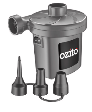
Compressors make a tiny volume of high-pressure air and use a huge amount of power to do it. This is not what you need. You need a fairly large volume of low-pressure air. 70 l/min is about 2 CFM and it'll refer to the displacement of the pump running at maximum speed. Actual air delivered during its intended use is unlikely to be much more than half that. You'd be better off with an airbed inflator. Bunnings show a mains-powered one, but you should have no problem sourcing a 12V version if that's what you need. 440 l/min is about 15 CFM, which would provide enough air to burn about 6 lb/hr of charcoal to CO2 or 12 lb/hr to CO. You can expect to burn to a mixture of CO and CO2 with primary air, mostly CO, with the CO mostly burning to CO2 with secondary air above the coals.
-
Over here in the UK, flammable gas fittings tend to be Left-handed, where inert and Oxidizing gas fittings tend to be Right-handed. I think what you are looking for is what we over here would call a "LH nut and hosetail", usually available from a local welding supplier. The hosetail needs to suit the bore of your hose and you'll need suitable clips. I use O-clips here. I'm guessing there will be something similar over there? If you have a RH nut and hosetail already, you'll probably just need the LH nut and clips.
-
First question: what are the gas jets in your current burners? Are they drilled holes, or can you swap them for smaller ones (many burner designs use MIG welder tips as gas jets)? Second question: Where in the UK are you? It's not very likely, admittedly, but there may be someone fairly local who can help get your current burners running better. In my fairly limited experience, the mistake most folk seem to make is to put in too big a gas jet. This gives an excessively rich mixture and a low flame temperature in the forge. If that is what you are seeing, there will probably be a LOT of dragons breath. Run the forge in the dark and see how it looks. If it's easy to change jets in your current burners, a weekend of playing around with jet sizes will probably see you right. If you need to buy new burners, I would recommend using Long Venturi Amal Atmospheric Injectors from Burlen dot co dot uk. Ideally, you want the ones jetted for Butane because they give a leaner mixture and higher flame temperature on Propane without secondary air. The Butane ones are all currently out of stock. The only difference between the ones for different gases is the jet size. If you are in a hurry, some of the Propane and NG Long Venturi injectors are still showing in stock, so buying one or more of these with the extra jet(s) for Butane may be a quick option. I'd guess those are currently 1" burners you have, but it's not easy to tell. I think you'll want 3 injectors sized to suit the present pipe. There is not a lot of point in recommending any other burner over here, IMO/E. However, I am just some guy on the internet. Do some research online. If you can get to speak to a smith who has tried them, to get a less partisan opinion than mine, I'd strongly suggest you do so. If those are 3 off 1" burners, it's certainly worth checking out the regulator and cylinder to make sure you are not running up against the maximum rate at which gas can be supplied. What size is your cylinder? What is your regulator? I've had enough trouble with cheap regulators that I only ever use plugged Propane welding regulators now. At 20-30 quid delivered, new, off ebay, they have enough capacity for most realistic forges, are rugged, are finely adjustable by gloved hands and have the pressure setting scale marked on the body. Admittedly the scale is not particularly accurate, but it's not far off the accuracy of the cheap gauges you find on many regulators and is plenty good enough for me. To be honest, I'm not usually a fan of gauges, largely because they are so fragile. If you must use one, the cheapest thing I've found to work well and reliably is a Glycerine-filled gauge. Expect to pay around a tenner for a 0-4 bar, 0-60 PSI, 2 1/2" one with either bottom or centre-back 1/4" BSP male connection.
-
Presumably in the UK? "PatioGas" is a proprietary Propane cylinder that uses a clip-on, non-adjustable low-pressure regulator. With its lower boiling point, Propane will work at lower ambient temperatures and higher take-off rates than Butane, so is quite popular for things like patio heaters. However, there are no high-pressure regulators available for patio gas. It is not just a case of upgrading the regulator: you'll need to change the cylinder too. Forges need the female-threaded cylinder connection found on 47 kg, 19 kg and 13 kg cylinders, so you'll need one of these. You can usually exchange any cylinder for any other cylinder within the same group, on the basis that the cylinder deposit was paid on the first cylinder. I'm pretty sure that the Patio Gas used to be in the same "group" as these, but has since been put into a group on its own (I think it's just so the money-grubbing slimeballs can make more money). If you have the original paperwork for the Patio Gas, they'll refund the deposit and take a deposit on a fresh cylinder. If you've not got the paperwork, they'll want a fresh deposit on a Propane cylinder with a threaded connection. If it looks like you'll be getting charged for a new gas agreement, it is worth looking at Flogas, who are the other big UK bottled gas supplier, for comparative prices. My preferred cylinder size is 19 kg: lasts longer than the 13 kg but is still easy enough to move. 13 kg is stocked in more places though. For your new regulator, search for a "plugged propane regulator" on ebay or at a local welding supplier. 0-2 bar (0-30 PSI) range is probably best. The plugged regs have a plug instead of a (fragile) Gauge. They are designed for use by welders, so are pretty rugged, have big adjusting knobs that can be finely adjusted by hairy-arsed individuals wearing gloves, and have the pressure-setting markings on the body. While the markings are not as accurate as a good gauge, they are about as good as most of the cheap gauges fitted to regulators as standard and are plenty good enough for our purposes. Expect to pay around 25-30 quid. There are cheaper regs about, but I feel the plugged welding regs are about the sweet-spot on the price vs performance/quality curve.
-
At startup, the forge is cold. The mixture temperature is low, and so is the flame speed. The flame will tend to stabilize within the forge. As the forge gets hotter, the flame speed increases and the flame stabilizes closer to the burner nozzle. If the gas pressure is high enough, the mixture speed will be sufficient to prevent burn-back once the forge reaches its full temperature. If the gas pressure and mixture speed are not high enough, at some point the forge will get hot enough for the flame to run down the burner tube. When this happens, the flame heats the burner tube as it runs along it, increasing the temperature of the next gulp of mixture and causing it to burn back more readily. If this sounds anything like what you are seeing, try running at a substantially higher pressure and see if the problem goes away. Gas flow varies as the square root of the pressure, so you want to at least double the pressure to see if it has an effect. I'd probably aim for 4 times the pressure to double the gas flow and mixture speed. You might need to start low and increase the pressure as the forge heats up. If it works, you can then experiment to see what your setup needs as a minimum. If it doesn't work, you can try something else (Charles at Atlas seems to have a good understanding of their kit and can probably point you in the right direction), but it's an easy thing to check.
-
What pressure are you running at? Have you tried running at a higher pressure? To work properly, the mixture needs to be moving along the burner tube towards the forge, faster than a flame can travel through the mixture in the opposite direction. If/when the flame speed exceeds the mixture speed, the flame will run back up the burner tube until it runs out of mixture and the flame will go out. Gas will coninue to flow, will draw in air and mix with it, the mixture will travel along the burner tube until it reaches the hot forge, where it will ignite and the process will repeat. The flame speed is variable and is affected by several things. Among these are temperature and pressure. Increasing either will increase the flame speed.
-
I put together a little spreadsheet a few years ago to try to show the relationship between airflow and fuel consumed. I was having a discussion with a smith who thought he wanted a bigger blower, but actually needed a higher-pressure blower. I don't think I have ever personally seen a forge actually using more than about 20 CFM of air outside of a "proper industrial" setting (Furnaces you could park a small car in and fork-lift trucks with hydraulic "hands" for manipulating the billets). 20 CFM will use a full 47 kg or 100lb Propane cylinder within an 8-hour day. I'm hoping it attaches. On the spreadsheet, the wide range of each fuel consumed for any given airflow is because I have taken the limits as complete stoichiometric combustion to Carbon Dioxide, CO2, and combustion to Carbon Monoxide, CO. We tend to run somewhere within this range (though running even richer on Propane for Heat-Treating is something that some of the bladesmiths do). I would hazard a guess that the smaller blower you are looking at has a 2" outlet and that the bigger one has at least a 3" outlet? If you are reducing the cross-sectional area to a 1 1/2" diameter, you will only get the proportional flow: 1 1/2" is 3/4 of 2", so the CSA of the 1 1/2" pipe is 9/16 that of the (assumed) 2" blower outlet and your maximum possible flow will be 9/16 x 75 CFM= 42 CFM. That would use between 13 and 18 pounds of Propane per hour. If the 272 CFM blower has a 3" outlet, the 1 1/2" pipe will have 1/4 the CSA and 1/4 x 273 = 68 CFM maximum possible flow through 1 1/2" dia. 21-30 lbs of Propane per hour. Obviously I am wildly guessing at the sizes, but if you have the links to the blower details you can probably get the information to do the calculation yourself more accurately. Also bear in mind that if your total burner port area is less than the pipe CSA, that will become the minimum area. If you are using fittings to get the fuel gas to the middle of the airstream, that might be your minimum area. Likewise if you have a baffle plate in the plenum. In reality, the flow-proportional-to-area values are still hugely optimistic because the CFM rating of a blower is based on zero pressure loss on inlet or outlet. Since we pipe the outlet to the burner, there are significant pressure losses as a result of friction in the pipe and these will reduce the flow. The main point I am trying to make is that the CFM rating of a blower, which is often the ONLY information provided by the manufacturer/seller, is not a useful piece of information for us. It's a bit like trying to select a vehicle for snow-plowing when the only information you have access to is the maximum speed. If the spreadsheet does attach successfully and anyone with any understanding of Chemistry wants to sanity-check it, I'd appreciate it: I could be completely wrong and I'd rather know. Calculation of heat produced and fuel used by burning with air.ods
-
In reality, the CFM rating is meaningless. We are much more interested at the pressure developed at the low-flow end of the operating range. Without the removed links, it is not possible to see whether the pressure is given.
-
When you look up the feeds and speeds for drilling, there are both values, feed and speed, given. "We" can usually take the speed with a pinch of salt and run a lot slower, as the values are given for production scenarios in which time is money. It is certainly unwise to run faster. The feed is important for work-hardening materials. Each pass of the cutting edge does work as it cuts and leaves a thin work-hardened layer on the workpiece. If the feed is correct, the next pass of the cutting edge will get below this thin work-hardened layer and cut the un-work-hardened material beneath. Turning slow and feeding hard with a drill-press is the best approach for most of us. Using a hand-held drill, it can be hard to maintain enough pressure to get the feed necessary. If the drill stops cutting, even momentarily, it will skate on the previously-cut surface with the feed pressure spread over a tiny area at, and just behind, the cutting edge. This high-pressure contact will cause further work-hardening and the problem will swiftly escalate. Many of us are impatient, bloody-minded types and will persist in trying to drill after the drill stops cutting. If you have no option but to use a hand-held drill, use the slowest speed you can, watch the swarf and IMMEDIATELY stop if the drill stops cutting. Either sharpen the drill (a skill that is well worth acquiring) or replace it with a new one, then start again. IME, the only "better"/harder drills that work well in a handheld drill are TCT drills intended for use on Stainless Steels (which work-harden very readily) or Hard Plate (here in the UK, I've bought them from locksmiths when I've run into the problem when out on sites, but they really know how to charge). Cobalt drills do work a little better than vanilla HSS, but they also tend to be more brittle. The improvement is significant in a rigid setup, but there is a high probability you'll just break them in a handheld drill. Solid Carbide is even worse for breaking when used in a handheld drill (though truly superb in a rigid setup). The TCT ones have the hard tip, but a tough shank and flutes, so are a good choice in a handheld drill.
-
Although the "obvious" thing to do is to look for "better"/harder drill bits, the problem is not usually with the drill bit, but with the rest of the setup, In My (limited) Experience. Very few handheld drills run slowly enough for drilling hard steels. The hardness problem is not usually "just" the hardness of the steel that is about to be drilled. Work-hardening often enters into the equation as well.
-
I think the way that the IFBs fail in a forge is down to the extreme temperature gradient when the forge starts. I think the hot face gets hot fast and expands, putting the cooler material behind it under tension and starting cracks. When the forge stops, the "hot" face cools quickly, contracting while leaving the warmer material behind it expanded. This puts the cooler material under tension and the cracks propagate from within the IFB material to the surface. In industrial kilns, the rate at which the temperature rises is much lower, the temperature gradient is much less and the cracking problem doesn't really arise. Because IFBs are intended for industrial applications, there is no information provided by the manufacturers on their resistance to rapid thermal cycling. The only information "we" tend to get is anecdotal from others of "us". Unless you have another, better, use for the bricks, I'd say use them for a forge and report back on how well they work.
-
It is certainly burning. It looks rich: there is a lot of secondary flame, but that should be adjustable once it's in a forge. Do you know what is causing the flame length variation that is apparent in the video?
.jpg.f879309d75800dd5fc5b1eec39b9a232.jpg)
.jpg.fc7d9856099db8753bb45b36b9efe8b7.jpg)
.jpg.e6676387e11ba40bfc05d24cd0517569.jpg)