Alan Evans
Members
-
Joined
-
Last visited
Everything posted by Alan Evans
-
Thank you for the kind words. The holes were left as punched, no cold sizing! Straighten all bars to start with meticulously, and calculate the dynamics of the hole movement/bar length for the various cross sections of bar. My furnace design gives me a regular heat expansion and I made an end stop system with a loose piece for clearance. Should have a video of the punching somewhere. I did do a write up for the BABA magazine and do have some photographs of the making of the Bigg Market Gates...I probably will be able to find it on some hard drive somewhere, if I do I will post it on another thread. Alan
-
The smith I learned from used scroll wrenches and needle nosed tongs to form the scroll around the jig. Most of the scrolls I helped him with were from the Davies Brother's gates at Erddig House. They were mainly rolled snub scrolls. We forged the taper and rolled the snub, and started the scroll freehand. The snub then hooked over the end of the jig and was largely self locking. I am sure there is a photo sequence in the Cosira books that may help. I have to agree that the scroll jig is awful...as with any jig if you do not get it right there is no time saved at all. The jig must be as near perfect as possible in order to balance out any minor variances you build in when pulling the scroll around. A bad jig just means very one of the production run is poor. Alan
-
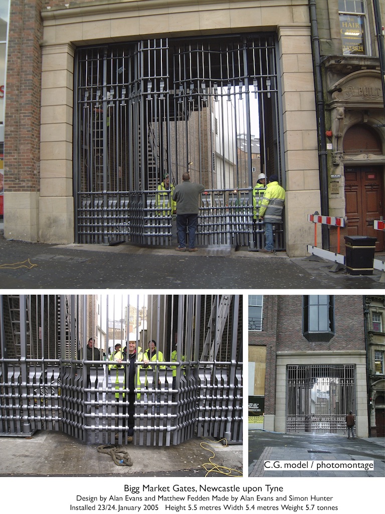
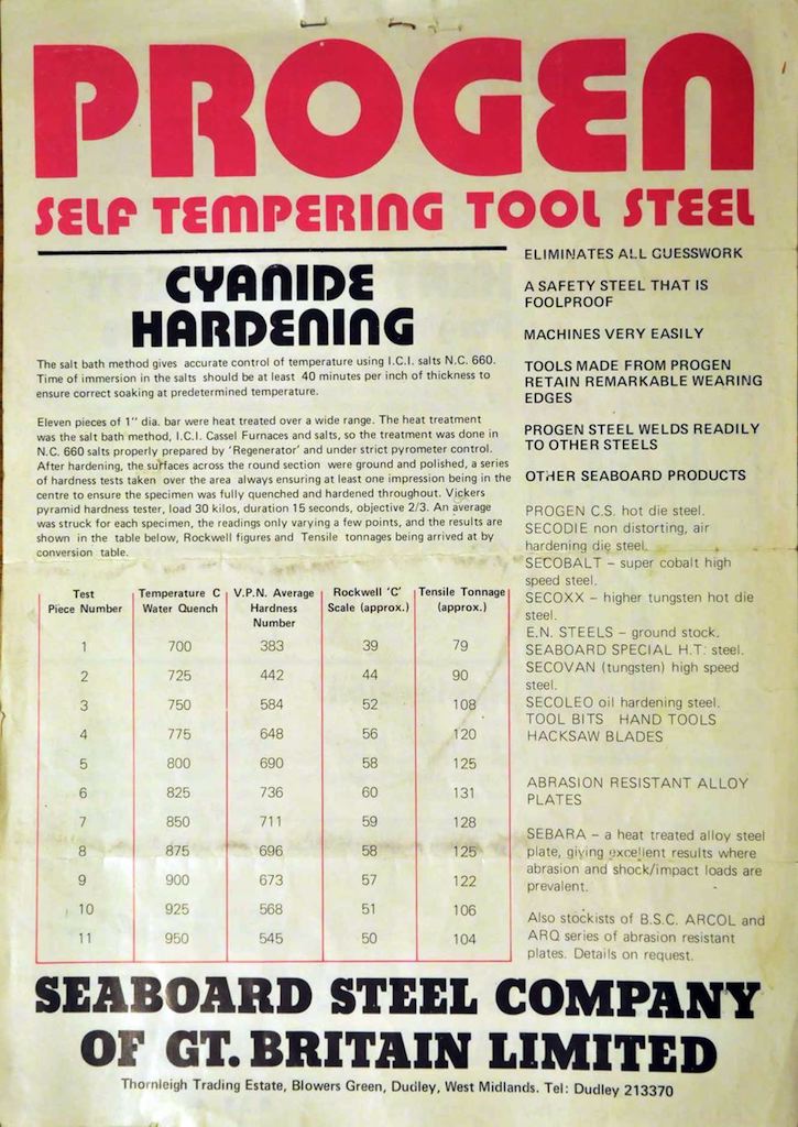
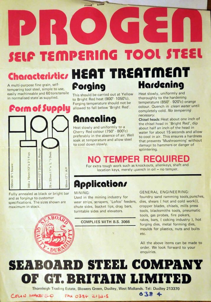
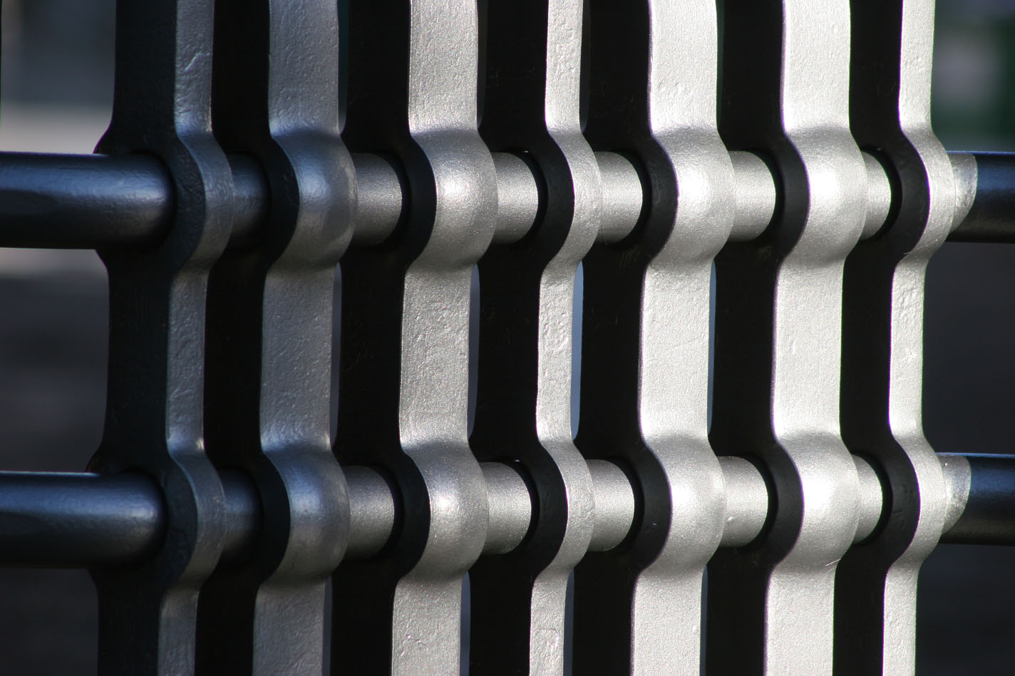
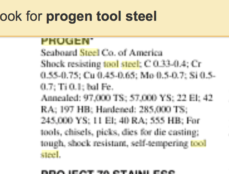
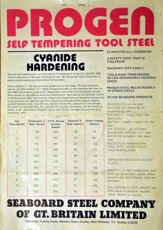
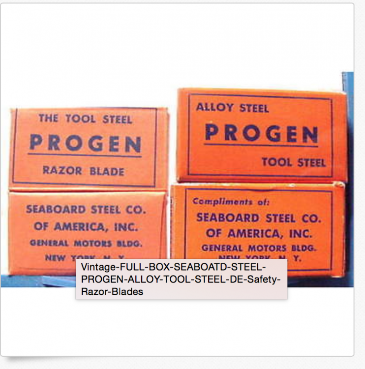
Progen, oil quenched, no temper. It is no longer made I understand. I happen to have a tonne of it bought just before the end of a good financial year...still got most of it! I think you have a near equivalent in the Flutagon military field tool steel. There was a thread some time ago which had some info about it https://www.iforgeiron.com/topic/44724-hot-forging-punches-material-treatment/#comment-463081 Progen is very forgiving and tough. Hard and fine grain enough to make razor blades! I sent Hofi the punch design and he had some made out of solid carbide which must have been great. Lower friction and no deformation. With my Progen ones I started off making them with a flat bottom and was paranoid about keeping it that way, sanding them back to profile after every two or three holes. After a few holes they round out and build up a mushroom end. After a few years I learned to relax about it, and do not bother to ever dress them now. The funny thing was that I noticed with a mushroomed end they released a lot easier on the upstroke...there was only contact on the sides of the mushroom, and not the friction of the wedge engaging with the entire thickness. I also realised that the mushroom was not the punch deforming but layers of mild steel from the workpiece welding themselves to the punch...they would build up and then come off and the punches never got shorter! Hofi's carbide ones would probably just stay the same but the softer Progen turned out to be fine. I developed the punch, the hydraulic system and the furnace for the Public Record Office commission. 12metres wide plus side panels...A lot of holes which had to line up! It made a huge difference for production.From two men getting 16 holes done a day with a coke fire and power hammer, with some of them going awry...to one man doing 42 holes in one day with every one accurate length and centred. The punch system was also used on the Big Market gates and that was all quite heavy stock. As the movies say, no punches were harmed in the making of these projects. Slightly over the top given the thread title, but you asked! Alan


-
You would be very welcome, in fact if you are here within the next hour I will set another place at the table, I have just been informed we are having venison stew! I agree! Along with our vegetables in its tummy...that is why I bought a rifle, crop protection...I reckoned if they were going to eat some of Lesley's wonderful organic produce, it was fair enough that we should eat some of them. Alan
-
It is offally good. I would send some over to you but it does not travel well. Alan
-
I haven't had Moose, not a lot of them around here....but we always prize the liver from the Muntjac, Roe and Fallow that I shoot. Flash fried...heaven. Alan
-
Is Monel used for medical tools? Never knew that. I thought they were for lifting stuff out of a boiling water steriliser (Autoclave?) like jars and bottles when bottling fruit. Alan
-
If you have a couple of cross pein hammers, you could crown one along its length and radius the very ends so that there were no sharp indentations on the work piece. Each hammer blow is then overlapped to give a continuous spread with no cold shuts. Each blow would leave an elliptical mark. The tighter radius of the minor axis would still be acting to spread your metal sideways. Alan
-
Forgot to say that of course the above punches are for the hydraulic press which has a Ø1.5" chuck. So they do not go straight through like the ones you used. I have made some like that, but if I need a longer slot I tend to do it with two tools, a dedicated slot punch and separate drift. I also refer to these as slot punches as opposed to slit, these punch out a slug whereas my slitting chisels are sharp edged and do not remove any metal, just cut through it. Alan
-
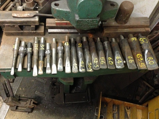
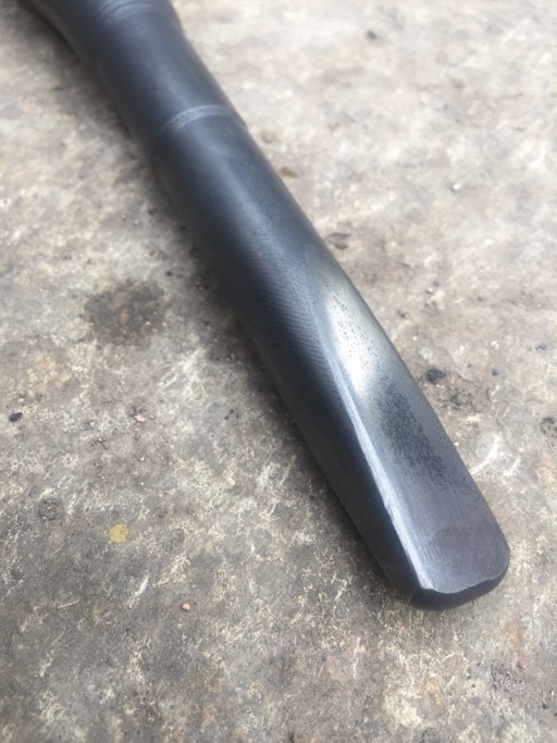
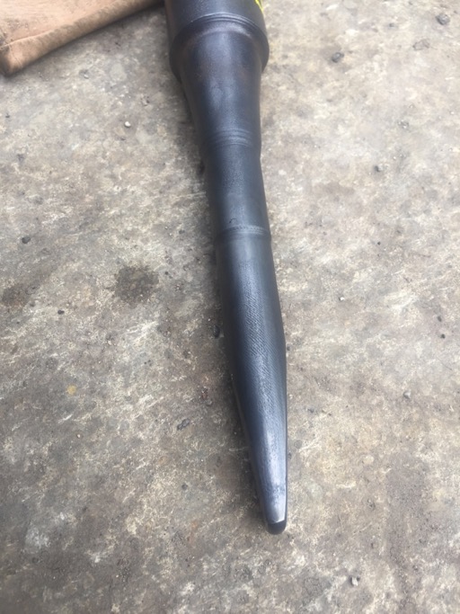
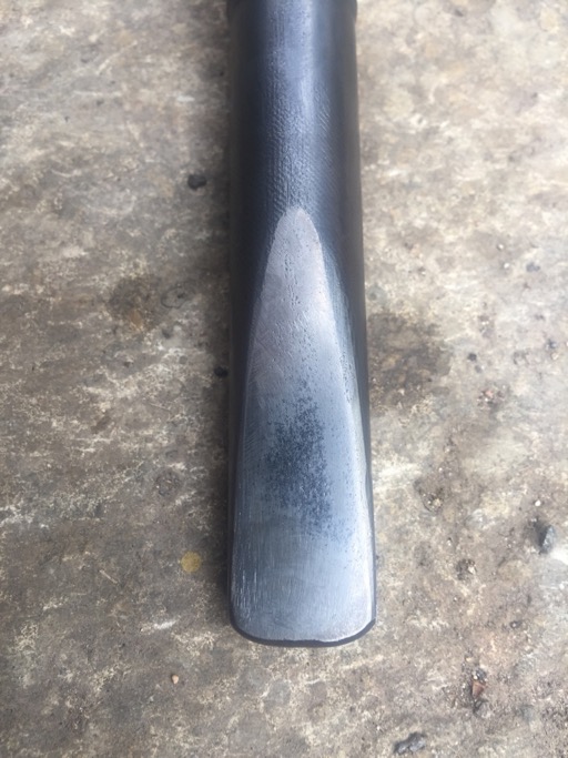
Hi Andrew sorry it took so long, went away for a few days over Easter. Herewith the punch profile I use. The important thing about the punch and drift combination is that the tip width/slot length is the same as the final diameter...you can see the sides of the the punch are parallel top to bottom. Otherwise you cannot get it out! The form of the punch is fairly simple you could make it just by stock removal...I always forge them because it quicker, and then I have the heat for an oil hardening. The tip is radiused in both directions. I normally just make them flat and relieve the corners. The heat/wear of use takes the corners off and radiuses the punch and they become more and more efficient. Having reached the optimum heat conducting profile they do not deform any further. I have explored a number of different transition profiles over the years. Rectangles with rounded ends through ovals and ellipses but the common rule for all of them has been to ensure there are no sharp edges or corners, everything is radiused. In the photo below you can see some of the variations. There are a couple of facetted ones that drifted out to an octagonal hole. The wedge facets have been both flat, convex and concave and soft facetted but makes little difference. So the more recent ones are simple flats. The concave surface does help release the punch on the big punches going through 60mm (2.5") square and up. Alan
-
Think rolling pin profile for either hammer or anvil or both, and how you roll out pastry. The pastry always moves at right angles to the axis of the pin. If you just push the rolling pin down rather than roll it (mimicking the impact of a cross pein hammer, fuller or anvil horn) the pastry still stretches in the same direction. So will your metal. Alan
-
I made an old woman's tooth for my little 360 bobcat from 50mm (2") square mild steel and just tipped it with 312 rod. It was not for roots but breaking up the limestone layers in the bottom of the trench. Your actual hook and carriage just need to be strong enough to take the pull, so can be made from mild steel rather than needing anything stronger or more exotic, the back hoe won't mind if is from a heavier gauge softer metal or from a lighter and stronger alloy. The cutting edge is your only need to have something hard and keep a sharp edge. I would be inclined to modify a bolt-on bucket tooth. Which will hold an edge and can be replaced easily if it ever did fail. A welded on lump of Hardox bucket edging could also be used for cutting edge. Alan
-
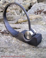
Looks like it was for lifting and aligning the end of a horizontal axle, pole or pipe. Something that required fairy precise levelling given the pinch bolt adjustment for start and stop. It only provides a couple of inches of lift. Could it be a basic tap control for irrigation? Lift the pipe and tie the lever handle to pipe for off, untie and let pipe down for on? Rather than lifting the ring could it be for pushing the base plate down? The ring would have to be horizontal to the ground to be a post puller, and the inverted U legs of the stand would indicate the end of a horizontal item being lifted could poke through... An axle jack?... but you could not get it off after you put the wheel on. Lifting mill stone spindles? Alan
-
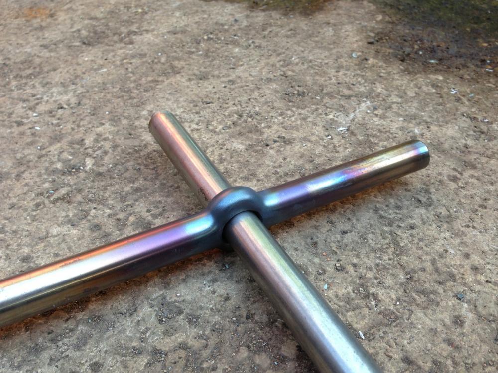
I use a combination slot punch and drift. The long axis length of the slot punch is the same as the final diameter (or long axis if left oval for a handle) of the hole. The width of the punch is a narrow as you can get away with. With Ø3/8" parent bar you really need to to be less than 1/8". I profile the punch end with a tight radius so that it acts as a fuller and spreads the metal to either side without elongating the bar. Thus keeping as much metal either side of the hole as possible and obviating the need to upset. If you wish to pass a larger diameter bar than the parent through the hole you must use a longer punch and allow for the bar to reduce in length. You would make life a lot easier for yourself if you used 3/8" square and then octaganise or round the head and pein after punching the hole. With round bar you need to start off with the bar in a swage, and I quite often create a flat spot with a full faced hammer or punch in order to create a facet for locating/starting the punch. This was a Ø21mm clearance hole through Ø20mm (Ø3/4") 316 SS made with the same proportion of slot punch. Any larger diameter hole and there would be a noticeable wasting of the metal where the hole meets the parent bar. Alan
-
JHCC's suggestion is the Rolls Royce version, and would look best / closest to the original. If you do not to want to put in the time for piercing the complete backplate, the strength of support for the actual break would be achieved with less than an inch of brass either side, sufficient to get a good bond. You could then use further strips top and bottom to maintain the plane of the backplate against the wall... Based on the "make a mistake...make it a feature" philosophy....an even simpler solution would be to mount the two pieces of iron on a back plate/shield. A glass mirror, a panel of wood, stainless steel or brass the size of the blanket background in your photograph neatly chamfered, to suit the position and room decor. Mirrors and mirror polished brass and stainless steel are often used as reflectors to enhance the candle light. The TIG rods I use for dissimilar metals are either 29/9s, 312 or 23/12s, 309. I have found the 312 works really well for all sorts...tool steel hammer pallets, mild to stainless, even silicon bronze to stainless. I found them far better for dissimilar than the stainless specific 304 or 316 rods. Indeed great for everything...apart from cast iron, I have never had success welding it. I will only go for silver solder or braze for that now. But I would not attempt to solder, braze or weld your piece for fear of further damage, you do not know what other areas were strained before the break happened where it did. There may be cracks running parallel to the break on either side... A backplate reinforcing of some sort using glue is definitely wise. Alan
-
I was always taught that it was better to give than to receive. Alan
-
Interesting...never noticed that link before...is this just idle conjecture, or do you have any supporting evidence? The nearest I have come to lathe in that context is when dealing with our old cottage walls which are lime and horse hair plaster on lathe. Foul job if you have to drill or remove bits...dust everywhere. Definitely gives one a good excuse to get plastered with a few too many bottles of beer afterwards though! Alan
-
The key thing about trip hammers and tilt hammers using water or other power to lift the hammer....whether they just rely on falling weight or spring assistance for the blow...is that they are lifted by external power. You don't get energy for nothing, so if you are relying on leg muscles to lift both hammer head and the spring assisted return, you are getting no advantage from the system. You have lost the direct control and sensitivity of variable blow weight, and are still having to push down on treadle just as hard even if you only require a light tap...which you would have to gauge by the length of treadle stroke and hammer arc length...rather than just by the direct and intuitive adjustment of push power. All the Oliver hammers I have seen in the chain and nail making shops...were treadle down and spring return. The less sophisticated ones were a plank or forked branch on the ground with a chain, rope or leather strap going to the hammer shaft to bring the hammer down. Another strap going from just behind the hammer head up to a plank or pole spring wedged in the rafters of the roof for the return. Identical configuration to a chair bodger's pole lathe. Alan
-
The quality of the 2D video looks excellent. The 3D one on my Mac laptop plays two side by side images in Safari but in Chrome puts them both together with the colour halo. The 2D option of the 3D version in Chrome does not appear as sharp and clear as the 2D version. One thing I did with the three prong toast forks I used to make, was to pre-forge the taper of the tines before splitting. Do the bulk of it in one piece and then all that was needed was to just regularise and chamfer the tines afterwards. I found it was easier and quicker to forge in one piece, and with fewer heats once split, there was less risk of burning the tips...though I found you could still burn them if you tried hard enough! Different starting and finishing points of course. I was forging from Ø16mm (Ø5/8") and leaving a 3D knop at the root of the tines. The tines of course came out of a much shorter section of parent bar, so needed much more drawing out. Have you ever tried that? Alan p.s. Added this to the you tube feed back, as requested.
-
You should be able to if it is an electric hydraulic, if its electro mechanical, using a screw thread drive, probably best to leave it as is and try using use it as a screw drive press. I have a 12 tonne single acting press a 30 tonne double acting press both vertical and a 100 tonne single acting horizontal. I have a double acting hydraulic ram log splitter than runs off the auxiliary pipes on the tractor or digger which was sold as 5 tonnes. All much the same mechanically. The guide system on the log splitter is pretty sloppy but could be improved easily. The 12 tonne press I use without a guide and rotate to align the tools by eye, the friction of the internal return spring keeps it from rotating on approach. I often just use a hammer face block on the ram end and hand hold power hammer tools so alignment does not matter then. The log splitter has a wedge blade welded to the ram, the big horizontal Finlay has an Ø8"push fit peg into a radiused nose block, which allows the pressure plate to swivel and reduce side thrust onto the ram. The two vertical presses have simple pinch bolt chucks like a fly press machined into the end of their rams, the 12T Ø1" and the 30T Ø1.5" It would not be difficult to replace the splitter blade wth a chuck or add one on, clamp to the blade...you probably have plenty of stroke length. Not quite so simple if it is one of those electric splitters with a fixed blade and a pressure plate on the ram, but still doable. What tonnage rating is your electric splitter? That is likely to be the most limiting factor of the conversion. My large flypress is a no.8 and the smaller one was a no.4 but that was quite capable of straightening bars cold and forming bowls. No electric cable runs underneath where hot scale could sit on it? A lot of the splitters sold over here now have safety systems that require both hands on the controls, that would reduce the usefulness of the tool somewhat...Can you convert your splitter to a foot control so you have both hands available to manipulate tools and workpiece? Alan
-
In the Black Country, the home of chain and nail making industries, the blacksmiths all kept Staffordshire Bull Terriers as fighting dogs...the breed became known as the blacksmiths' dog. The family I stayed with when training had one and it was amazing how it could lie on the hearthstone of their inglenook fireplace with its feet almost in the fire. The Staffys also gave rise to the old Black Country chestnut, which sounds best in the dialect.... "I've got a blacksmiths' dog" "How do you know it's a Blacksmiths' dog?" "Well if you kick it up the backside, it will make a bolt for the door!" Alan
-
Drifton Forge do you mean punching on the arras...the corner of a bar, as Iron Poet and John have understood, or at an angle other than 90˚ through a bar? Alan
-
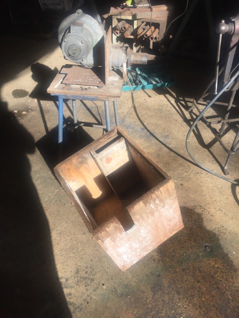
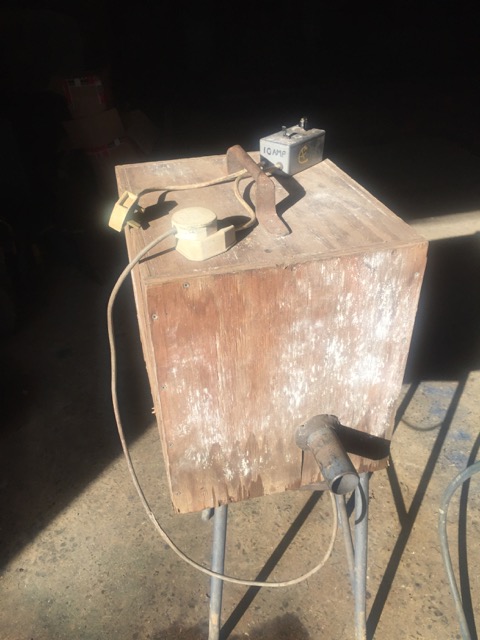
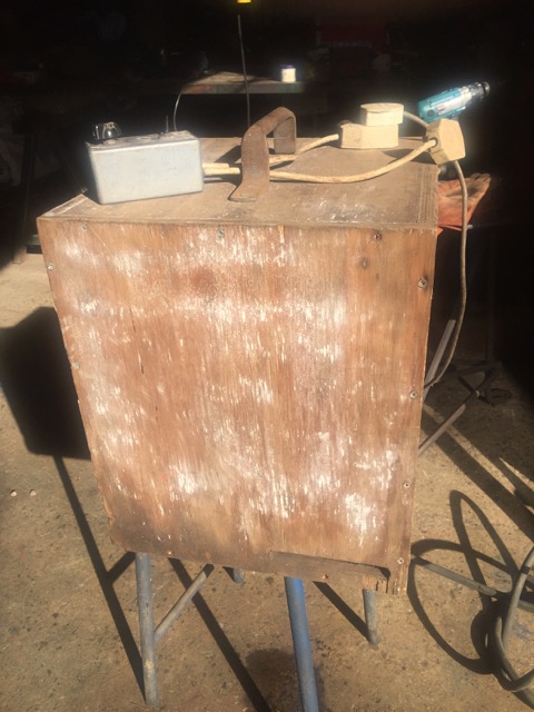
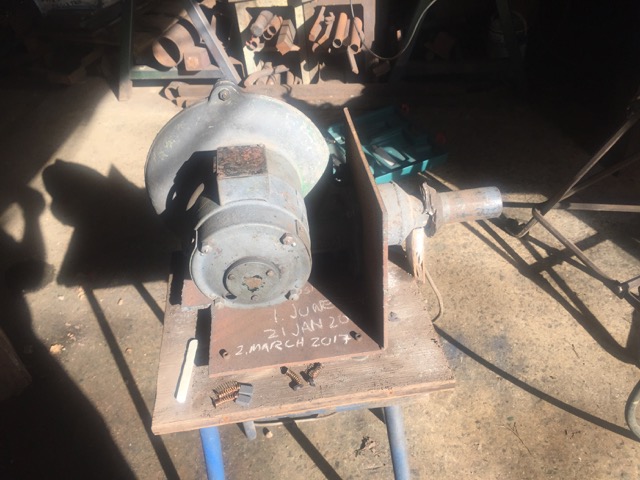
All my fans are in boxes to hush them up a bit. The big one has a 1hp motor and a 24" fan (at a guess) and is quieter than the cooling fan on the MIG welder...mind you that is an old 500 amp beast. I replaced the brushes on the little fan a couple of weeks ago and took some photos of the box with its internal baffle/flue...may be useful for someone... Alan
-
The resentment I feel with presbyopia and varifocal lenses is childish I know...so many people have not had the benefit of 20/20 through the rest of their life. When I finally acknowledged that my eyesight had deteriorated and that reading glasses and non prescription bifocal safety glasses were no longer adequate I went to the optician and ordered a couple of pairs of large aviator style safety varifocal safety glasses. My idea of the big lenses, apart from maximum protected area, was to enable them to be mainly clear with the graded magnification starting below the centre point. So at the anvil I would be looking through clear glass. It didn't turn out that way. When I put them on in the shop the optician said it will take a bit of time to get used to them. I thought, what does he know? They look fine. Thought I would leave them on, said thank you and goodbye, and as I went to open the door missed the door handle! Lesson one! Then I got back to the forge I thought I would have a bit of a tidy up. There was a a 600mm offcut lying on the bench so I picked it up noticed it had a curve. I tapped it to straighten it using the correct position on the anvil and the right weight of blow based on 30 odd years of familiarity...and got a shock that it was now bizarrely over-bent. Then looked along it, and discovered it had been straight until I tapped it...some head scratching later I discovered that the glasses distorted horizontal lines...into a frown if they were above eye level and into a smile if they were below. Tilting my head up and down made them cycle! Lesson two! Straightening long bars in the press with natural eyesight was so easy, by being able to look along the full length of 3 or 4 metres...I have to consciously alter my head angle now to focus at the different distances using a good light and it is just not as efficient or accurate...hey ho. Getting older with bits wearing out is a pain. But it sure beats the alternative as they say! Alan ps these sort of thing might help some people on a short term basis...while waiting for your prescription ones...cheap enough and being 3M should be available most places. http://www.axminster.co.uk/3m-bx-readers-bifocal-safety-spectacles-ax866756
-
Plaster of Paris and tallow is what I was told to mix in with the pitch. I am sure that the metal won't mind what you use! Apart from the balance between flexiblility and support the only other consideration is the release from the metal surface when resetting. Alan