
Alan Evans
-
Posts
1,990 -
Joined
-
Last visited
Content Type
Profiles
Forums
Articles
Gallery
Downloads
Events
Everything posted by Alan Evans
-
You are forgiven! The simplicity and robustness of the fixed hook on the push-pull ruler is well suited to dealing with hot work...no possibility of jamming in the wrong place with the heat, and being in one piece, rather than a number of small mass elements, conducts the heat away better. However the added point you made about adapting the principle for other tools reminded me of the removable spacing blocks I use with an end stop on the saws or press. When I am punching in the press using an end stop...my small furnace gives me a repeatable 150mm (6") heat...I set the end stop 12mm over length and use a loose spacer which I slide the workpiece up against, lock the position and remove the spacer before the operation so the the end of the bar does not drag on the endstop. On the saws using an end stop when cutting a series of pieces off. The spacer block is useful to prevent the cut piece from jamming between the blade and end stop or fence. Alan
-
I took the protractor head off mine (which was not the proper original one) and made a higher and longer one from 100x25mm (4x1") which I set with a square reading off the teeth of the blade. Alan
-
Yes I quite agree...but we still have not heard from Natenarron whether the problem is in the angle of the vice to the blade i.e inaccurate when looking down on the cut or whether the cut is not coming down vertically through the workpiece which is where your point would come in. Alan
-
Ahem... Alan
-
Ah, I think you are talking about using the bandsaw in a vertical position like a wood one with a table. I thought the OP was talking about using it in the horizontal position with the vice as a cut off saw. My old Elliot will do both. You can bolt a table onto it when it is lifted into the vertical position like in the OPs photographs. Which is it natenaaron? A problem in vertical or horizontal mode? Alan
-
Are you expecting too much precision? Have you contacted the owner to compare notes...get him to come and set it up. Are consecutive cuts parallel or is it wandering erratically? If the cuts are constant you should be able to adjust alignments to present the metal square to the blade. Is it cutting vertically or wandering sideways as it goes down? How did you set the tension on the blade? If over tight you may have flexed the frame and taken the idler wheel out of line with the main spindle. Is the section of the blade between the guides straight? If it has a twist in it...as the carriage drops the contact line of the blade changes. On my saw the guide rollers are mounted on a block which can be rotated to adjust any twist out. Have you set the fence/fixed vice jaw perpendicular to the blade, and checked it is still square at different heights through the drop arc? Is it the right size blade for the saw? I was given an old Elliot saw years ago, which I still have...lovely old thing...It came with a 1/2" blade fitted and a roll of Starret 1/2" blade which I would cut to length and splice into loops with silver solder. I used it for years like that. It was not very accurate...until I visited a friend with the same model saw and realised that it was designed for 5/8" blades...all the time the teeth had been going through the guide wheels and of course the back edge of the blade was not guided at all! I just assumed it was the correct blade and that is how it worked! Hey Ho. Alan
-
The links stopped working after a forum software update a year to two ago I think. Admin are aware of it, but have not asked us to repost the lost images. Presumably Glen is still paying for their storage on the server while the software suppliers are trying to fix the directory malfunction. Alan
-
The people at Dama steel put two powders together to get the patterns they produce...I presume it would look like one of those novelty glass tubes with different colour sands from deserts around the world before they fuse the it. The description of the process indicates that the powder grains are rather small...I wonder how they make the powder? Alan
-
Trouble with steel wool or swarf is that it is mostly air by volume almost impossible to squash it tight enough to keep oxygen out of the canister. Have to evacuate or fill it with inert gas prior to sealing. Seems an awful lot of energy has gone into making the steel, converting it to steel wool, and then trying to convert it back again...maybe rethink and cut out the middle man... Alan
-
The powder steels are made in canister. There may be some information on the web. e.g.:- "Damas steel, which looks like traditional Damascus but is a tremendously strong, super-material created by bringing together two powdered steels in a nitrogen vacuum. Read more at http://www.thefield.co.uk/shooting/most-expensive-guns-26087#C440TO1seT5WKL6P.99 " But as Smoothbore says....possible aint' the end of it. Although it may be possible but then again getting to the moon we know is possible...whether you can afford the development and process infrastructure cost who knows? The powder steels are very expensive...if it was simple and cheap one would presume it would be made by many. But why not crush a load of swarf from different grades/carbon content steels in a container and get it hot and find out for yourselves? Have an adventure! Alan
-
The hook allows you to register the ruler quick-n-dirty when the metal is hot so the ruler itself does not get hot. My angle iron version also gives a flange which has not been in contact with the heat to grab. Chisel marks or paint pen marks are fine for most hot work scenarios. I find you are often wanting to make all components the same as the last one, rather than to any arbitrary dimension system. Alan
-
Alan
-
I am sorry to hear that news. I will miss his helpful contributions to IFI. Alan
-
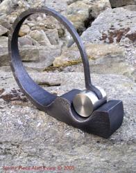
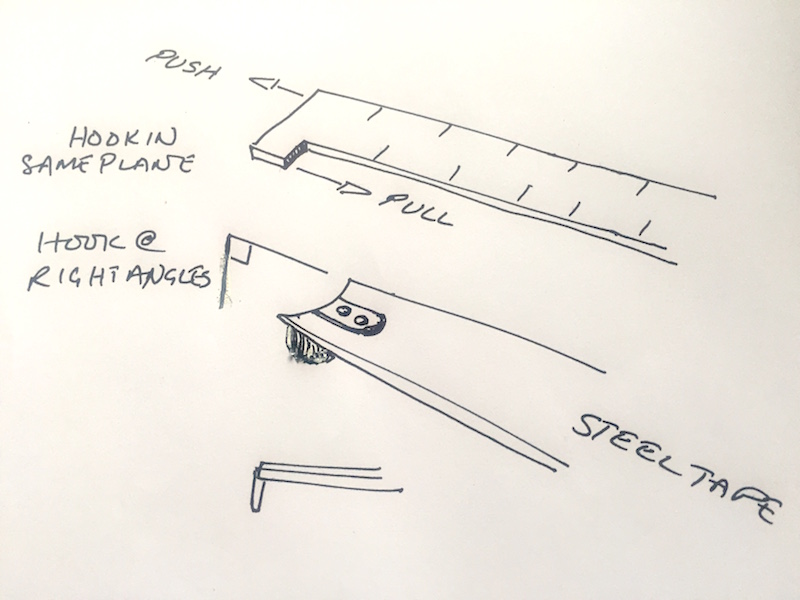
This disappeared first time around... It is not a sliding rule...nothing moves. It is just a brass strip with a hook on the end...sort of a precursor with a similar function to the sliding hook on the end of a steel tape. The hook is in plane with the ruler rather than at right angles to it as per the steel tape. I have only ever seen home made ones. Clifton Ralph shows one on his power hammer videos. My sorry version is just a bit of 20mm (3/4") angle with a tee piece welded on the end. I mark up the lengths required for the process with paint pen/white out/french chalk for an instant tell tale. Bit like the wood worker's tally stick / measuring pole made for each piece. Alan
-
Handy for hot work measuring is a push-and-pull brass rule. You can make one accurate enough for forging...it has a lug on one end which has a scale starting from the inside for when you hook it on the end of a bar...and one scale from the outside of the lug for when you push it up to a shoulder or similar. Alan
-
I used to pickle in Phosphoric acid which speeded up the wire bushing time but then you had to make sure the alkaline and rinse was dried out. But I did try other systems for the same reason as you. I have only ever used wet tumbling or rumbling systems. Certainly I would be looking to contain any dust rather than releasing it to your lungs. I made a plastic pot tumbler when I was silver smithing and jewellery making and that is similar-ish to yours. The axis was tilted off vertical rather than horizontal like yours though. I mounted that on an old record player turntable which was tilted at about 33˚ and rotated at 33rpm! It was also about 33% full. The media I used was snippets of silver and a splash of washing up liquid in tap water. If you have got enough odds and sods of steel offcuts I would just use those. Probably the simplest tumbler for metal finishing is a concrete mixer. Horribly noisy unless you can rubber line it...the best I could do was spray the out side with motor car stone chip stuff...slightly rubbery with a smooth dimpled surface which helped soften the rattle no end. I did have a commercial rumbler at one time which was a huge rubber lined pig trough on springs with an eccentric weight on the attached electric motor shaft. The whole thing weighed almost two tonnes. I used granite chippings and stainless and mild steel scrap again with water and detergent. I did eventually try the proper (commercial) ceramic media and tumbling soaps. They did not make the metal look any better, but the granite chippings broke down and formed a slurry quite quickly. The efficiency of the process depends on the tumbling action of the media and workpieces obviously. You might find that your horizontally mounted unit will rotate with the media just sitting in the bottom and not tumbling...it is why concrete mixers have fins inside and why the commercial brass finishing tumblers were wooden octagonal vessels. Before you put in ribs try tilting it at various angles to see at what point friction takes over from gravity. One other advantage to tilting it off vertical is that the lid is then just needed to prevent splashes rather than being under pressure all the time, and you do have the option to look in while it is rotating and add or remove stuff with ease. Horizontally it is going to be a bit difficult to load. The big horizontal hexagon drum version I got part way through making had an access hatch on one of the sides...I gave up when I could not get the drive slow enough and bought the rumbler. I should add that having gone through all the experimentation I found that the wet tumbling was a pain...you had to rinse off any media gunk and with mild steel dry it effectively before waxing...almost as labour intensive. My preferred finishing system for domestic steel work is now shot blast with Chilled Steel Grit or Aluminium Oxide, rotary wire brushing/burnishing and Renaissance wax. Alan
-
welding and bifocals/progressives
Alan Evans replied to natenaaron's topic in Welding/Fab General Discussion
I went through the same sequence....Do try one of the mask fitted magnifiers, for a minimal outlay you will find the return well worth it. You can always use it as a bench mounted lens if you need it for fine detailing.... Alan -
Cheating? One man's "cheating a little' is another's... common sense, logical production sequence, best practise, knowledge from experience... It is my "best way to get marks out is not to put them in" mantra. If you want to end up with a decorative textured surface on a bit of metal, you make a textured face tool and drive it in. Exactly the same process applies to wanting to end up with a mirror polished surface...why would you use anything but mirror polished tool faces to forge and form it? At the initial stage of spreading the spoon blank, if every blow is from a mirror polished hammer onto a mirror polished anvil you are not creating a rough texture which has to be removed later. By cleaning and polishing the flat blank while both sides are readily accessible, before sinking the bowl with mirror tools, there is little finishing to do afterwards. Cheating? It makes good economic sense. To my mind at least, it makes for good aesthetics. A piece fresh from the forming tools without losing definition through too much sanding and polishing processes is crisp and vibrant. Alan
-
If you are wanting to do demo work power-free for any historic enactment reason...then emery-, sand- or wet and dry paper is hardly legit either! Loose sand and a leather or cloth pad is though. Chainmail on a leather pad or glove palm was used for burnishing. You also have this wonderful by-product of forging...iron oxide which gathers around the anvil...and makes an excellent abrasive as it breaks down it gets finer and finer. Try just rubbing your hammer face in it... As I said above the best way to get marks out of metal is not to put them in...this applies at every stage of every process, so wire brushing to remove scale every heat between fire and anvil so that you do not pound it in to the surface is important. To refine the metal surface and reduce any scale, the last pass over with the hammer should be at black heat. At red heat the oxide is harder than the metal, and is pushed into the surface. At black heat, and cooler, the metal is harder than the oxide and the hammer cracks up and dusts off the oxide.... Having reduced the scale with the hammer, pickle with vinegar or hot lemon juice and dip a damp/wet cloth in the iron oxide and use as a polishing cloth. Speed and pressure help...a strip of towel one end held in the vice or nailed to the bench, hold the other and place scale flakes on the band rub the convex surface of the spoon backwards and forwards along it. A bow-drill with a string or cloth or leather mop head and sand or iron oxide to polish the concave face of bowl.... Alan
-
Well now....if you take that out of the hardy hole...use it as a top tool and drive it down on to your clean (finished surface) spoon blank over a wood block with a heavy hand hammer (foot-hammer, fly or hydraulic press if you have one) it will form the spoon without any ball pein hammer bruises. Start on the edges of the spoon and work in to the middle. Work in ever decreasing concentric circles spoon bowl shapes in order to avoid buckling the edge. Any glitches pop the new tool back in the hardy hole and true up the bowl with a mirror polished planishing hammer or hide or wood mallet, depending on the nature of the glitch. Any buckle smooth them from the centre out toward the edge...try and unbuckle/unfold them rather than tightening the fold. Alan
-
The best way to take marks out is not to put them in... Rather than using a ball pein and sinking the spoon bowl with a lot of little dimples...which then have to removed by planishing or dressing out...think about using a spoon shaped top tool which can be driven in with your hand hammer. It is lot of wasted work to put marks in. You spend much more energy straightening out the dimples than you do actually forming the dishing. The metal has not got to move far so will go fairly readily with a bowl form. Always do the edges first and work into the centre rather than thump in the middle and buckle the edge. Alan
-
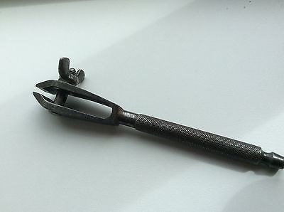
Like a giant pin vice? As Thomas says pounding on the spring not ideal. I can't see why the moving jaw has to be pivoting on a through pin though. If the jaw bottom was just located in a socket so it would not kick out sideways, and with a radiused (to the jaw length) tip to roll in the socket bottom it would work fine, and could easily be built robustly enough to take more of a pounding than the normal max. Ø20mm (3/4") pivot pin. Interesting that Diderot's fig. 18 in Thomas' illustrations shows the moving jaw to be riveted fixed with two rivets rather than the single pivot! Don't necessarily blame the Artist...in between the artists sketches and final illustration there is also an engraver or etcher working back to front to make the plate for the printing press... What a wonderful fuller faced anvil...fig.1 in Gergely's Art du Serrurier image...I fancy one of those. Alan
-
Well seeing those photographs it looks a bit obvious to me...you still have not removed the extra toolholder/chuck (as both JohnB and I have suggested)...and set your tool directly into the slide. The round tool holder is the main cause of reducing the working height and stoppable stroke length of your press. If for any reason you are not wishing to remove it... then just use a loose U shaped spacing/kissing block under the adjustable stop, as Thomas suggested. Alternatively if you are always going to be using the press like this, the kissing block can be made permanent by welding a collar to the underside of the adjustable stop. Your bottom plate pins are very wide spaced if you are trying to achieve a right angle bend. It is by dropping in loose bars between the fixed ones, as I mentioned above, that you can instantly change the dynamics of the tool...but as you say you know all about using fly presses! Alan
-
The other simple starting thing to do is remove the tee slotted rectangular base plate and use the machine base. As far as I can tell after re-reading the dimensions you quote you are including the round tool holder in the slide. Removing that, if you have not already done so, will free up more working space. The tool holder and tee slotted base plate shown are not part of the original machine. I paid around 300 pounds for my no. 8 fly press...complete with stand and some sheet metal box/control panel tooling. My 12 tonne single acting hydraulic press cost 350 ten years later. I hardly ever use the fly press now... Alan
-
In order of simplicity and economy... 1, Move the bottom pins closer together to get a tighter bend from a shorter stroke. Use swivelling bottom pins with flats to reduce any bruising. 2, Use a hand held/interchangeable top tool nose. e.g. a half round to start the bend, full round and half round on a square spacer and etc to complete. 2, Make your base tool two-stage...two pairs of pins at two different heights. You can do an initial bend then move the part-bent workpiece to the higher pins to tighten the bend. Obviously with a double length top pin. 3, Make swivelling pins with extended flats which can act as a cam action and over bend, (lots of work and head scratching). 4, Get a bigger fly press, or even better, a hydraulic one with a much longer stroke...you know it makes sense. Lots of possibilities...I often use a bit of 12mm (1/2") plate with a couple of Ø40mm (11/2") pins welded to it, I don't fix it down...it is self-centring. I then drop in one or two or more rounds to reduce the gap/centres if I need a tighter bend on thinner material. Alan