
Alan Evans
-
Posts
1,990 -
Joined
-
Last visited
Content Type
Profiles
Forums
Articles
Gallery
Downloads
Events
Everything posted by Alan Evans
-
I am a little confused by your description. Not quite sure what your dimensions describe. Width Height and depth is not a standard group...Both Height and Depth often refer to vertical dimensions. Are you using "width" to describe the dimension across the fire place, and depth for the dimension front to back? Is the plan view longest dimension (the Length) 19" the plan view Width 12" and the Height of the box from grate to top 17"? What fuel is going to be burnt? Wood or Coal? I think you use the word "grate' initially to describe the project but then later you appear to use it to describe the grid the fire sits on. Which stock sizes are you after. Those for the whole project or those for the actual grate/grid? If coal, and you cannot buy a readymade cast iron grid (which can be replaced when it burns out) I have made them from individual fire bars forged from 30mm x12mm (11/4"x 1/2"). I set them so the 30mm is vertical and forged the ends to give me a 25mm wide offset spread TEE. They rested on a ledge front and back the spreads creating a 12mm gap between the bars. Making them from individual elements meant that as the middle ones burnt out they could be shuffled to the outside edges for overall longevity. Wood can either be burnt on a similar grate...but it burns better if allowed to build up a layer of ash underneath, and if so insulated will quite happily burn on a plate or thick sheet base, air entry from underneath is not necessary. A start for you. Alan
-
I have always set mine tangentially so they create a rotational swirl. My small furnace based on a Ø150mm (Ø6") tube is actually split horizontally and the top half is raised by a vertical wall comprised one fire brick width. The burner is set centrally and tangentially to the bottom "gutter" and swirls in either direction. The workpieces are supported clear of the gutter and the flame swirls around them giving a fairly even spread of heat. I can favour one end or the other by leaving a larger gap/exhaust between the end blocks. The burner is fixed to the bottom section so that the top half can be lifted by another fire brick width or three if necessary for the size of project. The big furnace burners are mounted high and blow across the ceiling of the furnace, the cross section of the furnace is like a squashed octagon. A landscape rectangle with 45˚ angled corners. The angles deflect the flame rather than create turbulence so again a swirl is formed. But these are blown burners and when heating I try and block up any gaps so you cannot see a glow inside. Cecil Swann's forges (see earlier link above) are top mounted and blow directly onto the floor...Cecil has made a good business manufacturing many thousands of forges to his design...I haven't! Alan
-
My big indulgence when I was playing a lot was a new set of Gibson Extra Light strings every week...I just loved the jangle! Poor old guitar has had the same set on for forty years now Alan
-
Whatever you do...Do not get on the wrong side of the gofer wench! As I am what passes for an experienced smith, however odd. I too would proclaim the benefits of as much power as you can afford in your furnace and your hammers or press...you may be familiar with the phrase "time is money"...power and speed is all. The other relevant and associated phrase is "strike while the iron is hot". If you can heat it faster and hit it harder you can produce more goods to sell...But it is not just true from a financial point of view for a professional blacksmith, from an aesthetic point of view things which are made efficiently have that fresh aura which can be read by the viewer. Overworked is bad. A couple of points regarding the usual slightly dismissive comments about fan blown burners. While I know that NA burners are perfectly capable of bringing a billet to welding temperature, the idea that they all can do it at the optimum speed is patently unsound. While soaking at the optimum temperature is ideal, IMO it is not so much an issue of burner type which will get you there faster but of furnace construction. For speed of heating a billet or larger section material, if you use a lightweight furnace construction and rely mainly on the flame for the heat it is not as efficient or fast as a heavily constructed furnace wall which acts as a heat reservoir and is not so affected by the lump of cold metal placed inside it. Efficient as far as heat transfer goes not gas/energy economy/efficiency goes of course. The advantages of the blown burner in this case is that the furnace can be pretty well enclosed, with little or no heat loss through dragon's breath or radiant heat. The atmosphere can be trimmed as easily as one does with an oxy-acetylene torch in order to make it slightly more carburising and reduce any oxidisation. Regarding the slightly better mobility of NA burners which often seems to come up...you are still lumping a gas cylinder around and need refills so it is hardly "off the grid". Mine are all in relatively fixed positions in the workshop but portability may be useful for your purposes. If you have a look at Cecil Swann's gas forges ( http://gasforges.co.uk/forges/portable-forges-and-mobile-forges/standard ) they are all based on the same NA burner and he supplies a 12 volt trimmer fan (so you can control the atmosphere) with a mains transformer for the workshop or a cigar lighter plug for the farriers' van should you need it. As it is, I just happen to use a large fan with a slide valve on my small furnace (a Ø600mm (Ø2') 1hp 3 phase motor) and a small fan (1/3hp single phase brush/speed controlled) on my large twin burner furnace. The fact that I can turn them up or down means that you do not have to worry about precisely matching volumes and capacities. Perceptions of simplicity are fairly subjective, I find it simpler to use a system that I can adjust from one moment to the next depending on the project. Whether the disputed three times faster is true or not...does it make any difference in the real world of non-professional blacksmithing? There is always something else to do while you wait...like make your mark II furnace and burner. Alan
-
Following advice from IaninSA on here, I found a CEM IR temperature gun which goes from -50˚C up to 1600˚ C (and will also read in ˚F, -58 to 2912) for around £130.00 on Amazon uk. It seems to be very sensitive at high and low temperatures and is much more convenient and versatile than a built in thermocouple...so far I have used it to check my furnace temperatures 1350˚C and a chiller cabinet I was setting up for deer at 4˚ C . Another useful feature is, it has a very small focus point so you can take a reading off various places along your workpiece if you need to. Thoroughly recommend one even if you do have a freebie thermocouple to play with. Alan
-
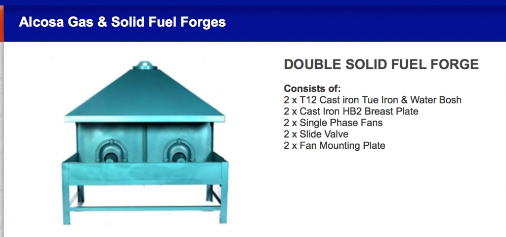
Is there any any reason you don't just build it like a standard double hearth? They seem to work fine with a single flue whether one or both fires are lit. You could always put a sheet / plate divider between the fires if you wanted to. The old ogee shaped cast iron hooded Allays and Onions hearths were a much sought after prize over here. My Supreme Master Blacksmith neighbour Mike Roberts managed to find one and used it for 40 years with no problems. Many of you in the USA will know Mike for his brass forging expertise and his regular attendance at the ABANA conferences over the years...more recently his workshop/masterclass at the Memphis museum. This is the modern fabricated equivalent available from Vaughans. Alan
-
As discussed by others above, no-one wants you not to follow your dreams. But maybe do a reality check or two first. Just by way of empirical research...take a woodworkers handsaw and tape off, or mark the length to leave the number of teeth you have shown on your dream design (around 175mm-ish?) and try sawing the sort of wood you envisage cutting with your knife, restricting your stroke to the 175mm. I think you will find it will only be good for tiny branches, have a very short stroke, an unergonomic handle angle, and at a minimum of 5mm thick before any 'set', will be removing a very wide saw kerf, about 3 or 4 times the width of a woodworkers saw. Very inefficient. Having said that I have used the wood saw on my Victorinox multi tool to very good effect, even if it was awkward it was much better than nothing. But that has a thin hollow ground blade with flush cutting teeth which are also not exposed when not in use, and I was not trying to cut down a tree. Coupled with the built in weakness of crack-starting points for when you are chopping your shelter trees down, the saw knife combination is maybe not such a good idea. However, enjoy the journey and experiment... Charles' suggestion of starting out with a length of band saw blade which would give you a useable saw with little effort and grinding the blade profile on the other edge would seem an excellent way of testing your concept with minimal cost and time. Perhaps you could buy a cheap machete and modify that to start with? Just lop the end off to see if the size and weight is how you imagine it will feel and adjust that until you have the balance you want. Experiment with the handle shape etc. Alan
-
 It is only dipped momentarily so you remove very little heat from the workpiece. The small thermal mass of the ismuth relative to the workpiece means it chills (and reheats) very rapidly Speed is key. If you hold the soon-to-be cut off piece in your tongs when you pop it in the water you lose no time and do not allow the ismuth to reheat. If I am cutting a waste piece off I often just plunge in and then bang the bar on the edge of the water tub to knock it off...you have to watch that though because some times it manages to come off on the rebound and come visit! You may realise how I know that. Alan
 -
When using a hot cut I find it advantageous to plunge the workpiece into the water bucket for a second or two, after hitting it down onto the hot cut, the only bit that is chilled is the ismuth left from the part cut, and because it is cold the end will break off clean rather than having to bend and twist with your tongs. You obviously have to be a bit quick or the residual heat will travel back into the ismuth almost as quickly. With this method you do not need to risk going so close to the hot set with the hammer face. A straight edged hot set will produce a parallel strip/hinge/ismuth which will break cleaner and more readily than the hinge left by a curved edge hot set. The more ragged edge left by the curved tool will require a few more blows to clean up and consolidate. But probably not enough difference between them in the real world to worry anyone. Alan
-
Small smithy ventilation
Alan Evans replied to harry robinette's topic in Building, Designing a Shop
Had a visitor so I posted above before I had finished....but meant to say that the Glass studio at Farnham had two or three glory holes under a canopy with a chimney...I do not know whether it was natural or assisted. Alan -
Small smithy ventilation
Alan Evans replied to harry robinette's topic in Building, Designing a Shop
I have a door on a wire rope and pulleys to a boat trailer winch on the big furnace. It even has provision for a secondary horizontal sliding door suspended below. The secondary door was used for a few years but the projects for the last decade or so have been better served by a line of firebricks across the bed just inside the door which leave an appropriate gap for the workpiece. I tend to double up the shorter lengths so I can use one piece as a handle while I forge the other so I have a water tank below and some sacking which I wrap around the piece and keep pouring water over the sacking which drains back down into the tank. The reason for that description is that a friend working up in Birmingham, Ian Moran once told me of a place he worked which used an air curtain to keep the handle pieces cool. It was a length of scaffold pipe set with a row of air blast holes pointing up which took some of the air from the burner supply. He said it was very effective. Alan Dawson used my big furnace and burner design as the basis for his, and he improved on it by enclosing it in a steel jacket which had a chimney out to atmosphere. Can't quite remember whether it had a cowl overhanging the door to catch any heat from there. My burner design is an amalgam of one Tom Joyce from Santa Fe sent me and the college notes borrowed from the glass studio technician at Farnham Art School. The glass studio glory holes were the basis for my first furnace used for heating 2" square aluminium lengths. I went onto heavier construction when I wanted to heat heavier metal. Alan -
Small smithy ventilation
Alan Evans replied to harry robinette's topic in Building, Designing a Shop
It is because you had posted your qualification earlier that I prefaced my contribution so that the OP could treat mine with the suspicion it deserved! My experience of the awful system that was installed at my college forge...metres of horizontal flue ducting, collecting from a number of hearths and in-flue extractor fans which seemed to fail frequently. Led me to to look for the simplest most naturally aspirated system. In-flue extractor fans seem to be in the worst place...amongst the concentration of any dust and corrosive fumes...for long term service. My first hearth, a standard Alcosa side blast in a 3 x 4 metre (9' x 12') wooden building initially used the Ø10" flue it came with. When I installed power hammers I converted the hearth to a bottom blast with a long air-slotted base plate which gave me a 600mm (2') heat to make efficient use of the power. The flue could not cope, so I made up a 300mm (12") square flue which doubled the area. At one time when I had neighbour difficulties and needed the door closed I was working with air-fed face shields from the compressor...horrendous. The new forge building was block built with 100mm (4") blown insulation and initially I thought would be large enough not to need assisted ventilation. But then I built a 1220mm (4') gas furnace which would not go under the hearth canopy. I rapidly installed an opening roof light and the positive pressure fan and we still opened the doors when we were not actually forging. We then found it was much better to cover the furnace with a sheet of steel for weather protection and leave it outside and carry the workpieces in to the hammer. Even with the big furnace outside, with large sections like 80mm and 100mm (3" and 4") the radiant heat coming off a 1220mm (4') length means the blast of fresh air blowing over us down the line of the hammers and presses is most welcome. Alan -
I have always known the little vices as hand vices. The pliers I was told were upholsterers pliers but I guess any trade working with fabric/leather and needing to tension and tack it...I found them to be the perfect tool for removing the plastic trim rivets in my old Discovery. The cutters seem to have such a wide range of angles. I wondered if some of the steeper ones were for cork bungs in wooden casks. But the shallow ones are too shallow even to be a countersink. Maybe a clue to ascertain how hard the material and how acute a cutting edge they have as to what they were designed to do. Maybe they are not even all from one set...just similar toothed wheels wired together? The pipe wrench / thread chaser tool does not seem to have enough difference end to end for different pipes...neither does the adjustable spanner come to that...curious. What shape do the spring tool (top right) jaws form when they are closed? Can you take a photo from the jaw end looking at the jaws? is it a lead seal crimping device? Bottom right I know as a tinsmiths/sheetmetalworker rolled joint setting punch, as Ian described. Middle right, can't see but is the broad end of the Z shaped piece a chisel? The bruising from the hammer blows makes me think of a glaziers putty removing knife. It is used like a miniature froe. BIGGUNDOCTOR's farriers tool sounds convincing. I thought the farriers I have watched twisted the excess nail bits of with their claw hammers and then filed them flush. Alan
-
Small smithy ventilation
Alan Evans replied to harry robinette's topic in Building, Designing a Shop
All very basic and unscientific I am afraid. I bought the largest (600mm / 24") Axial Plate fan available from MachineMart that had a variable speed controller. The difference in price between the largest and smallest (300mm / 12") at the time was from 100 pounds to 200 pounds. The extra 100 pounds I paid covered a lot of calculations. Probably about double that now twenty years later, but still cheap insurance and comfort. The blockwork buttress/chimney and sound baffled air inlet I had built probably cost four or five times the cost of the actual fan so I felt no need to skimp on power. I think it is capable of shifting the total volume of building every couple of minutes when its running flat out. It is rarely on much more than tick-over but good to be able to give it full blast when the smokey old diesel fork lift is around. Unless your building meets PassivHaus standards I understand the positive pressure will find its own way out...line of least resistance is the hearth chimney, an open sky light or an open door(s). The advantage of the skylight or chimney is that any sound is directed up rather than across the fence to your neighbours....provided you don't have a domed/reflecting cowl on the flue and the skylight opens to a vertical position. Alan -
Small smithy ventilation
Alan Evans replied to harry robinette's topic in Building, Designing a Shop
I am not a ventilation professional. I read that the Fire Brigade find it is quicker to use positive pressure ventilation to clear a building of smoke and fumes than to use the same size fan as an extractor. This is on the basis that every cubic metre of air moved by the fan is a cubic metre of fresh air into the building. Used as an extractor, the fan is moving mainly smoke to start with, but then every subsequent cubic metre is a mix of fresh air and smoke, so it is much less efficient. I also found that positive pressure ventilation has three other advantages for the forge. If you have a flue above your hearth, positive pressure assists the flow of smoke and fumes up the chimney. An extractor fan in the wall will have the opposite effect. It has the effect of blowing any sound back into the forge which may help reduce any noise problem for your neighbours...think of the way sound carries downwind rather than upwind... I set mine up so it blows fresh air directly onto us working on the hammer or presses. Alan -
I have done the same with one of mine when I first got it. But it is a bit like the horrid sound of a file being slid into a drawer full of other files. When my files were in a drawer I never made that sound. When I started having assistants in the forge I quite quickly made a file rack to prevent that noise. Having paid for and or restored them all, I am quite gentle on my tools and don't slam them around, so the vice bar rarely drops....And I only had a couple of blood blisters before I learned to keep my fingers out of the nipping point. Alan
-
Why are you concerned about the noise from the vice bar? You are about to make an unholy din whacking whatever you have put in there with a hammer! Alan
-
I have reversed a standard extractor fan to give me positive pressure ventilation in the forge, works very well. Especially helpful if you need to keep the sound in. Alan
-
You might be interested in a thread we had about scrolls and spirals a few months ago... http://www.iforgeiron.com/topic/28811-spirals-scrolls-and-growth-linesmy-understanding/?page=1 Alan
-
I was compiling a response when you posted, but mine then disappeared...grrr. I have started a new thread with a similar title (disappeared House Number Sign) and tried to report it to the mods to insert it here...but then the software would not forward the report to the mods....double grrr. Maybe this one won't arrive either... Alan p.s wow! it did and it brought the image I had been trying to post in also...now I am really confused
-
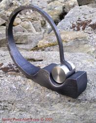
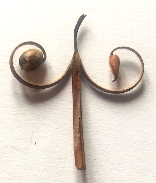
To prove my point...here is an illustration of a correct scroll! Lesley has just this hour returned from a visit to an "open garden" and her friend gave her this bit of plant for me as it was scroll-y. I thought it was too coincidental to be true! You can see that the spiral part is pretty regular in its gradual and consistent transition, but that the flower although it came off tangentially did not conform to classic form of the penny end scroll...obviously whoever designed the plant had not studied 18 century ironwork best-practice! Alan
-
I think there is no "correctly" with regard to form...you do whatever you want. My observations were because you mentioned they needed a bit of tweaking and I was tying to describe the classic form of penny end in case that may help you to visually analyse them. You may well wish to go even further from the "classic" form, your choice! The most powerful scrolls I have seen are almost barbaric and certainly not smooth flowing 18 century classic form. There are loads of images if you google penny end scroll, even some you tube videos if you want to go down the conventional route. You will see what I meant by gradually opening space. The gap between the elements starts as a tangent to the snub/penny and gradually moves away from it further and further. On your ones the gap starts to open up but then it goes tight again. Alan
-
What an intriguing find. Did you manage to track down any history of it? Former use of your little spread? Bank robber gang hideout and dumping ground? Locksmith lived here and brought work home? Alan
-
The classic penny end scrolls have a gradually opening space between the coils. A triangular space curled up. In the bottom photo, the scroll which would be above the number 4 when the sign is upright is the closest to that. Regarding the mounting of the numbers, ask yourself lots of questions....for instance... What is the behind the final sign mounting position? Plain background / fussy distracting detail / lots of space? Is it Front lit or Back lit? Would the numbers read more clearly if they were mounted on a sheet of steel, copper, glass or wood which was enclosed by the frame. Will they be more effective kissing the frame or visually floating away from it? Work out a fixing system which conforms to and works with all your answers. We have both mentioned copper. You are aware of bi metallic corrosion and how you avoid that being an issue when you mix metals for exterior use? Alan
-
Yes really. I think it is one of those combination tool things...does a lot of things badly (okay-ish) rather than one thing well. Like Thomas says above, I make and use dedicated swages which go under the press or power hammer. The bolster and drift system I have constructed have sliding jaws so they support the the metal immediately adjacent to the drift as you open up a hole...I hadn't used fixed bolsters for punching/drifting for decades before I acquired the swage block, so the odd shaped holes were not much use. So it has sat unused and unloved on the floor ever since I acquired it. The other unused tool investment I made in the early days was a beautiful nibbler. It would cut 3mm (1/8") mild steel plate with a minimum radius of 50mm (2") and had a straight line cutter for 3/16" mild or 1/8" SS. Much more than I could afford, but Michael along the road had one and his mainstay at the time was making canopies to go over open fires...he made thousands of them. I ended up making three in my forty odd years of practice. The nibbler has laid in the drawer snoring loudly ever since 1979. Alan
