Alan Evans
Members
-
Joined
-
Last visited
Everything posted by Alan Evans
-
The Gloucester Waterways Museum has a Bradley(?) helve hammer that they restored to full working order...well I say full. The museum has this really enlightened policy of allowing starting-out blacksmiths to have the use of the facilities rent free, plus free coal/coke provided that they did not sneer at, or scare the visitors. The restriction was that the forge was fixed in the 1890's so they were not allowed any technology more recent than that...the maintenance workshop across the yard had a mig, saw and gas bottles which they could use after public hours or out of sight. A number of good smiths started out there. Michael (Myloh67 on IFI) and Gunvor were there for a year or three. One of my assistants, Matthew Fedden, was the first to take it on within a few months of starting up. When I went down to have a look around the only bad thing was that they had some new pallets made for the restored Bradley and when I pointed out that they needed to be dressed before they could be used, the museum director would not allow Matthew to "grind up our new tools"! When we went to some length to explain why sharp edges were a disaster he eventually conceded. Myloh67 may have some insights into working and maintaining such a hammer try sending him a PM. Alan
-
I was trying to understand whether the 90˚ angle between the shaft axis of the hexagon socket was the sole criteria. Does your socket making process ensure that the hex socket is centred in the boss...ie is the socket concentric with the external surface? Irrespective of the concentricity, if it the axis of the socket rather than its external surfaces that matter...and if the rotational alignment of the hexagon with the shaft after bending would be an advantage, then the bending jig could be based on a male hexagon form to locate and align the rotation of the socket as well as the angle between the socket and the shaft. Alan
-
The ones I have seen are cast. They have a 1"-ish deep recess to locate the block when laid horizontal. So in plan view they are block size plus an 1"-ish rim and a bit of clearance all round. The block sits in the recess on square corner blocks which leave a cross shaped space in between.The width of the cross shape (two slots) is clearance on the thickness of the swage block so it can be stood on edge in the stand. There is a shelf at a lower level than the corner blocks to support the lower edge of the block when stood on edge in the slot. I have seen one with just a single slot rather than a cross. Alan p.s. A google image search for "swage block stand" brings up a load similar to JHCC's image links. The Alldays and Onions ones were common over here...nearly every school had one. p.p.s. Forgot to add that mine has just sat on the floor ever since I had it. After thirty odd years in the business somebody offered one to me, and I thought oooh I am a blacksmith, every blacksmith should have a swage block. It is the singular most useless (well strictly speaking most unused) tool I have ever purchased. It has just sat on the floor just inside the door for the last twenty years. I used it once to form a robust trestle, not even very good for doing that! Alan
-
Once the aluminium has taken the form of the file teeth any abrasive action the other way around would be maintaining (and sharpening) the file tooth profile. The file card wires are dragging across the tooth edge and likely dulling it rather than acting like a butchers steel. The profiled aluminium is more efficient at removing the pins, only one pass is required, so less contact with the tooth edges than the few hundred wires rubbing across per session. that's my story anyway. Copper, brass, wood or some hard plastics would work also. Aluminium is what I had in a handy section when I needed it, so just used it ever since. Try it once and you will only pick up a file card to chuck it in the bin! Alan
-
I have used Wax (don't use silicone if you are going to be painting or lacquering the piece afterwards) to help with minimising pinning when filing soft stuff like aluminium. Though French chalk/soapstone seems to work well for me for most other materials. I have never used file cards. I found early on that a bit of aluminium flat or strip of sheet pushed across the file in line with the teeth...held like a wood chisel...was more effective at removing the pins. After a few passes the working edge of the aluminium conforms to the profile of the teeth and lifts out the pins cleanly. I think the aluminium pin remover has an advantage in that it is not burnishing and dulling the file teeth whilst cleaning it. The card wires are fairly hard spring steel, piano wire I presume. I never liked the idea of brushing hard across hard. I have used mild steel instead of aluminium in the same way, just takes a bit longer to conform to the teeth profile. My most used and favourite file is a Nicholson 8" flat no 6 cut. They were new old stock in the cheap bin at Suttons the jewellers supply store in the jewellery quarter in Birmingham. I bought one for novelty never having seen such a large fine cut file. You can hardly see the teeth. The following week I went back and bought the remaining ones. That was in 1976 -ish. I still have some, unused, waxed and wrapped in greaseproof paper in the drawer. Fantastic for non ferrous and silverwork when I was doing that full time. Alan
-
Alan Knight the smith I worked and trained with, spent his whole life working in the 18 Century / baroque idiom, so smaller sections and elements forged to shape and then fire welded together. He used a lot of wrought iron. His main forging hammers were standard 1 1/2 lb engineers ball pein hammers with long handles. One was flat (crowned) and the other was a full faced hammer. He did use leafing hammers and other specialist shapes for specialist processes of course. He frequently forged all day well into is seventies. The sections were light and his energy was directed into putting the hammer down fast and in the right place rather than lifting it. He used the profiles of the anvil to direct the flow of metal. He was rare in that he always forged waterleaves from flat bar, instead of the current practice of forming them from heavy sheet, spreading them out along the axis of the bick with the full faced hammer which I think gives them much more articulation. With the right weight of hammer for the project the rebound does most of the lifting. Alan
-
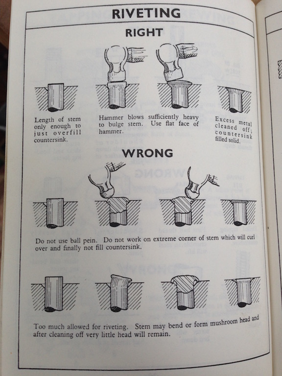
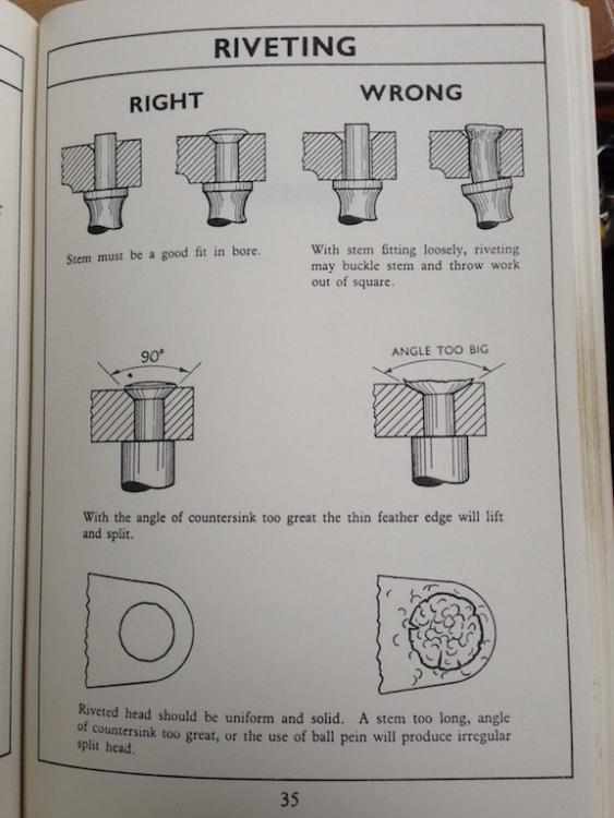
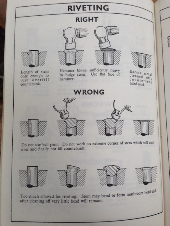
Found the photos of my split bolster variation...and in the same folder was a useful guide to riveting, especially pointing out the danger of using a ball pein instead of a flat hammer to initiate the process which may be of interest to some. Alan
-
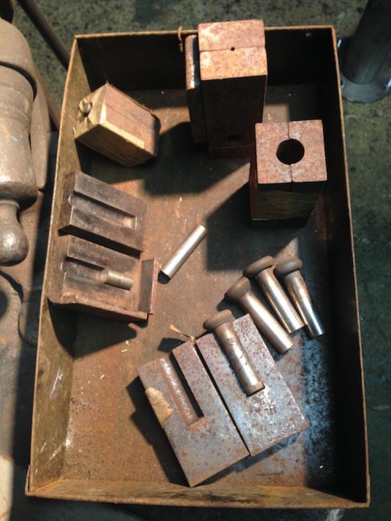
Split bolster. Two bits of flat clamped or tacked together. Drill down the centre join of the flats the diameter of your rivet and flat bottom the hole at the depth you require. Clamp in leg vice with rivet material in place but raised a few millimetres out. Heat with gas torch, initially drive down with a heavy flat faced hammer, to upset and establish shoulders, and then form with the rivet snap you show. Flat size for a Ø1/2" , use say 2"x1" or even 11/2" X 3/4" or 1"x1/2" would do as you only have a few to make. The heavier the section the better the heat sink. Smaller section flat just quench more often. I usually use 2:1 profile so I can tack weld them together (which forms a square) so I can hold and drill them in the self-centring four jaw chuck of the lathe. Before I had such things, just clamping and drilling accurately with a hand drill worked fine...the drill bit tends to follow the joint. You can flat bottom the hole by grinding the same size drill flat ended. You might get away by using a short section of Ø1/2" in the bottom of the hole. I often drill the bolster deeper and then use different size filler pieces to set the lengths for different rivets. But I always flat bottom the hole even when using a filler. If I am making hand made rivets I do not try and emulate machine made round heads. I either leave them as a thick pan head from the flat faced hammer, or I make them five clout with a short polished punch (effectively a mini flatter). It depends what the project calls for. That way you can celebrate any wobble! Alan ps I think I have posted some photographs of my split bolsters on here before, I do not know if they are still available, try a search.
-
Do you wish to align the facets of the hexagon socket with the axis of the bar in the same position each time or happy for it to be random? Can you use the external surface of the socket in a 90˚ bending jig or would it be best to be able to align the hexagon flats or corners? If the drilling jig supported the socket on its shoulder and a drill guide was used inside, a slight variation in the bend angle would not affect the hole direction. It would still be in line with the axis of the socket. Alan
-
The narrow anvils shown above appear to have the slight curve along their length that I was referring to in my cross pein. If you just transpose those forms...the flat hammer and the crowned narrow anvil...to a flat anvil and a crowned pein You will be able to see exactly where the hammer blows are falling and make the micro adjustments necessary to pull out just the area you need. The advantage is being able to see what the tool is doing rather than those tell tale bruises being obscured underneath. You should get better instant feed back that way. But if I am misreading the illustrations and the narrow anvils are straight, it is the crowned face of the flat hammer which is giving the "soft ended" effect required, which is the other issue. You want the narrow radius across the pein to act as a fuller and move the metal radically perpendicular to its axis. You want the crown along its length to make it move more in the middle with less movement at either end. So that as you move along the length of the blade subsequent blows blend together. Without the crown / ellipsoid ended profile, the metal moves equally along the entire length of the pein and leaves a sharp transition at the end. The transition will never correct with subsequent blows and always leaves a dimple in the scythe edge. Worse you are putting excessive shear forces into the metal at the end points with every blow. I will do a sketch or two if you can't make sense of what I have written.... What a fantastic gift with the coal. Nice when favours given come back. What goes around comes around and all that. I had a friend who alway said you should pass on a favour rather than just returning it...nice way of getting along with people! Alan
-
Your first images did not show that it was a socket, you knew it but I did not, which is why I described it as the larger diameter section! If you are induction heating and then bending by hand you need to align whatever you are using to hold the socket. As far as I can see from your later photos it is the socket that is off line not just the through hole. It looks like you have located the socket on a hexagon and then pulled the bar over to form the bend, but then twisted it clockwise so it is a compound bend and the socket head is out of line. Or you have pulled it down diagonally. For the drilling, if it is important for the function of the tool for the hole to be in the centre line of the socket then I would make a drill guide with a hexagonal exterior to fit into the socket and drill through that. Provided you have pulled the bar down in a straight line it will come through the centre of the bend. My Tee weld suggestion was based on the external appearance before learning that it was a socket and needed the through hole. As far as the wasting/waisting of the outside of the bend goes, I referred to a larger radius not a different angle, but I can see that may not be appropriate now. I have not played with induction...but are you able to create a coil which would heat a longer length on one side of the bar, and then use the longer heat length on the inside of the bend in order that the metal thickens there rather than stretches on the outside of the bend? Easy with a gas torch. Alan So is your difficulty not the stretching/thinning of the metal on the out side of the bend as I supposed, but rather being able to achieve 90˚ accurately? Or is it the offset of the socket to the bar? Alan
-
A longer heat to spread the area of stretch? A larger radius bend? Heat on the inside of the bend to upset the metal there? If you are welding the larger diameter section on, why not keep the bar straight and extend the larger section to it and make a tee weld? How are you heating it, by induction or flame? Alan
-
If you are in the USA you presumably know about Peter Vido.... http://scytheconnection.com/about-us/ Alan
-
If you have problems with hammer control thescytheshop.co.uk sell a jig, presumably they are available wherever you are.... I found a compound curved pein was effective on a polished block/anvil. Just enough curve along its axis to prevent the ends from leaving bruises. I ground it until it left a cigar shaped / long ellipse mark. It works well for pulling out cracks and snags as well as thinning the edge. Alan Peening Jig The jig is an alternative to the hammer and anvil which ensures that you hammer out the blade to a prescribed thickness. It requires less skill than freehand peening, and so a novice is much less likely to damage their blade — but on its own the jig will not normally achieve as good a result as accomplished freehand peening. The jig is also not as effective as a hammer and anvil for repairing cracks and nicks in the blade. On the other hand it works well on the tight curve of a sickle. The jig consists of a cylindrical polished metal drum, about the size of a small pot of face cream, with a spike coming out from the underneath to fix it in wood, and a machined metal column projecting upwards from the centre of the top circular surface. The blade is held the normal way up flat on the anvil with its edge touching the base of the column. A hollow cylindrical cap is placed over the column. This is accurately machined so that when tapped with a carpenter's hammer, it will compress the edge of the blade in the correct place. The blade is moved along, a millimetre at a time, as you tap. A second cap will compress the extreme edge of the blade even finer. There is a lot to be said for peening initially with the jig, to get the basic profile right in safety, and then finishing off with hammer and anvil to get a keen finish.
-
-
Hot and cold short I have always associated with cracking (cold) crumbling (hot). Delaminating is another thing altogether and is invariably (IME) from working wrought iron too cold. It is why you should always take it to welding heat and dap the ends together before doing anything like tapering or spreading or upsetting. I was told that Hot Short in wrought iron is when a fault or inclusion in one of the strands/fibres causes excess strain and failure to be passed to the adjacent strands across the bar in subsequent working until it falls apart. The inclusion was said to be sulphur. Alan
-
Too late to edit... Jenolite is a Phosphoric acid based rust converter rather than de-ruster. Alan
-
The picking paste available in the UK is definitely not Phosphoric acid as in Coca Cola. It is a blend of Nitric and Hydrofluoric and is very nasty. I have some and have used it, but now I know what it is, I wish I hadn't! Quote from Health and Safety Executive website:- "Pickling pastes typically contain 20% nitric acid and 5% hydrofluoric acid by weight, although this can vary. Hydrofluoric acid is a highly toxic, reactive chemical. Skin contact with diluted solutions can cause very serious and extremely painful burns. The extent of these burns can readily be missed at the initial stage, as it can take up to 24 hours after contact before the pain is felt. The acid is also capable of destroying flesh long after initial efforts have been made to wash it from the skin. Very small quantities of diluted hydrofluoric acid can cause irreparable damage to the eye." full text here... http://www.hse.gov.uk/welding/post-weld-cleaning.htm avoid avoid avoid In the UK there is a de-ruster based on phosphoric acid with the brand name Jenolite which is available through the motor factors, car maintenance supplies places. Alan
-
We used to live on goats milk junket every evening for pudding. Any junket left over was hung up in a muslin square and dripped, the cottage cheese on top of bread and jam was delicious. Almost as good as a cream tea. Mum tried butter and cheese but she found they were too labour intensive for the return. Junket and cottage cheese were pretty easy. Alan
-
A toe jack could be quite a useful tool in such circumstances. But a wedge or lever and a thump should do fine! Alan
-
The only bit that may be heat treated is the jaw face. Warming up the side plates of the hinges will crack any rust bond. But I would be inclined to just get brutal with it! Levers are your friend. A tyre lever or jemmy or folding wedges between the jaws to open it and bit of plywood on the ground to drop the moving jaw on to close it, allowing the weight of the whole to do the work.. Copper faced Thor hammer/mallets are most useful for such purposes and only cost a few pounds. Don't forget leg vices were designed for, and made from materials that would to come to no harm from having things in the jaws hit by hammers. Good looking vice, hardly any wear on the thread... Alan
-
Definitely an area to explore in the another piece. Alan
-
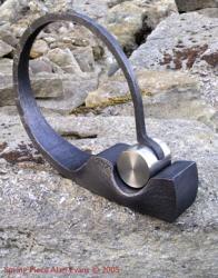
The armature is the profile and rings prior to cladding. Images 9,10 and 11 Alan
-
Good fun. I trust you happened to notice how visually powerful and effective your armature is. You should definitely log that away for the future. Alan
-
I am surprised at all the negativity. Looks a wonderful old thing to me. It certainly does not owe the blacksmithing profession anything. And still has a lot more to give, even just as is. I guarantee you will be able to create more forms with it just as it is than you could do with an undressed flat topped sharp edged brand-new anvil straight from your favourite supplier. The wear pattern with no damage to the bick makes me think of a life of pointing chisels and drill bits in a mine or quarry. But whatever the process, it was in use complete with its sway back probably right up until the hard facing finally gave up...Obviously good quality weld in that it had done pretty well to conform to that amount of sway up until then. Looks like it was chucked outside and got a bit buried in leaf mulch or whatever to cause the deep pitted surface on the sides. My father always looked for well worn tools, reasoning that somebody had found it was a good tool and liked using it enough to put some wear on it. You never know but that bit in the middle might make a perfect cutting or chiselling soft surface for a particular project. If you don't find a use for it as is, that is the time to think about restoration. In that case I would be inclined to restore it back to a hard faced sway back and not try and make it a flat top. Honourable tool, enjoy it for what it is. Alan