

D.Rotblatt
-
Posts
335 -
Joined
-
Last visited
Content Type
Profiles
Forums
Articles
Gallery
Downloads
Events
Everything posted by D.Rotblatt
-

3D printed plastic burner experiments (photo heavy)
D.Rotblatt replied to Another FrankenBurner's topic in Gas Forges
Nah, it was proof of concept. I was changing tips over and over, and the tape just got crumpled. It started as a straight tube, and I imagine it will work better if it's not a crumpled mess. Even if it did increase the size, that would be a solution... I'm going to try this one next: Walls on the side 1" high with a choke that has either 0, 2, or 3 fins on it. They are all printing up now. Same trumpet shape as the cast burner. We'll see how that works. All of it is castable in sand (although fins are harder, but it's small, I should be able to unscrew it from the sand....). DanR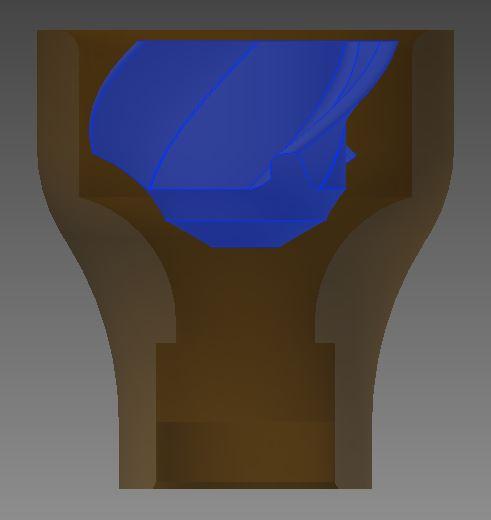
-
3D printed plastic burner experiments (photo heavy)
D.Rotblatt replied to Another FrankenBurner's topic in Gas Forges
TINKERING UPDATE: Great success today! I tried two ideas we had talked about, and both helped. I got the bronze burner up to 2290F. The Reil went up to 2230F. The cast burner also ran well with a .046 mig tip. Here's what I did: I simply ran some tape around the bronze burner to make a lip. One width of tape didn't do much, but two did (standard sized blue tape). It was rough, but the sound changed and the flame became more lean. I had a small choke plate, and i put it on. Mikey, the sweet spot for this was with the choke plate about 1/2-3/4" back from fully closed. If I moved it back or forward it didn't seem to change the quality of the flame much, but the temperature went down. Might be a mixing thing. It occurs to me that if I am putting a tube on the back of the burner, I can put fins on the choke plate that extent to the edge of the tube (i.e. the choke plate is about 1" diameter, while the tube is 2" diameter). I also tried shortening the MIg top to about .3". This was also very effective. With a long .046 mig tip, I got a very rich flame. With the shorter tip the flame became much hotter and leaner. Off to bed! Was a good day. Now to play with some new designs that add a 'Lip' before the reducer. Several ideas come to mind.... DanR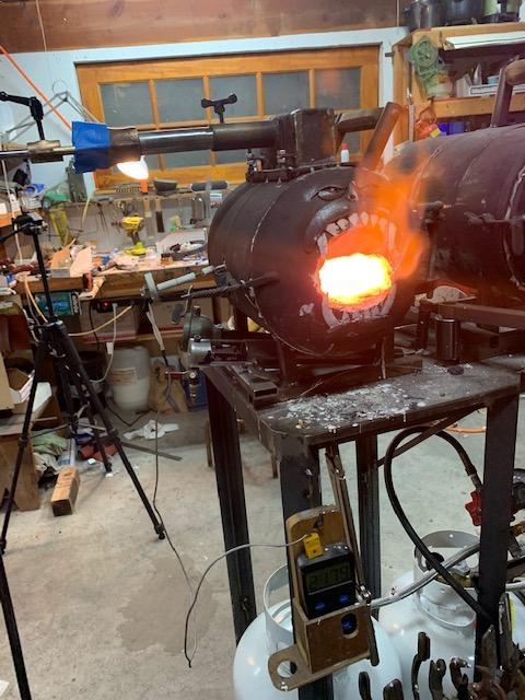
-
3D printed plastic burner experiments (photo heavy)
D.Rotblatt replied to Another FrankenBurner's topic in Gas Forges
That looks right from the first image of the failed cast - I've had the exact same results with failed casts on bronze that's too thin or the metal too cool. The differential in the temperature from the molten metal to the mold material is 2500 degrees - the heat gets pulled out of it fast. With bronze pouring temp is a couple hundred degrees over melting temp too, I allow 5 minutes time to heat after melting (unless I'm impatient...). You might need more with iron because it's pouring temp is closer to the temp of the forge. Seems it's the opposite of aluminum, which has problems if it gets too hot. With Bronze it doesn't matter if its a little extra hot, you'll have to see with iron. Head pressure will also push the iron into the mold, but your pouring sprue looks plenty large and high, so I don't think that's the problem. With good sand casts you can see finger prints - it's gets surprisingly fine detail as long as the sand can release well. I'm impressed that you're pouring iron! Never did that, but you are making it look easy. I also like your use of tongue and groove to make the box alignment - good thinking! DanR -
3D printed plastic burner experiments (photo heavy)
D.Rotblatt replied to Another FrankenBurner's topic in Gas Forges
Wow....too much info at once! My brain is exploding!!! Yes it is. And you have much to offer. Love to hear stories about Ron Reil and you guys developing the early DIY burners. If I get you right, the hotter flame may be leaner and less efficient (less BTU's) but heat the forge hotter. One thing I did notice was that the dragons breath on the Riel burner is much larger for the same pressure. I tried to tune the burners to be the same mixture (neutral for this test), so the flame should be the same temperature. The difference between seat of the pants tinkering and application of science with the backing of a multi-million dollar company.... Thanks for the references. I'll have to read them again. I don't know if the gas is actually changing direction on the Reil burner. It's a hole in the center of a 1/8" capped tube rather then a bent tube. Imagine the gas backing up in a .25 x 3" chamber under pressure (the capped tube), in the side is a hole. The static gas is pushed straight out the hole rather then turning a corner. Either way, it seems there might be a large difference between the channel and sharp edge type of orifice. I'll try shortening the Mig tip, and maybe I'll fabricate a sharp edge tip as well. I'm also thinking about the lip on the reducer you mentioned. A little tape and cardboard could add that to my bronze burner. I'll give that a try as well. BURNER TEST UPDATE: I did try the yellow A.Frankenburner type of injector. The flame was similar to the one on my burner, but visibly smaller. Reacted the same when connected to the ribbon burner. Obviously restriction of the intake due to the fins. I'd take a break on this and let it stew a bit, but with the heat out here (around 100F) I'm not doing any forging. DanR -
3D printed plastic burner experiments (photo heavy)
D.Rotblatt replied to Another FrankenBurner's topic in Gas Forges
Yup! Works for me! -
3D printed plastic burner experiments (photo heavy)
D.Rotblatt replied to Another FrankenBurner's topic in Gas Forges
Your thinking seems sound to me - and your guess is always an educated one I respect! This choke also is sweeter between about 3/4 to 1" out also. Further and I can smell a touch of propane around the burner, it seems to me the jet of gas is widening so it's not all focused into the tube. Still thinking and pondering the results... DanR -
3D printed plastic burner experiments (photo heavy)
D.Rotblatt replied to Another FrankenBurner's topic in Gas Forges
You're right about the casting. I could make them much wider with ease. It seems 3 openings trump 2, but I'm sure two would make some difference. In my experiments I did find that it took a lot to get that swirl though. It would be worth a try, easy to do one on the printer. It should, it's a unabashed copy, and thank you!!! There are so many variables here it is mind boggling. I don't even know if my burner is worse then the Reil. Both have .036 openings, but the Reil's is about 3/32 deep (thickness of the brass 1/8" pipe) while the other is a mig tip. The mig tip may restrict the flow due to it's length, and thus the burner may be more efficient, but need to be turned up to a higher pressure. Certainly the dragons breath out of the forge was much greater with the Reil. I may have to do a several hour run where I am measuring the gas consumed the same temperature rather then pressure, that's a real test of efficiency. Most of the DIY burner crowd is going on non-scientific observation. One person says something is fantastic because it worked for them, so others try it, it works and many people copy it. But we don't really have a back to back comparison. I've always had great experience with Reil burners, I tried some sidearms years ago and they just didn't work for me, much poorer heat then my Reil. Wayne Coe used crayons in his first ribbon burner, so everybody followed. I tried 1/8" sprue wax, and it's far superior stability at low pressures to the one I used crayons in (even that is an apples and oranges since my 1/8" is NA and the other is a gun). Even my Mikey burners don't seem too much different then the Reil when I stick them in my forge, though they work much better outside the forge. Once more, it may be a pressure/efficiency thing or the Reil may work really well with back pressure. You are also right that I am using this as an injector for a ribbon burner which is a different application then a straight burner. Both my forges are set up for ribbon burners right now, though my small one is easily convertible (3 nuts) - I just haven't made the regular burner assembly since my ribbon burner works so well. I just realized I do have a furnace set up for a regular burner...I'll try them in that today and see if there is a difference. It is! But it's like the hydra, cut off one head, and it grows two more. At least it's a fun cuddly hydra to play with! I'm loving the 3D printer for making castings. I've been thinking about it for years, but I've had no practical application. Models of knife/sword guards and pommels are just easier/quicker to do freehand then on the CAD/3D printer. And since the model is reusable in sand casting there is no need for multiples. Cheers! DanR -
3D printed plastic burner experiments (photo heavy)
D.Rotblatt replied to Another FrankenBurner's topic in Gas Forges
Ive tried that, both shallow and tall ones. Doesn't seem to make any difference. Most of the air is pulled in around the nozzle or choke in my case. Thanks Mikey. I'm definitely going to try some mods - thought I had a good one, but should have tested inside the forge. I don't know why a flat choke disc would work better then a conical. I'd love to know what your thinking is on that. It seems that the conical choke would focus the stream of air better. Yes they do. I'm starting to go a little wonky trying to figure out negative/positive/negative spaces. I found a command on my CAD program tonight that allows me to create negative spaces of any object I make. You just merge two objects and subtract one. Now I have to figure out how to make a multiple piece core (kind of like one of those wood chinese puzzles) in case I want to cast one with fins. The Riel burner has a 1.75 reducer, and is actually 1.75 ID inside. The OD of my burner is 2.25 (remember, I'm working with a 3/4" burner tube not 1/2"), but since it is a trumpet shape rather then a bowl, there is no real ID. The trumpet is .75" deep tapering to the width of the ID of the pipe (.84 I think, but if I rub my finger in there there is no lip). I believe the radius on the trumpet is 1.75". I was thinking the same thing today when I pulled apart the Reil burner to see what the jet size actually was. It's certainly food for thought. I just copied your v40 burner as best I could from the pics (80 degree fin, etc - looking at it I might have made the ring too close to the trumpet...we'll see tomorrow). Same trumpet as the bronze burner, so the variable is the fins. I left space in the center for a smaller choke that will plug that hole in the disc and be able to be moved in and out like the bronze one. We'll see if it pulls more air. And for those physics folks, and an interesting factoid (and before one chimes in) - I was taught back in college that there is no 'pulling' in physics only pushing. The jet is creating a low pressure area, and the pressure of the air around it is pushed into that area. DanR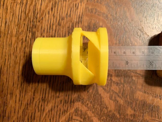
-
3D printed plastic burner experiments (photo heavy)
D.Rotblatt replied to Another FrankenBurner's topic in Gas Forges
It's a sad day for tinkerers here at the Old Canyon Forge. I tested my new burner against a Reil Burner with Bourdeaux modification. I ran them through my modified ribbon burner at 5 lbs pressure (I have a quick release on my propane, so it was the exact same pressure), and ran them until the temperature stabilized. The thermocouple was not moved either. i.e. the only variable was the burner and the jet on the burner. I tweeked the mixture on the bronze burner until I got the highest temperature. The Reil burner has a .036 hole drilled in the pipe. I tried the Bronze cast burner with .036 and .039 (and others, but they came out lower temps). both the .036 and .039 came were the same temp. Reil Burner: 2198 F Bronze Burner: 2130 F The Reil burner is much louder then the new burner, sounds like it is sucking more air or the gas is exiting much faster. It is possible that the .036 hole in the pipe allows more gas to flow then the longer mig tip, thus my burner could be more efficient and have to be turned up a few pounds pressure to get the same result. The only way to tell now is to run them at the same temperature for a time and weigh the gas tanks. Which sounds like a pain. Especially in 100 degree weather.... The other variable is that this burner may not work well with the ribbon burner nozzle. It may need a different number of holes since it seems more powerful outside the forge. I made the ribbon burner head with the Reil burner, so it is "tuned" to it. Well, I'm trying some finned samples as Mikey suggested. Took a careful gander at Frankenburners v40 and made some mods to allow for an internal choke. Not sure if its castable though. Sigh, back to the drawing board.... DanR -
3D printed plastic burner experiments (photo heavy)
D.Rotblatt replied to Another FrankenBurner's topic in Gas Forges
I tried some with fins, (copied what I could see of Frankenburner's) but found little difference in the flame. The flame showed it was swirling, but it wasn't more powerful then the same without fins. Now, I might not have got it right, since it seems that Frankenburner is getting really good results. Tried a few with fins around the nozzle but it did not promote the swirl. Seems the fins have to go around the edge of the intake vortex. It also prevented this easy way of choking, though there are many ways to choke. The main difference in my experiments that I found was; first, simply the size of the orifice to the burner tube and, second, the shape of the intake orifice (mainly to stability). I was trying some that necked in and then opened up (what I called the 'Wasp' shape), but they restricted the size of the orifice and mainly just reduced the flame size (and jet size). I also tried an intake that was shaped like a plumbing reducer (but without the threads, etc) vs. one with flat sides (just a conical intake) vs. one with convex sides (like I am using). The plumbing reducer shaped intake (I'll call that concave sides) was just less stable at low pressures but produced a good flame, while the closer i got to convex sides decreased the pressure that a induced a stable flame. I don't know how a swirling inducer (fins) would induce more air into the mix unless it's decreasing turbulence in some way. I do see how that would mix the gas/air an allow for a shorter burner tube and possibly a more stable flame. I seem to be getting really good mixing with this. It's also very very stable. For example, without the choke on, I can move the jet from 1" inside the tube to 1.5" outside and the only difference in the flame is that it induces more air the further out I put the jet. Not to say I won't try a few more with fins...if only to make sure it's working. The problem with fins is that it makes it a really hard cast, since I'm doing a sand cast. Not impossible, but really hard. I think I'd have to make a multi part core. 3D printing makes this much more doable. Actually...it sounds like a nice casting challenge... First I'll try a temperature test comparing this to the Reil Burner (an old gold standard). DanR -
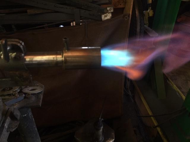
3D printed plastic burner experiments (photo heavy)
D.Rotblatt replied to Another FrankenBurner's topic in Gas Forges
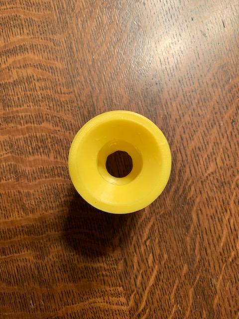
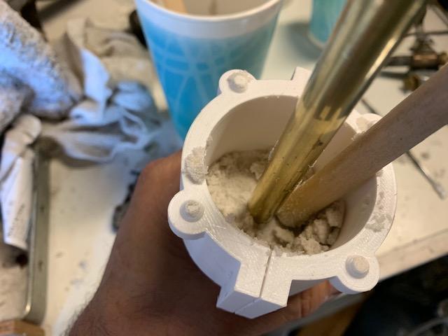
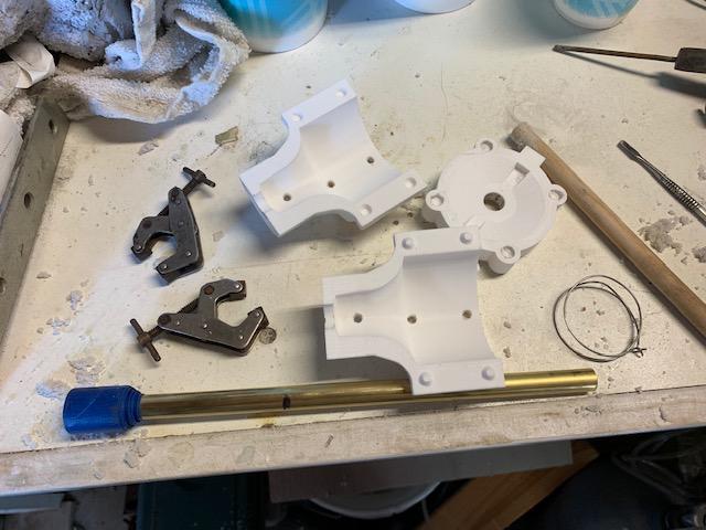
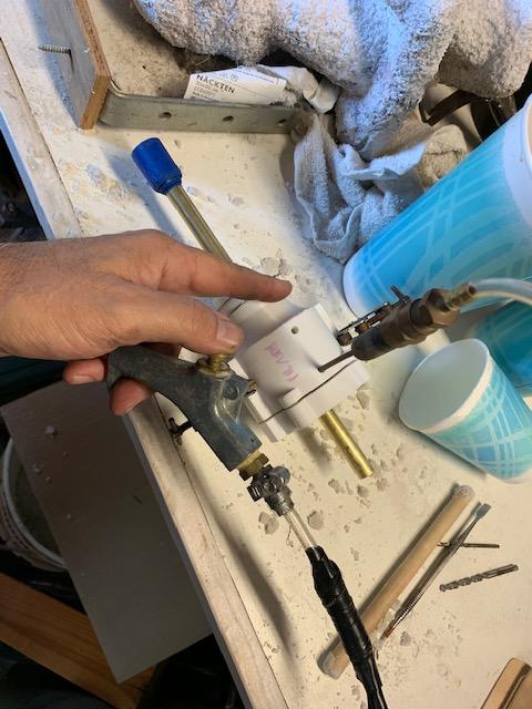
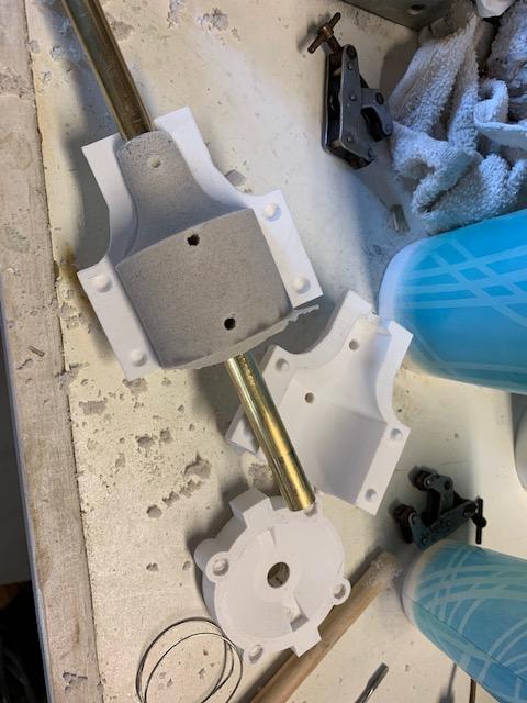
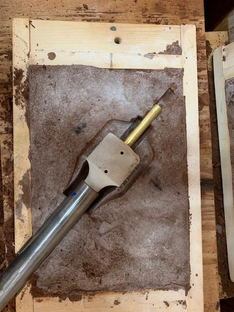
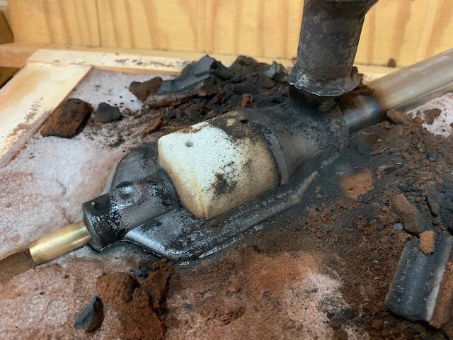
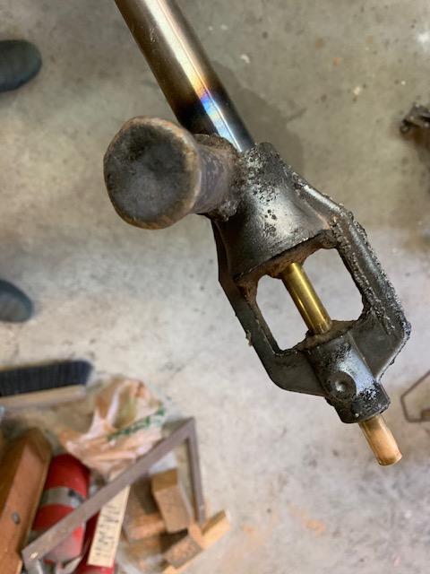
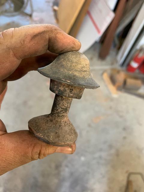
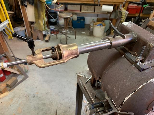
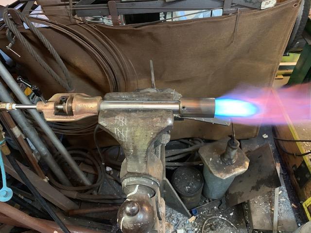
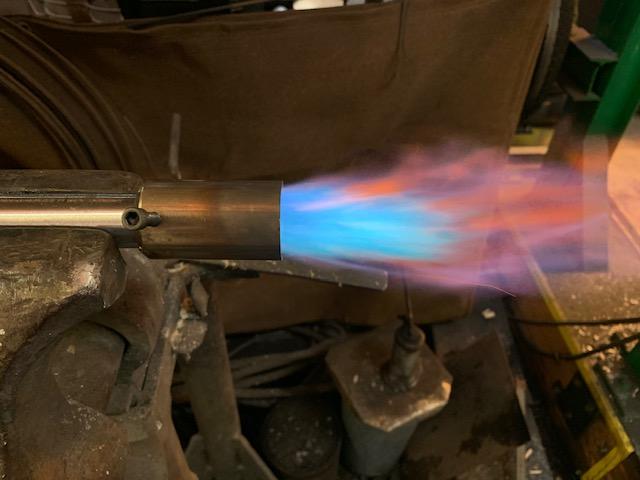
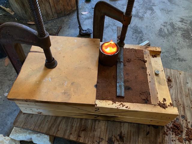
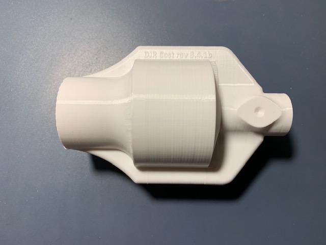
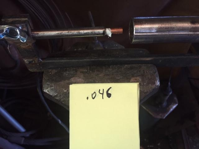
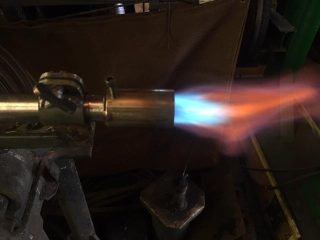
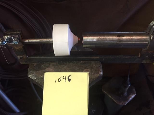
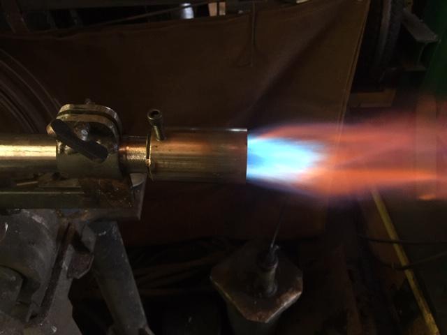
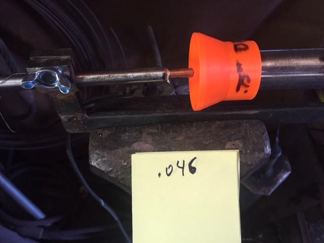
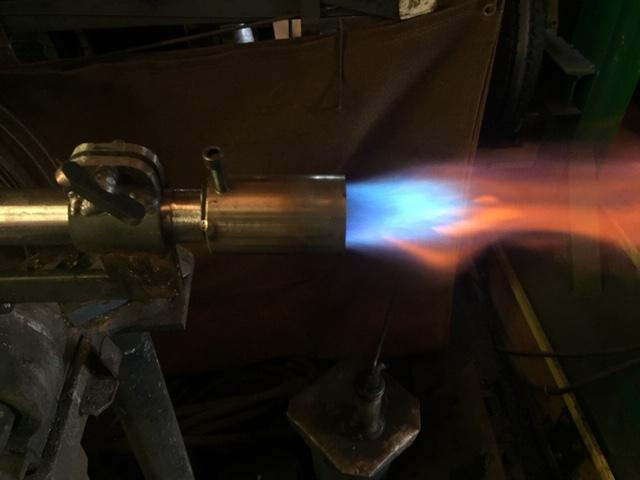
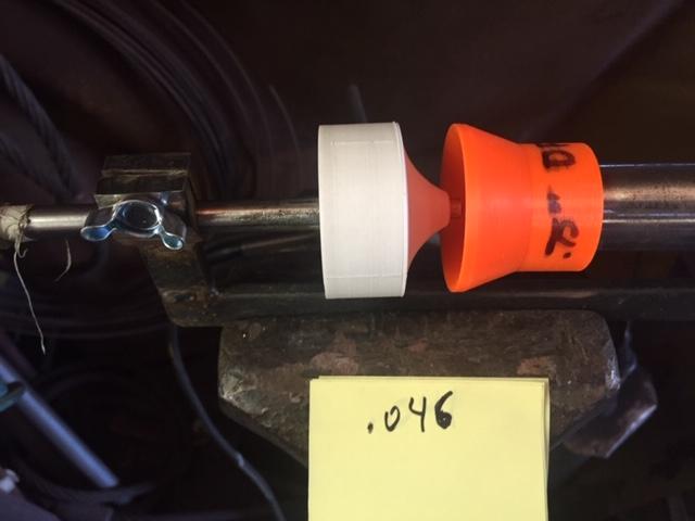
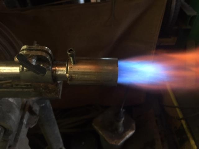
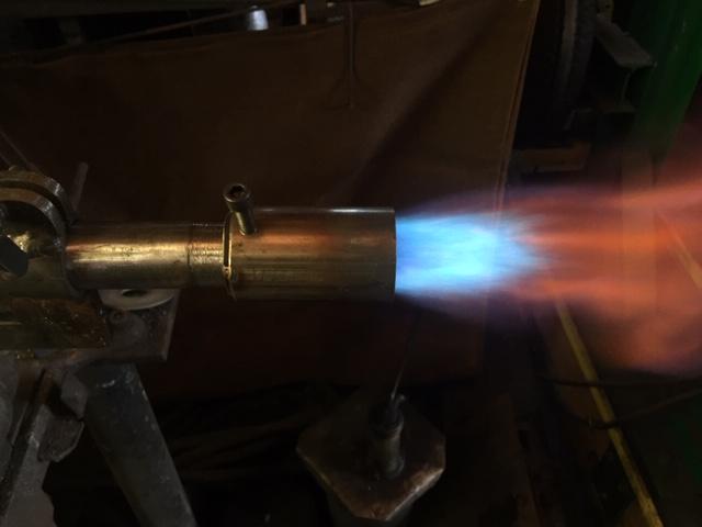
Well, I'm back and have had a bit of time to play. Finally cast by first burner. Here's a pictorial. I'm hoping the pictures will explain why I did certain things: 1-This is the 3D printed mold for the core and the exterior mold (with the gray background). The core mold is clamped together, and the brass rod inserted. The blue tape around the rod will allow me to insert it in the pipe and make sure the jet is straight. The brass rod is 7/16" from the hardware store...it's the hobbyist stuff. A 1/8" schedule 80 pipe (for the jet assembly) fits inside perfectly. -------------------------------- 2-Just the sodium silica and a cup with the sand. 1.5% sodium silicate by weight, but I just pour a little in with the sand. I used to measure, but I have a feel for it now, and it's not too critical, just shouldn't have too little or the sand will not hold together. The sand is a very fine mesh sand I got at a foundry. One bag has lasted over a decade...and it's only about 1/3 empty. -------------------------------- 3-The sand is tamped down a layer at a time. If you put too much in at first, the bottom will not be packed enough. Maybe 3/4" layer at a time. The sand packs down a lot. -------------------------------- 4-Here I'm injecting the sand with carbon dioxide. I run it at about 15 lbs on the regulator. The injector is just a 1/8" brass tube with several 1/16" holes in the sides of the end and the end mostly pressed closed. I don't know it it reads in the pic, but in my hand is just an air blower handle that I attached tubing to. -------------------------------- 5-Here I'm taking the core apart. The sand is almost immediately hardened. It's a quick process. The holes from the injector are not where bronze will be anyway, or I would fill them with either petrobond or some sodium silicate sand. Here you can see the brass tube passing through the core. It's filled with core sand as well and I will be casting over part of it. Brass melts at a few hundred degrees lower, but I've done this before and it doesn't melt. I filled it with core sand anyway to prevent it from distorting. -------------------------------- 6-Here the mold is placed in the mold. The burner pipe is in place, and the blue tape on the brass tube centers the brass rod. -------------------------------- 7-It turned out the burner didn't leave much sand thickness in my box, so I clamped a board on top of the flask to prevent it from breaking due to hydrostatic pressure. I also made a quick cup to pour in to increase the pressure. -------------------------------- 8-Worked the first time! I was truly surprised, castings this complicated usually don't and need some futzing. I was really careful to make all thicknesses the same at .25". And yes Mikey, I did use silicon bronze. I as going to, but was considering aluminum and your comment supported my initial feeling...thanks! It's what I usually cast in since I usually do sculptural castings and have hundreds of lbs in stock. It also make a beautiful cast. -------------------------------- Here's the cast with the core broken out a bit. -------------------------------- In my excitement to cast something, I forgot to cast the choke with it...so here's the choke. -------------------------------- Here's the burner with mig tip drilled out to .046. With the choke wide open, it's a good neutral flame. Stable down to about 1lb on the gauge (or almost not reading), and I took it up to 20lbs on the test (I never go over 15 anyway). -------------------------------- Closeup of the flame at 5 lbs. -------------------------------- Problem is, I put it on my ribbon burner in the forge and it ran really rich. I switched down to a .040 mig tip and voila, it worked great. Seems that the back pressure was too much for it, or for this burner I need a ribbon burner with more holes. Unfortunately, that is the same size jet as my ancient Reil Burner. It may end up that all I have built a really nice looking, chokeable burner. To test, I'll run this for 30 minutes in the forge at 5 lbs, and the Reil burner at 5 lbs and see if there is a temperature difference. -------------------------------- That's it for now! Cheers, DanR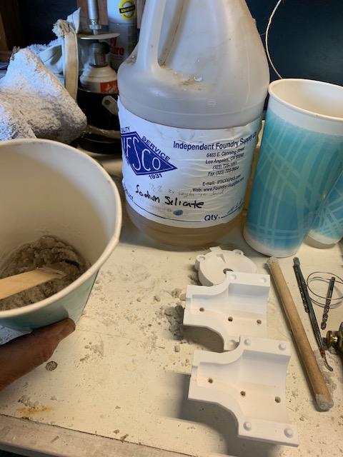
-
Lighting setup for belt grinder
D.Rotblatt replied to FatFrumos's topic in Building, Designing a Shop
I have a 4' fluorescent right over my grinders to provide a general light. I used that many years, and it works well. But a couple of years ago I added a Moffatt 95041 Task Lamp I got from amazon. It is a goose neck lamp with a really nice quick connect base. I have two grinders and can swing it between the two and the goose neck allows it to easily be shifted to exactly where I want it. It's a little costy, but seeing is important, and at 62 my eyes need the extra light (and cheater glasses...). DanR -
Question. Is that long bolt what you made the knife out of, and if so, did it harden? Unless that's something other then a bolt it is at best .5 carbon. As a decorative piece no problem, as a functional piece it won't hold a great edge, but it will work.
-
3D printed plastic burner experiments (photo heavy)
D.Rotblatt replied to Another FrankenBurner's topic in Gas Forges
I love it! Looks hand powered or is there a motor under there? Roller mashes the sand down, arm scrapes it up and off the sides. Simplicity itself! Well thought out and executed. DanR Back from Spain tomorrow, lovin' the trip, but want to get back in the shop and play! -
3D printed plastic burner experiments (photo heavy)
D.Rotblatt replied to Another FrankenBurner's topic in Gas Forges
I’d have to see a picture of the 70degree you are referring to. I assume you’re taking an arc or spline off a 70 degree line for the inlet profile??? Heck, we should swap some .step files (or whatever works). I’m using Autocad Inventor. If interested pm me I’ll be back from my trip early August. Haven’t noticed flame showing much mixture change over .25-15 lbs. range on any of my tests, but I’ll keep a closer eye - I may just have missed it. I agree about not futzing with a choke every time you change pressure. You’re dad is awesome! I did make a sand fluffer (as we called it) to recondition the petrobond when I taught foundry, but always wanted a muller to make my own. Used greensand a couple of times, nice not to deal with the smoke. -
FYI: I've had problems with motor controllers in my shop (harbor freight). when turned down, every time the compressor turns on the motor slows, big flames out of the forge, etc. Admittedly, I've only got 40 amps in my shop and it's pretty maxed out, and it's a Harbor Freight controller. But if you are in a similar situation, be aware. DanR
-
3D printed plastic burner experiments (photo heavy)
D.Rotblatt replied to Another FrankenBurner's topic in Gas Forges
You're beating me to it! Exactly what I'll be doing when I get home from Spain. Petrobond, Sand and sodium silicate cores, etc. When cast should be only one hole to drill and tap. I'll post the design, but it will be one like #4 above with the choke and an integral clamp to hold the jet in place and centered. I'm thinking of casting right onto a 3/4" pipe to avoid having to mill/drill the connection (don't have a lathe). Really hard to get it perfectly straight since the casting is never perfect, but not hard to cast it in place straight! I've got it on paper and in my head....should work great, but the best laid plans and all . -
Naturally Aspirated Ribbon Burner. Photo heavy.
D.Rotblatt replied to Frosty's topic in Ribbon Burners
I am using an old 3/4" Riel style burner. As the number of holes get smaller, the friction is greater, and I'm sure there are a number of variables that come into play. There doesn't seem to be a direct 1 to 1 relationship between area of holes in a ribbon burner and the area of the turner tube. I figured it out by trial and error using Frosty's method of drilling holes in a wood block and trying it out. Started with about 50 holes and worked up to the 122 or so. You get about 1 minute of burn until the wood starts to burn badly. BTW: I'm off traveling in Spain right now, so I won't be answering much until I get back early August. -
I assume you have the chokes all the way open (I'm sure you do, but pays to ask). Did you use tape on the joints? If so pull the mig tips and make sure they are not clogged...a common problem to get little bits of tape stuck in the tip. Pays to do that anyway to make sure they are not clogged but if both are acting the same that would be quite a coincidence. It should be pulling the right air. Those are 1-1/2 x 3/4 reducer fittings? You're running at about 5 lbs pressure or so to test? Did you shorten the MIG tips? if so you probably need to ream them out with a torch tip cleaner. I seem to keep coming back to the jets.... If they are not blowing, or blowing in the right direction they will not entrain enough air. If you look directly down the burner, are the tips pointing straight down or off to the side? Once more, both burners are acting exactly the same? It is a quandary.... Listen to Mikey....look at Ron Reils site, that is basically what these burners are. Note - looking at your picture, pull the burners up so they are above the level of the wool. They will just burn off in time located so far into the forge. DanR
-
3D printed plastic burner experiments (photo heavy)
D.Rotblatt replied to Another FrankenBurner's topic in Gas Forges
Thanks Brijasher! Inlet air depression...got it! Interesting explanation, Thanks! DanR -
One thought. How long are you letting the forge heat up? If you have a thick layer of cast refractory on the kaowool (even 1/2" or more) it will take time for your forge to heat up. It has to run long enough to heat up the refractory. I lined one that way with about 3/8-1/2" and it took almost 30 minutes before it got to temperature (i.e. stopped increasing temperature on the pyrometer). That's why I use an eggshell technique to cover the kaowool. The advantage of the thicker refractory coat is that it is stronger and more forgiving then the eggshell, and retains more heat so keeps a more stable temperature. YMMV DanR
-
A couple tips about forge welding cable in addition to what Frosty said. Use the step on the anvil rather then the face so there is pressure on three sides and turn it in the direction that it is twisted as you forge weld it so it tightens the twist. I also mig weld the ends so it stays tight. DanR
-
3D printed plastic burner experiments (photo heavy)
D.Rotblatt replied to Another FrankenBurner's topic in Gas Forges
I would, but one of the primary parameters is that the end result be easy to sand cast. I have a CNC mill, but no lathe. There is also a limit to the length that I can print on my 3D printer. I could fabricate a sheet metal cone to try it, but it would not be an easy build to replicate. That was the idea in what I call the "Wasp" burners...those with a waist. Some of the 1920 designs are shorter and my longest ones replicate these. According to the 1920 stats on them, they are almost as efficient as their best ones which are longer. DanR -
3D printed plastic burner experiments (photo heavy)
D.Rotblatt replied to Another FrankenBurner's topic in Gas Forges
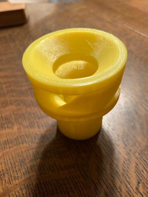
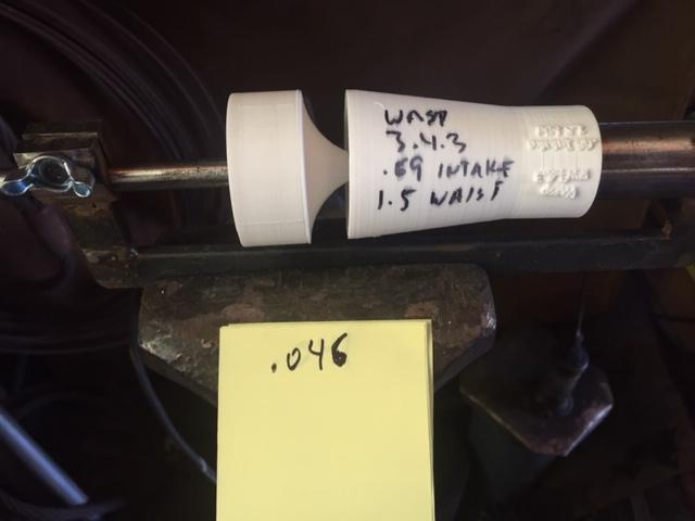
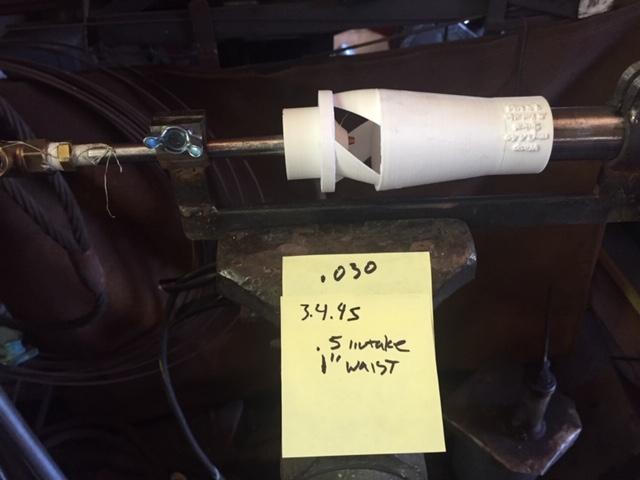
Continued experiments on printed injectors. As I played with the designs, I found that the larger the opening the better it seemed to work. Is the wasp waist even worthwhile? So I ran a series of tests with the burners I had to see if I was going in the right direction - from no injector to a couple of my best. Here's an overview of my thinking so far: there are 3 areas that area variables in the injector. A) I'll call this the intake. This correlates to the bowl shaped part of the pipe reducer in the Reil Burner or other plumbing made burners. The intake can be made in one of several shapes. Either concave sides like a plumbing reducer, flat like the 1920 article pic below, or convex like in my burner. a sample of my burner: Pics from a 1920 article: b) The size of the opening, and C) the waist. The waist can either be nonexistent (in which case the opening will terminate on the end of the pipe) or can taper like in a burner nozzle (or see both pics above). A smaller opening then the size of the pipe will be required to allow the waist to taper. It is a trade off. If you want a lot of taper, or a long waist, you need to make the opening much smaller then the pipe. The idea of the waist is to create the bornouli effect and increase the speed of the gas, decrease the pressure in the opening and pull in more gas and hopefully mix the gas. Here's the problem in real life, as I was playing with different sizes in the variables, I found that in order to make a waist or much of a taper, I had to make a smaller opening. All of the permutations had very good flames, but as the opening increased, more air was pulled in and I had to move up to larger and larger mig tip sizes, from .030 with a .5" opening, to a .048 jet with a .75 opening. It appeared that the larger openings were more efficient. I began to wonder if a waist was necessary at all. So I tried a series starting with no injector at all and adding the variables one by one (if possible). All were at 5 lbs psi on the gauge with the same jet size, I tried to position the jet around the same distance from the injector. All the injectors work well from nearly 0 psi to 15 psi on the gauge. I don't know what the yellow flames were. Something burning or being blown through the burner. ___ 1-No injector at all. Just a jet in front of a pipe. Actually a rather decent flame, considering. Primary flame is feathery but a bit unstable. ___ 2-I added my choke plate. It didn't make much difference, but it did allow me vary the fuel mixture if I wanted by moving the jet forward or back. ___ 3- This injector is an early one. It has no waist, and a .84" opening (the ID of the 3/4" pipe) and convex sides (much like my picture above). The .75" marking refers to the length of the intake. If you compare it to pic #1 you can see it created a larger and much more stable flame. ___ 4-Here I added the choke. This produced an even bigger and smoother flame. I seems the combination of the two focuses the air even better then the intake alone. The flame went a bit lean here, so a larger jet size would be possible. Maybe .048". ___ 5- in this test I used the best of my wasp injectors. The flame is a bit smaller, and a bit rich, but the opening is only .69". This burner works best with a .042 jet rather then the .046 jet I have on it. The smaller flame is due to the smaller opening. ___ 6- Not a good comparison, but this is similar to the burner above, but with a spiral intake, .5" opening and 1" long waist. Because of the smaller opening (and the spirals which also restrict air intake), this burner uses a .030 jet size. I found the spiral intake produced a fine flame, but not at low pressures where the spiral motion of the gas down the pipe caused the flame wobble and to be more unstable. It would probably work fine inside a forge. _________________________________ CONCLUSIONS: 1: To my relief, the injectors are increasing the intake of air significantly. The shape of the intake may be important (the next variable to play with). 2: The choke also added to efficiency a surprising amount and is a fortuitous discovery. I don't know why, but this is good since I really like to be able to reduce the mixture of the gas. The concave sides of the choke pretty much mirror the convex sides of the intake creating a kind of funnel for the air. 3: A waist, because it requires a smaller opening, decreases the volume of air being pulled in, thus creating a smaller flame. The characteristic of the flame is, never the less, very good. But the flame is not better then a similar injector with no waist and is thus, less efficient. 4: The spirals around the intake restrict air flow (I tried a few exact same burners with and without spirals and the ones with spirals required smaller jets) and cause instability at low pressures (under 1 lb PSI). This is contrary to Another Frankenburners experiments, but my spirals may be different than his - I copied them from his pictures. Further, I have a moveable choke while he doesn't. ***A burner like the one pictured in pic #4 had the largest flame at the same psi and jet size. It would also be very easy to sand cast (which is one of my requirements for this experiment). The larger the opening, the more air the burner can pull in, the larger the jet size required, the more efficient the burner. Thus a burner with the largest opening is ideal. ***The moveable choke/jet design allows both for adjustment of the mixture and for ease in casting. The burner and choke can be cast in two pieces. This would have worked even with the spiral style of burner, but I don't think I'll be moving in that direction. DanR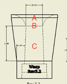
-
My forced air is more of a breeze out the ends, for regular forging I have the blast gate closed about 3/4 or more...and I don't have a large fan on it. It'll still weld, but I put a larger fan on it for bigger stuff. The more I read, the more I think you just have too much air, thus a very very lean mix. I'll lay money on a blast gate (or similar) getting it under control. Dan R