D.Rotblatt
-
Posts
335 -
Joined
-
Last visited
Content Type
Profiles
Forums
Articles
Gallery
Downloads
Events
Everything posted by D.Rotblatt
-

Naturally Aspirated Ribbon Burner. Photo heavy.
D.Rotblatt replied to Frosty's topic in Ribbon Burners
Just used some Mizzou for a burner head. Because the aggregate makes it very very difficult to put between the sprues, I sifted it out with a screen. A little of the aggregate went through. I did the first layer without aggregate, and then added a little to the rest except the last layer. I mixed small amounts at a time. I'll let you know how it holds up. The aggregate in Mizzou is really hard stuff - maybe ceramic or firebrick or a hard high temp stone. Either way, morter and pestle didn't do squat, metal tube with a 1" steel bar did some, but had to do so little at a time it wasn't worth it, finally relied on pounding some with a hammer to pulverize it - but it flew all over. Pain in the rear! I ended up with a bit of smaller stuff, which I used in small amounts. I thought of using some other material which is smaller. I have several grades of fused silica for ceramic shell, but I didn't want to add something that might be a lower temperature melting point. Also tried breaking up a IFB, but it mainly powdered, and I wanted small bits of aggregate rather then the larger ones in the Mizzou, so that was a bust too. I'll have to test the fused silica and see if it slumps at high heat. DanR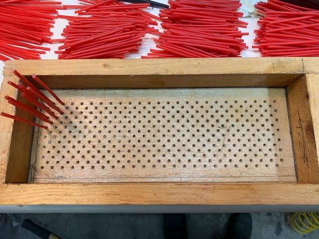
-
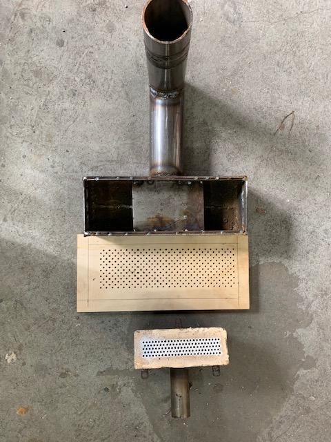
I've posted in the NA ribbon burner section about my NA burner with 124 holes at 1/8" each. This burner is awesome; it does not backfire at all at any pressure (even down to shutting off - the flame just stops drawing air and goes to pure propane), with the same burner I use as the injector it gets the forge 100 degrees hotter, the flames are so small I can point them down from the top and the gas is fully combusted well before it's near the metal, I can turn it down to barely running which is about 1460F - great for heat treating, or I can turn it up to evenly heating the forge to 2350 or more for forge welding. Now I don't like to forge weld in this forge unless I don't use flux (I often do fluxless welding), but sometimes I do use flux for wrought iron and such. So the other day I was doing some wrought iron, and was using my larger ribbon forge and it just wasn't getting to heat like my little one does without hogging up the propane. It's a gun burner (has a blower) with standard crayon size holes. I decided to upgrade it and make a larger burner that had 1/8" holes to see how it works. The new burner about 11x x 3.5". That gave me room for 336 1/8" holes. Here is the burner shell and the wood drilled to receive the 1/8" sprue wax for the holes. I have a cnc mill, so that made drilling the holes easy, but I could have done it with the drill press...set up with the CNC is pretty time consuming. Below the wood form is my little NA ribbon burner. It has 124 holes. Here I'm putting little 4" pieces of sprue was into the form. The sprue wax is in the back in piles of 100. Yes...it was a pain to stick them all in. I bought 3 lbs of sprue was from Duoglas & Sturgess (which is at artstuff dot com) for about $30 including shipping. Enough to make a number of these burners. No pics of putting the refractory in...but here's the gist of it. The form was first painted with Vaseline as a release from the refractory. I'm using Mizzou refractory. One of the problems I had with my NA burner was that the mizzou has chunks of aggregate (probably ceramic or firebrick) which don't really fit between the was sprues well. I spent a long time swearing over that little guy. And no...it doesn't nicely spread out when vibrated, the aggregate is caught by the sprue and it forms clumps that push the sprue apart. The only way I found to get it in place was to put small amounts in an area and push them into place with a knife. So this time I sifted the Mizzou through a screen and separated out the aggregate. I started with a small amount (maybe a couple of cups) and made it over wet. I poured this over the top of the sprue and tried to vibrate it down...it clumped and pushed the sprues apart. <insert well chosen words here> I futzed with it with a knife and finally got the sprues pretty well lined up. Then I used a little aggregate and made small amounts at a time and added them about 1/2 teaspoon at a time. This worked pretty well. The key was to work in small amounts - about 1 cup or so. I put a final layer of Mizzou without aggregate on the sprue area to build up and even out the top (which will be the inside) and vibrated it down (which worked well to create an smooth top, but the sprues prevented high points from vibrating down). Then I used regular mixed mizzou but with extra water to fill in the sides around the sprue (there is about 1/2" gap) until it is up to the level of the wood. Do not vibrate until the metal shell is pushed into the mizzou or the aggregate will lock together and you won't be able to push it down. Tapping the side with a hammer helps as you are pushing it down. I put a couple of C clamps on to hold it all together and I bagged it up and it's setting now. I'll pull it apart in a couple of days and report on the burnout...with some pics! DanR

-
3D printed plastic burner experiments (photo heavy)
D.Rotblatt replied to Another FrankenBurner's topic in Gas Forges
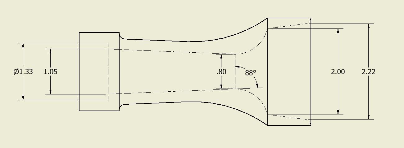
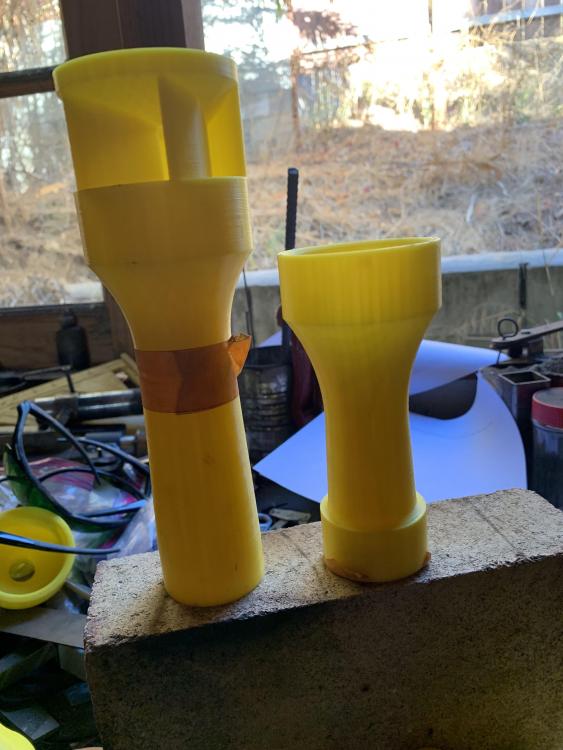
I got a chance to try the wasp waisted burners with 3/4" opening flaring to 1" tube. The reducer is the same as my best reducer. The one with fins is the same reducer with fins shown in the diagram in an earlier post. The choke is shown in the second pic. Didn't have the camera with me to take pics of the test but here's the results. 1) Pulls a lot more air, I had to move up from a .046" mig tip to a .056" mig. 2) Flame was stable at higher pressures, but huffed at 2.5 lbs and lower. This is consistent with what I would expect of the flare. The gas velocity is decreasing as the tube flares, so as the pressure is turned down the FAM burns back at higher pressures than in a straight tube. 3) On the one with fins, the flame was smaller and even slower, thus it huffed at 3.5 lbs. The fins imparted an extreme vortex to the flame causing it to feather out a bit (but not as much as AFB's version of G-Son's idea). If the choke was in far enough in for the back hole to be open, the vortex virtually disappeared. When closed with tape it worked again. The flow of gas wants to come from parallel to the burner tube which is consistent with my observations using smoke on open burners. 4) I have no idea if this applies here, but I was reading about Venturi (or restricted pipes like this) being used to mix fluids. This might work to help mix the propane/air. Conclusion: For a forge, this would be a failed direction due to the poor low pressure results. For a furnace, this would be an excellent choice. Is it better then a 1" Straight burner? Would have to try it and see. For now, I'm taking a break and rebuilding my gun burner longer ribbon forge to try a massive burner with 336 holes @ 1/8" each. I'll put it up in the ribbon burner section. Got it invested and setting now! Pic below. My little 124 hole NA burner is next to the board with holes. DanR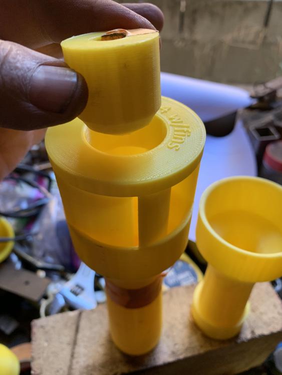

-
3D printed plastic burner experiments (photo heavy)
D.Rotblatt replied to Another FrankenBurner's topic in Gas Forges
This is a picture of a Venturi tube. It's basically the same shape as our burner. But the lower pressure area created by the constriction does not pull air in from the direction of the flow, but instead would pull air/gas/fuel from a tube in the side (like the tube showing pressure differential which is actually the outside pressure pushing the liquid into the constriction). So, when you are saying there is NO Venturi effect in operation, you are saying it does not apply to our situation, the flow of air is imparting the energy to create the low pressure zone, rather than the low pressure zone creating the flow of air. I guess if it did pull air, we could blow in one end and it would continue to run by itself...a perpetual motion machine. Just because you asked...With the pitot tube, there is no restriction in the tube so it doesn't have anything to do with Venturi. But to equate it; instead of inside, the "restriction" is on the rounded outside of the tube. Take the Venturi tube shown above, split it down the middle horizontally, and put the bottom half on the top - you now have the pitot tube. It's basically an inside out Venturi tube. It's not the Venturi effect since it's not a constricted tube, but it is a nice application of Bernoulli's principle (singular ). DanR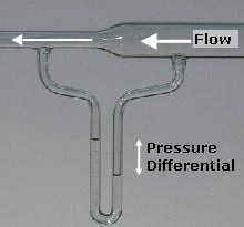
-
3D printed plastic burner experiments (photo heavy)
D.Rotblatt replied to Another FrankenBurner's topic in Gas Forges
Yes, I quoted social media about scientific principles...sigh....you may whack me upside the head should we ever meet. DanR -
3D printed plastic burner experiments (photo heavy)
D.Rotblatt replied to Another FrankenBurner's topic in Gas Forges
Thanks Mikey, yes. I didn't really address rotational motion of the reducer shapes themselves. If I could pick your brain on this: What is the difference between a swirl and vortex? And if they are basically the same, is there a practical difference? Though already probably talked about, from what I've read, the coriolis effect is practically non-existent for small systems like we are using. It's complicated, but air/liquid flowing straight into the funnel is a higher energy system then flowing in at an angle, therefore we get angular flow or a vortex. The direction being dependent on irregularities in the system. Mikey burners, 'T" burners, AFrankenburners create the irregularities or obstructions that enhance this angular motion, so I assume this is what you mean by 'swirl'. Is this correct? DanR -
3D printed plastic burner experiments (photo heavy)
D.Rotblatt replied to Another FrankenBurner's topic in Gas Forges
Let's see if my application of these ideas to our burners seems reasonable. I used to teach science in middle school, but that hardly gets into any fluid dynamics. So Bernoulli states (via wikipedia): "Bernoulli's principle states that an increase in the speed of a fluid occurs simultaneously with a decrease in pressure or a decrease in the fluid's potential energy." while Venturi applied that to a constricted pipe shape: "The Venturi effect is the reduction in fluid pressure that results when a fluid flows through a constricted section (or choke) of a pipe." As you stated Frosty, the Venturi effect is Bernoulli's effect applied to a specific situation; a constricted pipe. I've found that a jet shooting gas into a plain straight 3/4" pipe without any reducer got a pretty good, stable, serviceable flame. There is no constricted pipe around it the entrance, just open air. This is totally the Bernoulli effect? the gas jet moves the air around it faster and this creates a low pressure area that sucks in more air. It was actually kind of disheartening, since we are spending all this time on our reducers. The reducers do stabilize the flame at lower pressures and do a lot to fine tune the flame. I'm imagining that they focus the air allowing an even flow and more stability. We are adding fins to increase the vortex effect. As I understand this, propane is difficult to mix and the intention of this is primarily to aid in mixing. The fins would not increase induction of air into the tube. When we get into Wasp waisted burners we should be looking at some venturi effect coming into play as well since we are going into a pipe that the restriction lessens after the neck . The air pulled into the pipe through restricted neck and then travels out an enlarging cone where it will slow down. The way I see it is that this will slow any vortex, and the gas will exit the pipe at a slower velocity. It will also take more time to exit the pipe, perhaps allowing more time to mix? I've got some 3D printed, but need to make a new test rig with a 1" pipe to see what they do. Should get that done this week. Lot's of variables. Lots to play with. DanR -
3D printed plastic burner experiments (photo heavy)
D.Rotblatt replied to Another FrankenBurner's topic in Gas Forges
Ah! So you are talking about a change in radius? If I could reword that to see if I’ve got it: in our burners, the gas jet creates a low pressure zone the air is sucked into, while in a Venturi (like an SU carb on my Spitfire) air is sucked into the intake (like by a vacuum created by a moving piston) which forces it past a necked area in the venturi creating an increase in velocity and a low pressure zone which in turn pulls fuel into the air steam. Given that there is no actual pulling or “sucking” - everything is actually pushed by higher pressure air behind it. But we tend to think of it that way and it’s easier to describe. -
3D printed plastic burner experiments (photo heavy)
D.Rotblatt replied to Another FrankenBurner's topic in Gas Forges
Great post. Still digesting it..will have to read a few more times. One question: don't you mean here that "Increasing the intakes radius must decrease the velocity of the vortex" - when a skater pulls his/her arms and legs in they move faster, arms out they move slower. Correct me if I'm wrong...It's not unusual Looks like a kiln burner. I have a few of those laying around. DanR -
3D printed plastic burner experiments (photo heavy)
D.Rotblatt replied to Another FrankenBurner's topic in Gas Forges
As many things so, the nomenclature works great until you step outside the box a little . I was amazed that just because of this I was limiting myself to a preset tube size...just following the herd.... Says something about the power that giving something a name has on our psyche. I guess I was just trying to keep things modular. That's what I'm using on my new burners. If you are getting that with a 1/2" opening and getting a neutral flame, I might have to give one a try...Hmmmm.....back to the Inventor for some designing! I'll post when I get them! Thanks for your input! DanR -
3D printed plastic burner experiments (photo heavy)
D.Rotblatt replied to Another FrankenBurner's topic in Gas Forges
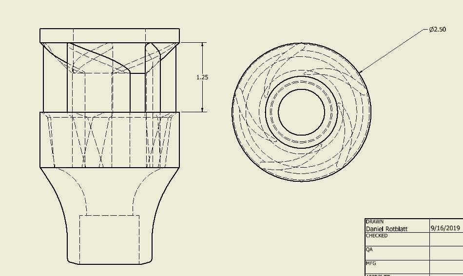
So all this new discussion has given me some things to think about. In all my experiments with wasp waisted burners, I kept the maximum output at 3/4" since I was trying to make a 3/4" burner. This reduced the intake down to 1/2" depending on the length of the out-take funnel. In looking at the pic from Frosty on the previous page, I realized that I was painting myself into a corner, and what I could to do was create a burner with a 3/4" intake, and allow the funnel to enlarge to 1". Now here's the question....is this then a 1" burner, or a 3/4" burner? Either way, the smaller wasps worked well, just had a much smaller flame (Due to restricted intake). So I'm making this (printing up now) with the intake that I have that works best (rev3.4.1): Then...All the discussion about the rabbit cage version by G-Son, I wondered what would happen if I added something like that to my 3.4.1 burner. These are printing up as well (a 16 hour print...): Higher fins, same intake, top with hole to allow for choke, 3/4" output pipe. I'm also printing one with a 3" wide intake so the fins are further from the center. I'll let you know when I test it! DanR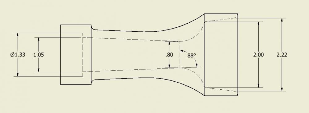
-
3D printed plastic burner experiments (photo heavy)
D.Rotblatt replied to Another FrankenBurner's topic in Gas Forges
A short flame with dispersed heat might be just the ticket for a forge. Apart from the radiant energy going out the doors, a lot of heat in a forge is the radiant heat from the walls and this type of flame would heat a wider area. Also the short flame will keep air off the metal preventing oxidation (scaling). I'm interested to see how it does in a forge! I love a good investment cast...you can see all the lines from the 3D printer! FYI: If you want , you might try spraying the print with lacquer or shellac to even up the surface (we used that for waxes of sculptures to fill pinholes, etc before investing). DanR -
Perfect! Sorry if I assumed.... DanR
-
3D printed plastic burner experiments (photo heavy)
D.Rotblatt replied to Another FrankenBurner's topic in Gas Forges
If you want vortex, you got it! Looks pretty cool. Now to balance it with the maximum air entrainment. Two thoughts: What about making them taller? I've observed that the air moves fastest down the center around the MIG tip. If you look at side draft burners like Frosty's 'T', the opening is pretty large/high. Making them taller allows for less of an angular flow. Second; You could also angle them in towards the center a bit more and use a few less of them which would open the gaps. I think Mikey was suggesting 3. Just my thoughts. DanR -
Looks good, don't worry about the pull away it won't make any difference. The burner nozzles (I assume that's what the 2 red projecting tubes are) should not project beyond the refractory. In fact they should be recessed a little bit into the refractory. The heat will cause the ends to oxidize and deteriorate quickly. I generally recess the ends into the refractory by 1/2" or more. I mold the liner by hand around from the nozzle end to the inside surface so the hole forms a slight widening taper. DanR
-
3D printed plastic burner experiments (photo heavy)
D.Rotblatt replied to Another FrankenBurner's topic in Gas Forges
I'll do a temperature test in the forge and see which one is better. I was going for larger flame, but you may be right about a shorter flame working better assuming efficient burning. That's why the ribbon burners work so well, very short flames which allow complete combustion in a short area. DanR It's working great. I'm going to rebuild the gun ribbon burner in my larger forge to be a 10 x 3.5" with 250-350 1/8" holes burner coming from the top of the forge (it's a crayon sized hole one coming from the side right now). I was forge welding with it a few days ago and I didn't realize how well my little NA burner (from the pictures) was working. I was really having to crank up my large forge, and it wasn't really reaching the heats that the smaller NA was. The beauty of the small holed ribbon burner is that even a large burner can be turned down to really low pressures and still work. DanR -
3D printed plastic burner experiments (photo heavy)
D.Rotblatt replied to Another FrankenBurner's topic in Gas Forges
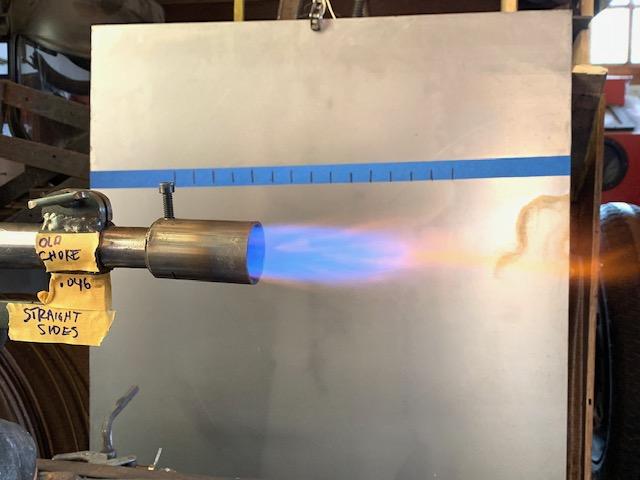
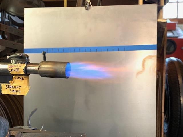
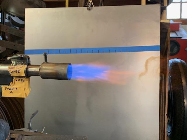
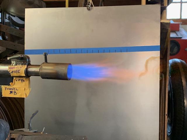
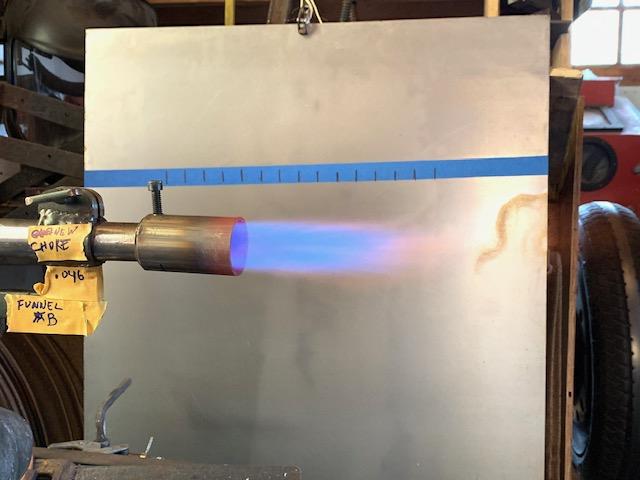
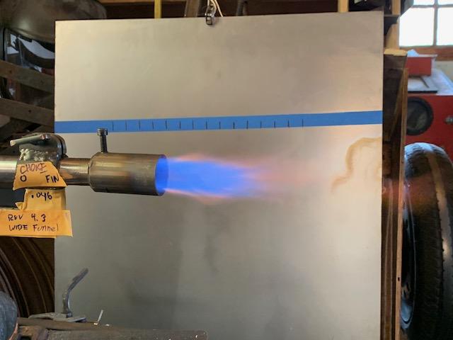
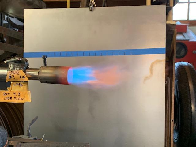
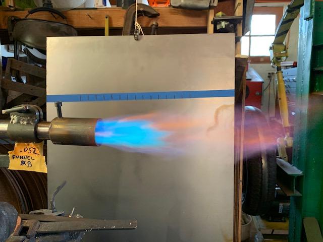
A quick pictorial of some more tests. First set with the NA ribbon burner out of the forge. 5 lbs, tip size and reducer written on tape. Upshot, Funnel A or B worked best. I went with 'A' for a bronze pour as it is "good enough" for now. The wide funnel reducer was tried with a choke with no fins, and 2, 3 and 5 fins. All created a poorer flame then any of the other ones. There was definite vortex motion of the flame leaving the nozzle on all the finned versions, with more vortex produced by more fins, but smaller flame as more fins were added...i.e. there was a cost to inducing vortex. The vortex could be seen by looking down the nozzle when lit, and the flame straightened as soon as it left the nozzle. Here's the reducers tested: _________ The chokes with the fins shown in the bottom are sized and used on the "wide funnel" burner. The wider shape is intened to allow more air to be induced. All but the last are with .046" mig tips shortened to about 1/4" long. This made a huge difference between the same mig tip .675" long. The flame color is weird on my phone camera. I adjusted the choke in each for the best flame I could. _________ This is the straight sided reducer with the old choke, which is wider then the new choke in used with the same reducer in the next pic. _________ _________ _________ _________ _________ _________ _________ _________ __________ This is using the no fin choke with a .052 mig tip. The flame was a bit rich, so this tip was too big. DanR ======================================================================================================= Yes, that's correct. Sandblasting after casting. Since it's a sandcast the cores are never really fired in this case. This stuff is nothing compared to ceramic shell, that stuff is awful to get out; sandblasting, needle hammers, hammer and chisel, whacking the piece with a hammer to fracture it out - nothing works very well. DanR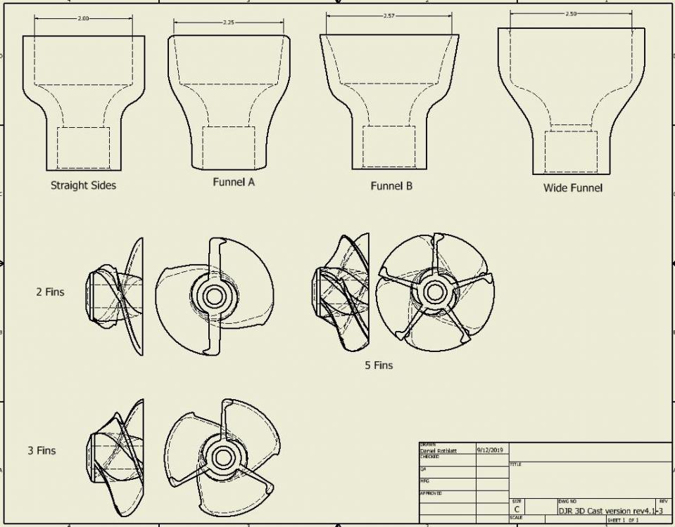
-
3D printed plastic burner experiments (photo heavy)
D.Rotblatt replied to Another FrankenBurner's topic in Gas Forges
Too little sodium silicate, wrong sand, or let it sit out too long (it’s hydrphilic), and it will be crumbly. Vibration not so great, dissolves like snow under a stream of “hot liquid” when sandblasted. DanR -
3D printed plastic burner experiments (photo heavy)
D.Rotblatt replied to Another FrankenBurner's topic in Gas Forges
I’m using sodium silicate and sand for a core. It sets like sandstone, so if there’s a draft on the fins they’ll pull out easy. DanR -
3D printed plastic burner experiments (photo heavy)
D.Rotblatt replied to Another FrankenBurner's topic in Gas Forges
After making the last casting with a core, I’m thinking that a sand cast of your burner head is absolutely doable. The core is basically the funnel with fins, a brass tube to hold it on center. Doable.... DanR -
3D printed plastic burner experiments (photo heavy)
D.Rotblatt replied to Another FrankenBurner's topic in Gas Forges
I’m running all these on a rest rig with single nozzle as well and comparing flames, but I agree that the right angle and plenum aid in mixing. But that said, I feel the temp difference between single and multiple nozzles is in better combustion. A single nozzle burner has a central flame cone of ~4” long and 1+” wide, while the multiple nozzle flame core is about 3/4”long and 1/8” wide. These small flames are also sandwiched between other flames. In a single burner the flame isn’t finished combustion when it hits wall or floor, while the ribbon burner flame is completely combusted half way to the floor (mine points directly down). This does support the need for better mixing in single nozzle burners which in turn support the benefits for inducing a strong vortex. Just kind of thinking out loud here... DanR -
3D printed plastic burner experiments (photo heavy)
D.Rotblatt replied to Another FrankenBurner's topic in Gas Forges
What I am finding in my experiments tinkering is that it is all about volume, not creating a vortex. Contrary to prevalent opinions, I am finding that any fins or blockage seem to decrease output. It may be that I haven't found the "sweet spot", but so far the results have been consistent with this observation. It may be that the funnel shape of the burners creates enough of a vortex that the gas mixes "good enough" and is already in that sweet spot. Given that, I will try one more experiment with a larger diameter funnel and choke with fins so the area of intake is consistent with the one I have now with no fins. DanR -
3D printed plastic burner experiments (photo heavy)
D.Rotblatt replied to Another FrankenBurner's topic in Gas Forges
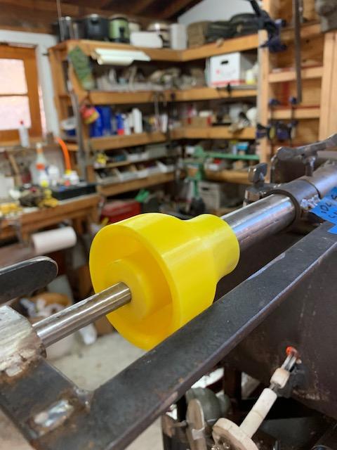
Our two burners are different beasts. I ran another temperature test with my burners. Same jet assembly (except on the reil burner), and same 5 lb gas pressure exactly (used the ball valve to turn it off, same forge. Tried a quick test of my ribbon burner vs a straight single burner (the ribbon burner was far superior - a couple of hundred degrees). A summery of the results: -The new burner (3D printed with 1" lip), with a choke without fins was the best so far getting to 2300F. -Adding fins to the choke on the new burner decreased the temperature. -The Ribbon burner far exceeded the single nozzle burner with the same injector assembly (the bronze cast one) by 200F. _____________________________________________________ The results of the test are below. The set-up is 5lb pressure, .046 mig tip ( trimmed to about .25" long), Modified NA ribbon burner (the one with 1/8" holes described in the NA ribbon burner section). I used the same jet set-up (which is removable) and just swapped it out between the test rig for the new yellow burner, and the bronze cast burner. Each test was allowed to run until the temperature stabilized. Bronze cast burner - 2260 Yellow Burner with 3 fin choke - 2268F Yellow Burner with 2 fin choke - 2272F Yellow burner with choke (no fins showed below) - 2300 _____________________________________________________ This is the best test. New burner on test rig with plain (no fin) choke: ____________________________________________________________ I also ran the burners with the ribbon burner out of the forge. Larger flames on the Yellow Burner injector. I got pics and can post if you like. DanR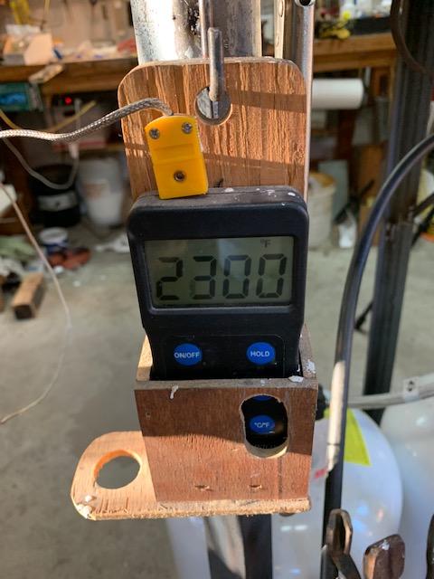

-
3D printed plastic burner experiments (photo heavy)
D.Rotblatt replied to Another FrankenBurner's topic in Gas Forges
I'd love to see. The straight section after the intake fins? Your burner is so different that I'm not sure what it will do...will be interesting to see! -
3D printed plastic burner experiments (photo heavy)
D.Rotblatt replied to Another FrankenBurner's topic in Gas Forges
Just give it a few taps to loosen it and slide it out (at least that's the theory...). In the "old" days, one of the foundry tests was to sand cast a spoon, cup and saucer in one piece. http://schoepp.hylands.net/coffecup.html if you want to see how it's done, pretty impressive. DanR