HojPoj
-
Posts
290 -
Joined
-
Last visited
Content Type
Profiles
Forums
Articles
Gallery
Downloads
Events
Everything posted by HojPoj
-

Advantages of using a needle vaulve in an idle circuit.
HojPoj replied to archiphile's topic in Gas Forges
Needle valves allow very fine control, ball valves not so much. In other applications you'd have a ball valves inline with a needle valve so that the needle can dialed in to the desired setting, and the ball valves used for on/off. -
Did you happen to take any pictures along the way? It could go a long ways towards helping to troubleshoot.
-
Is the pan itself actually getting hot enough to glow?
-
You'd be surprised what TSA is ok with. Once on a trip I got to fire an M240, I re-belted the expended shells and packed it in my bag. I've also brought spices in unmarked containers as well for the long trips.
-
First day of blacksmithing!
HojPoj replied to fangedknight's topic in Blacksmithing, General Discussion
Tangential question: is the blowback as much of a concern with commercial charcoal? I thought that was more of a concern with coal since the coking process produces a lot of volatiles. -
ID, another machine to look at for potential parts are exercise rowing machines. They probably use the same sorts of hardware you're planning, but I've seem some that would great to hook in your treadle arrangement. The rowing handle is attached to a chain that goes over a one- way bearing with a sprocket on it. As I recall the hardware on the rower looked a bit beefier than the one way bearings I bought, though it might've just been a larger shaft size.
-
MotoMike, Tertiary flame implies that there's still additional oxygen present (or being drawn into the forge through leaks around the burner) that isn't combusted in the primary or secondary flame envelopes. With a tertiary flame present, that oxygen will have opportunity to react with the piece contained in the forge.
-
New Ridgid #165 or old PW #240 - which one?
HojPoj replied to Rojo Pedro's topic in Anvils, Swage Blocks, and Mandrels
I recall that, moreover recall having to be real careful not to get my thumb caught reloading it. Just didn't catch the reference because there should be more PEWs! -
Dunno if they're drilled, or formed on a mandrel. Regardless the finish seems to be better than fresh off the lathe.
-
If my foggy memory of fluids is correct, laminar flow is roughly at about 12x the diameter of the flow passage- sometimes shorter if the lead-in geometry is meant for the task. The bigger problem with drilled orifices is that they tend to get burrs or something other than a nice, sharp-cornered round hole. These irregularities can actually cause the gas jet to be pointing in a different direction than the hole was drilled, or be distorted and turbulent, thereby affecting the draw of combustion air. .
-
Daswulf, what do you use the star point chisels for? I've got a couple and no intention of doing masonry by hand, but didn't know what they're typically made of for the sake of repurposing.
-
New Ridgid #165 or old PW #240 - which one?
HojPoj replied to Rojo Pedro's topic in Anvils, Swage Blocks, and Mandrels
If it's taking that many 'pews' before a PING then something is amiss. *insert joke making thinly veiled connection between hammer control and sight picture/trigger squeeze here* -
Welding on an S7 Face Plate
HojPoj replied to bajajoaquin's topic in Repairing and Modification to Anvils
It looks like you have an idea of what you want to do, particularly with that sketch. I have to ask, have you mocked that up to see just how big a gap that would be just to fit the MIGs tip in and move it into the needed angles to get a complete fill? That limitation may answer whether you want to bother with that particular procedure since the amount of filler materials could really start to add up. Personally, I'd go with the proper buildup for S7 hardfacing- at least you can see where you're likely to have missed spots or porosity. Still not a walk in the park, though. Having not worked on a nice clean, hard anvil m'self, I cant speak to whether there's appreciable difference between just a hard skin or a hard substrate, as well. -
What did you do in the shop today?
HojPoj replied to Mark Ling's topic in Blacksmithing, General Discussion
Rather than a rigid object, perhaps something limp or flexible... like a bit of chain? Would make things seem even more organic, at least in my head. -
A collection of improvised anvils
HojPoj replied to Charles R. Stevens's topic in Anvils, Swage Blocks, and Mandrels
There may be an appreciable difference between the Lincoln and a Harbor Freight unit along with the challenge of the different alloys (I'm pretty sure the 1.75" base is mild, whereas the rail must be somewhere higher in carbon content). My first attempts cracked right away, but I'll experiment a bit with the offcut and see if I can get it to stay. -
A collection of improvised anvils
HojPoj replied to Charles R. Stevens's topic in Anvils, Swage Blocks, and Mandrels
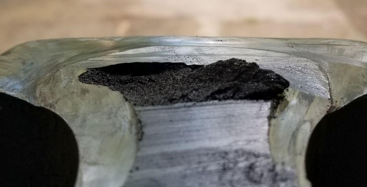
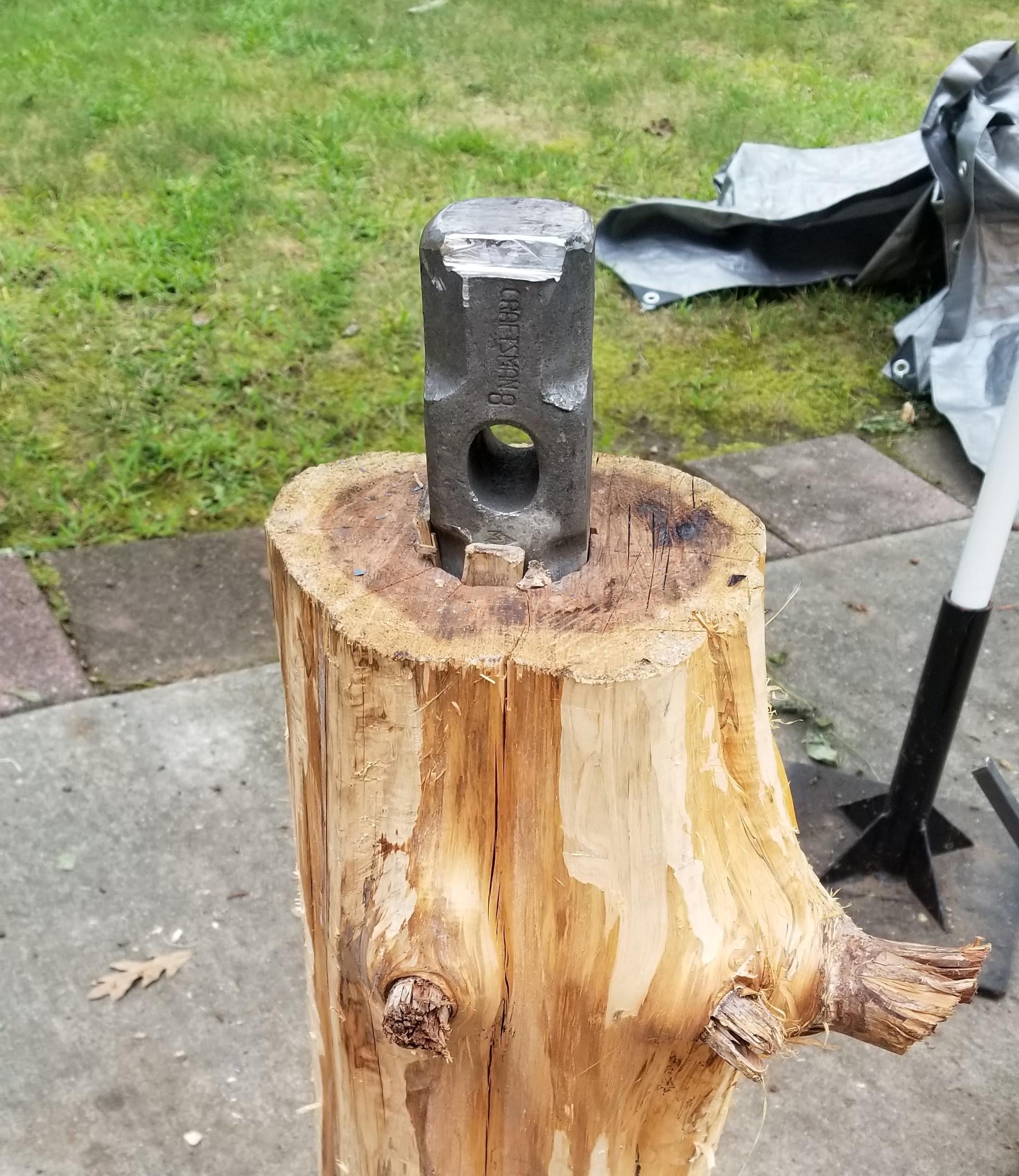
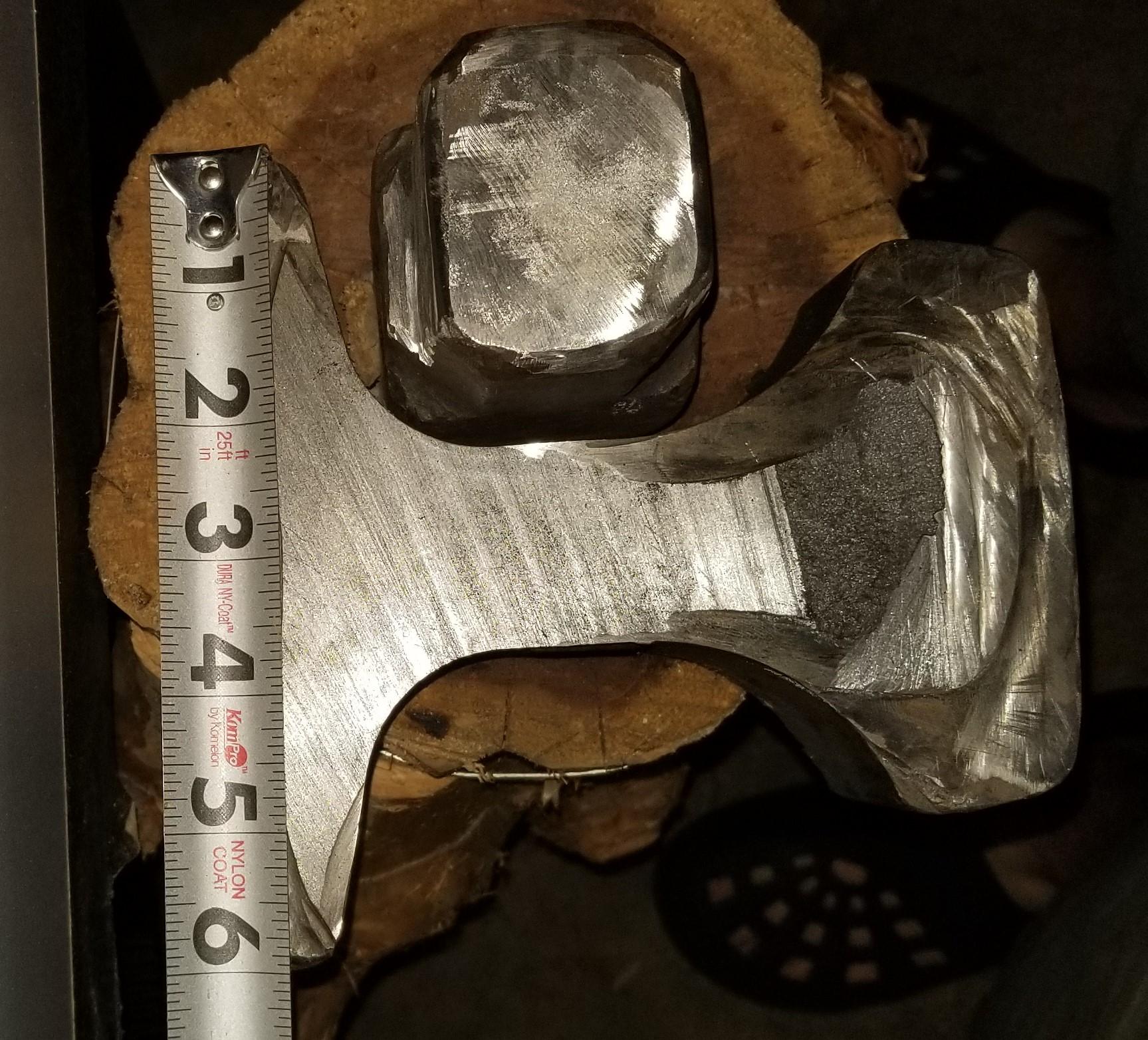
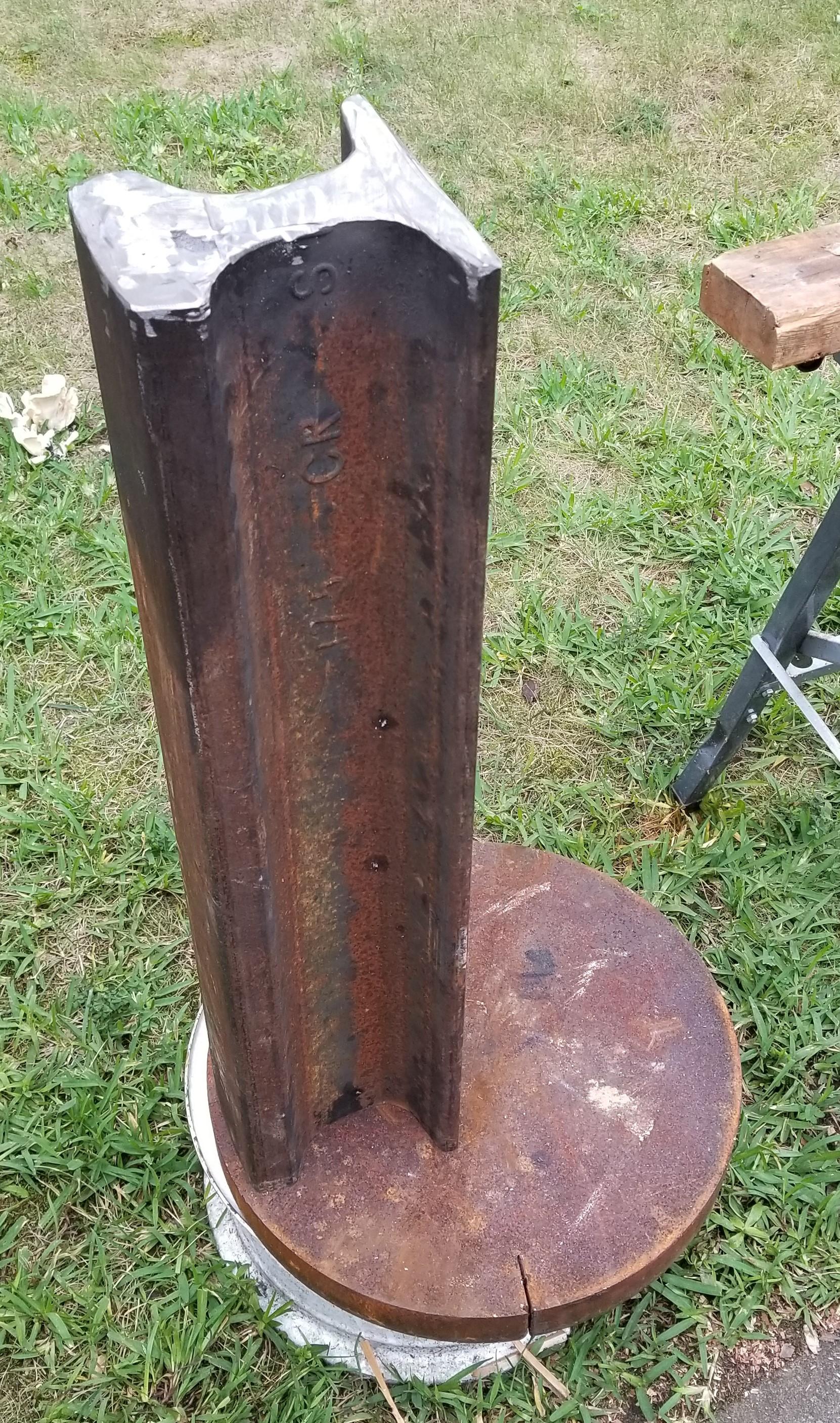
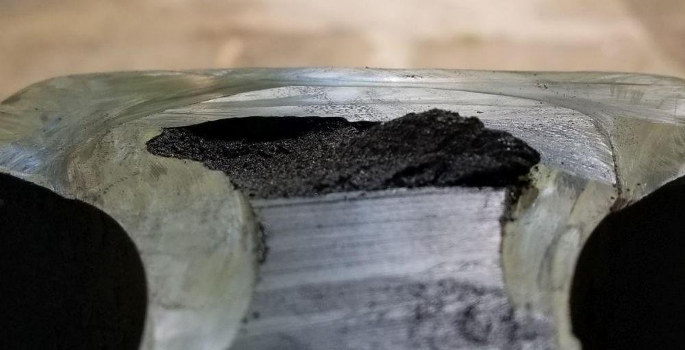
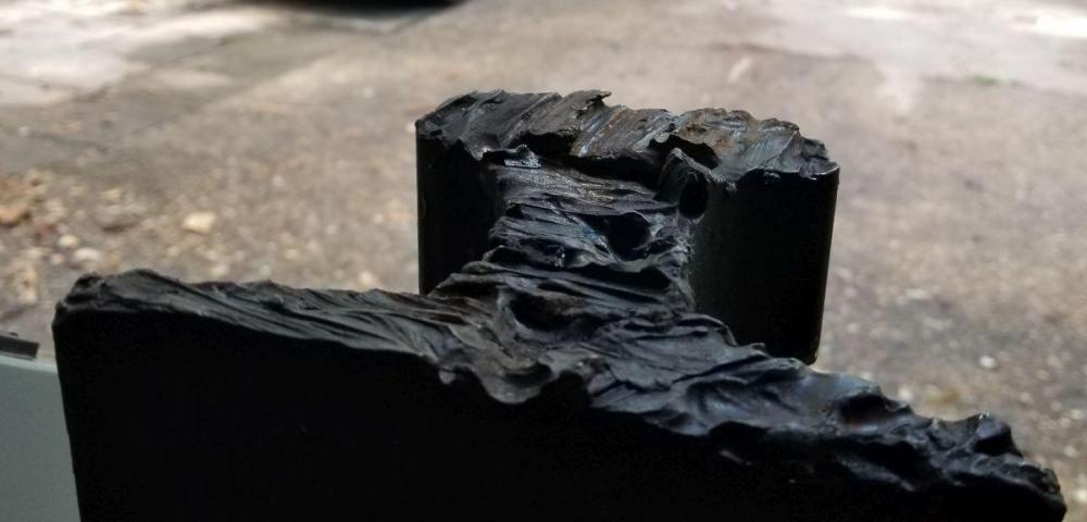
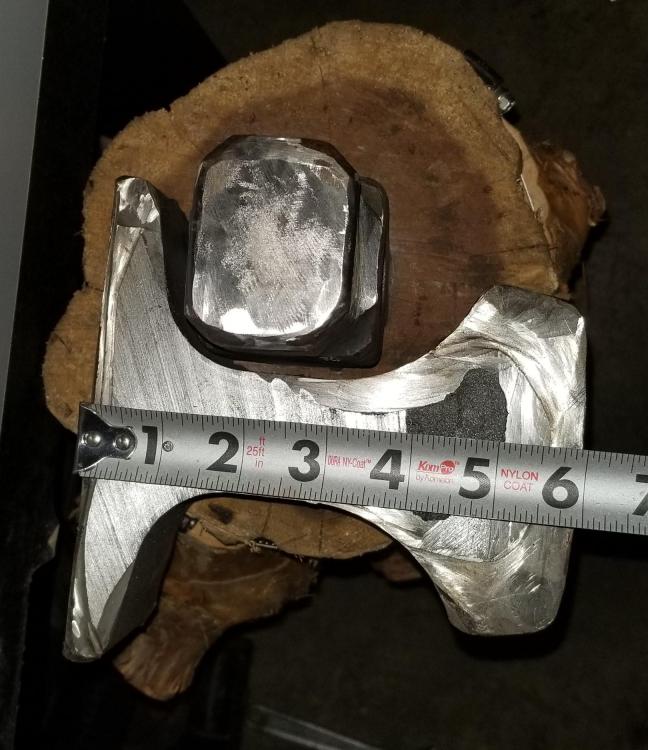
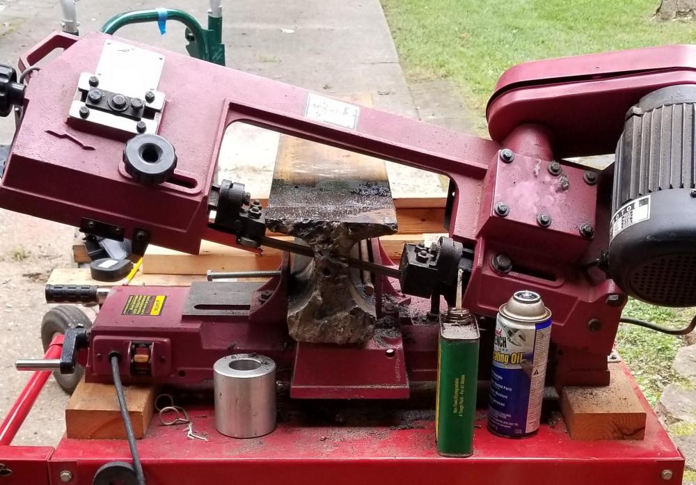
Thanks for the responses, all. Caotropheus, the sledge head's just a standard 8-pounder, can't say I've ever laid eyes on anything heavier in my neck of the woods (aside from a 10-pounder at the local hardware store). I'll sink the head a little deeper, but will leave the bottom part of the eye proud so as to have something to bear against for a retainer strap/bracket. Changing the depth too much at this point would also affect the overall height, so the bottom mods would also have to accommodate the change. Frosty, I'd cut the rail in the bandsaw that way specifically to avoid the hardened section. You can see in the picture of the slice (the one with the tape measure) where the bandsaw cut stopped. I was actually going to rotate it clockwise a bit to get an extra 3/4" or so of cut before grinding through the hardened areas and flipping it to finish the saw cut. Unfortunately soon after that picture was taken it started to rain, so I had to tear it all down and put things away. Given that this rail section feels like it's well in excess of 100 lbs, I didn't want to have to set it up in the saw again... getting everything in place and leveled was a MAJOR pain. When I had time again I went at it with the grinders around the rest of the section, and once I realized I didn't have another 7-inch cutoff disc on hand to finish the cut, I decided to try the fracture method. Took a few VERY solid swings to crack it off, and you can see the fracture area in the photo of the slice. Unfortunately fracture mechanics drive towards 45 degree breaks, so both pieces came away with both a divot and a lump that have to be dealt with. I filled the divot on the big rail as best I could with a lot of preheat and my cruddy 110V flux core welder and ground everything flat. I'm still deciding what to do with the slice- may end up as a bolster plate or the portable hole top, or give it to some kid in need of a striking surface (non-optimal though it may be). Couldn't be any worse than the sledghammer head, though I should probably test the veracity of that statement. Here's a photo of the flame-cut side. Turns out the guy at the scrapyard didn't realize that the nozzle on the cutting torch got swapped to a smaller size, so he had a heck of a time trying to get it severed from the larger rail... which is fairly evident here: Even for as thick as the rail is, I didn't want to affix it to the base plate without some additional bracing. In mechanical design that ends up being a pretty basic column, both with bending modes and a tendency to ring in a way that sucks out some of the hammer energy. By adding additional stiffening at irregular points along the column you can get rid of some of the harmonics and quiet down the structure when hit. It's part of the reason securing train rail to an L-shaped stump works reasonably well- it at least eliminates some of the freedom of motion laterally. They'd probably work even better if additional attachments could be added along the head of the rail, or barring that- just under the head into the webbing. Other handy add-ons notwithstanding, getting the rail near the edge of the base also makes it a little more accessible and allows working within the optimal height range. Having 1 foot on/1 foot off the baseplate would make things a little awkward. Next step? Get access to a beefy welder that can get reasonable penetration in this thickness of material. No amount of preheat was going to allow my 110V flux-core rig to do the job (believe me, I tried ).
-
A collection of improvised anvils
HojPoj replied to Charles R. Stevens's topic in Anvils, Swage Blocks, and Mandrels
Not sure if this is the right spot since I'm soliciting advice instead of showing off my improvised anvil... In my intro post I showed a huge counterweight that'll be my big anvil, but I'm working on covering the spectrum of configurations for non-London-pattern anvils. This is, in part, to have some items that I can take with me to show to friends and some students I mentor on a local robotics team, as well as having something more portable than the 387 lb Chunk-O-Steel. I've sunk a sledge head in to the end of a log (which works surprisingly well- especially when the log doesn't jump away). I just got some banding around the ends of the log today, but the picture below is before I did that. Planned improvements are a wider, heavier base so the whole thing doesn't move when struck, and a bar that goes through the eye to retain the head (the wedges seem to let go the moment a side load is applied to the 'anvil'). Now I'm working on my second piece, which is where I need some advice. At first, I thought the rail that I had picked up from the scrapyard was train rail, but when I look through all the references for rail dimensions it doesn't seem to match. Closest thing I can find is crane rail, which is still off by a little. In order to clean up the flame-cut end, I had to slice a bit of it off. Here's some pictures of the cross-section: I had this piece cut long knowing that the general guidance is to stand a rail on end to maximize the mass below the hammer. I have a 16.25" Diameter, 1.75" steel disc that appears to be waste from a flange making operation (the piercing cut starts on the inside and goes out to the circumerence). My plan was to stand the rail on end like so: ...and weld it to the base. I'd add a couple posts 120 degrees from this and some connecting struts to stiffen everything up and make a table/portable hole surface a little below the struck face of the anvil. Is affixing the rail to the plate like this a good idea, or should I cut some off and attach it to an L-shaped stump as others have? I'd picked this config just so I could roll it around like a heavy barrel, and given the masses involved I'm not too worried about it moving in use. Conversely, given that the web is so much thicker than standard rail, should I instead slice off a chunk to use in it's normal orientation? I don't exactly relish the thought of cutting it again, my 4x6 bandsaw has, ahem, *issues* finishing the job (not enough throat depth, and this thing's too xxxxxx heavy to manipulate), but I can manage between it and the grinders..


-
15KW Induction Forge Build - U.S. Solid - pic heavy
HojPoj replied to DRoberts's topic in Induction Heating, Oil forges, etc
Power Factor is generally a concern in applications with inductive loads (think motors and transformers). If the unit has a large transformer in it it could still show as an appreciable draw to the power company (though not necessarily reflected in your meter). A quick blurb on it can be found here: https://www.laurenselectric.com/home/business/understanding-power-factor/ -
What did you do in the shop today?
HojPoj replied to Mark Ling's topic in Blacksmithing, General Discussion
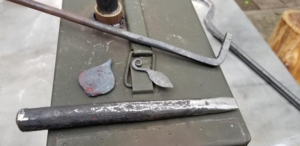
Being a beginner, I started a class this weekend with a local blacksmith. Made a couple leaves and I brought a piece of coil spring along to straighten out to made a chisel or punch. Today I tried practicing leaves again, but I isolated more material on the first one, as well as I did it on too- sharp a corner and ended up cracking it off. Tried again, this time it was too small, but still made it through. Didn't finish grinding the chisel til after, so didn't get to mark the veins. Also made an attempt at making a sharp corner by upsetting the bend. Managed to finally get the thicknesses reasonably matched, but ended up with some cold shuts on the inside of the elbow. Lastly, am working on some large tongs for a non-smithing application, and figured I would try drawing out the reins. My goodness did that turn out horribly.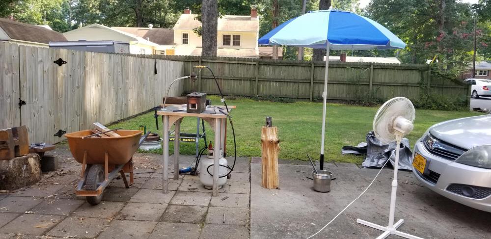

-
15KW Induction Forge Build - U.S. Solid - pic heavy
HojPoj replied to DRoberts's topic in Induction Heating, Oil forges, etc
Hilarious typo notwithstanding, it's a fair point. The barrier to its use, however, is that the power input requirements aren't universally available. Also, it is my understanding that the power factor for these things isn't real great, so extensive use at home might cause the power utility company to start looking at you a bit more closely. Customers with bad PF consumption sometimes get hit with surcharges (I've seen a few guys who weld a lot at home get hit with it). -
Composite (two-material) Punches, Chisels, slitters, etc.?
HojPoj replied to HojPoj's topic in Tools, general discussion
Excellent! Thanks for the confirmation everyone! Irondragon, I believe the majority of my stuff will likely to be made from coil springs or other less expensive alloys, it's just that if I need a tool that would significantly benefit from the heat toughness of one of the tool steels I wanted to be sure that such an arrangement would actually work out. -
Mikey, et tal, thanks for the responses- that clears it up. After noodling it over I could see where oddball pieces still wouldn't work with a brick pile forge if some of the dimensions were oversize. Beyond the use in specialized repeat/production work, perhaps a good way to spin the description would be that it's a forge you could 'clamp on' to a piece, rather than having to move the piece into a forge? (and thereby are free of the limitations of the forge opening size)
-
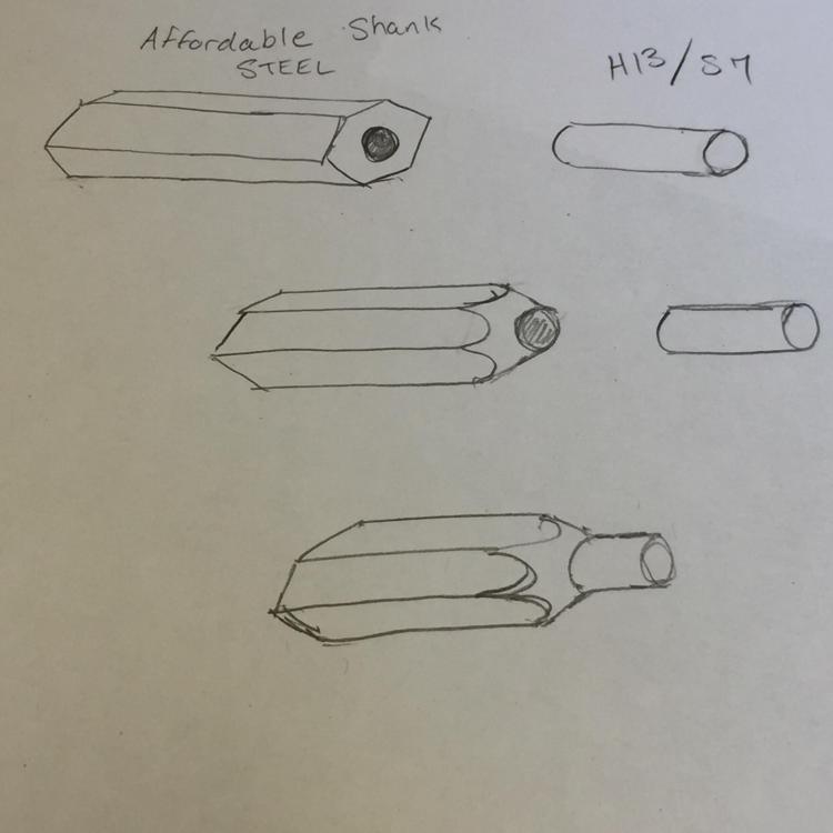
When looking for affordable bits of S7 and H13 materials for hotwork tools, there seems to be a greater availability of small rod pieces that are about 3" long, and sub-1" in diameter. If making smaller tooling whose business end isn't big, is there a way to put a larger shank on the tool steels and use them as though they were a monolithic tool? More to the point, if one could make a large shank (of 4140, for example) that could be shrunk-fit over a piece of tool steel, would such an arrangement hold up to occasional use? I'm not proposing that the tool steels be interchangeable, a proper shrink-fit would make it darn-near impossible to remove the inserted tool steel rod. I didn't bring up forge welding the pieces together since I've not seen any mentions of being able to do so with these series of steels (only really seen instances of adding a carbon steel cutting edge to implements like axes).
-
From what content I could find on that, most of the guys appeared to be using those short bridge anvils as a heavy sawhorse! Most of the content seemed to be them striking along the axis of the bit. Are there finishing steps along the way that would make the anvil the main reaction mass (i.e., striking perpendicular to the axis)?
-
I guess the fundamental question is "What is the use case for that type of design?" When you say 'dedicated', does that mean the inner chamber dimensions would be specifically sized/shaped for repeat/production work? And when you talk of interchangeable heads, does that imply you might have a flat base, and just the upper sections have special geometry?