tdriack
Members
-
Joined
-
Last visited
Everything posted by tdriack
-
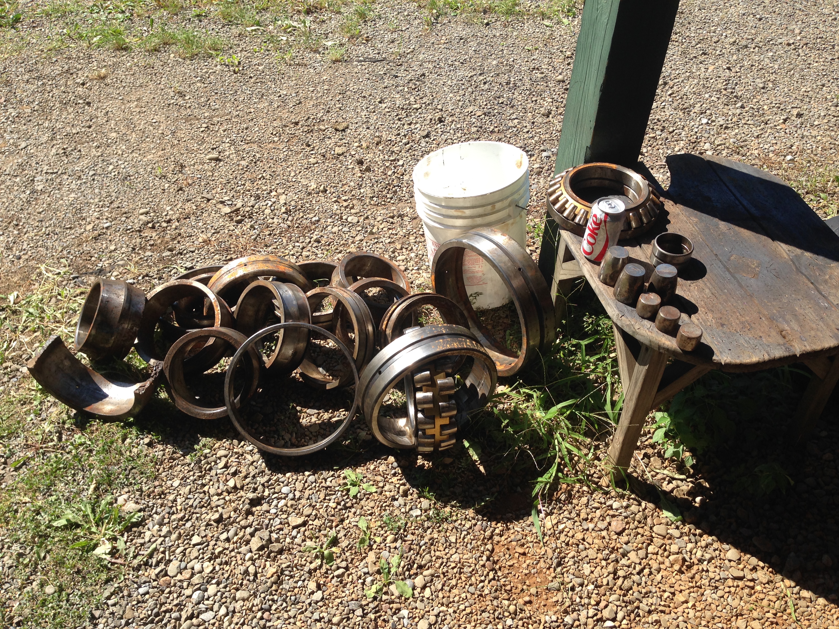
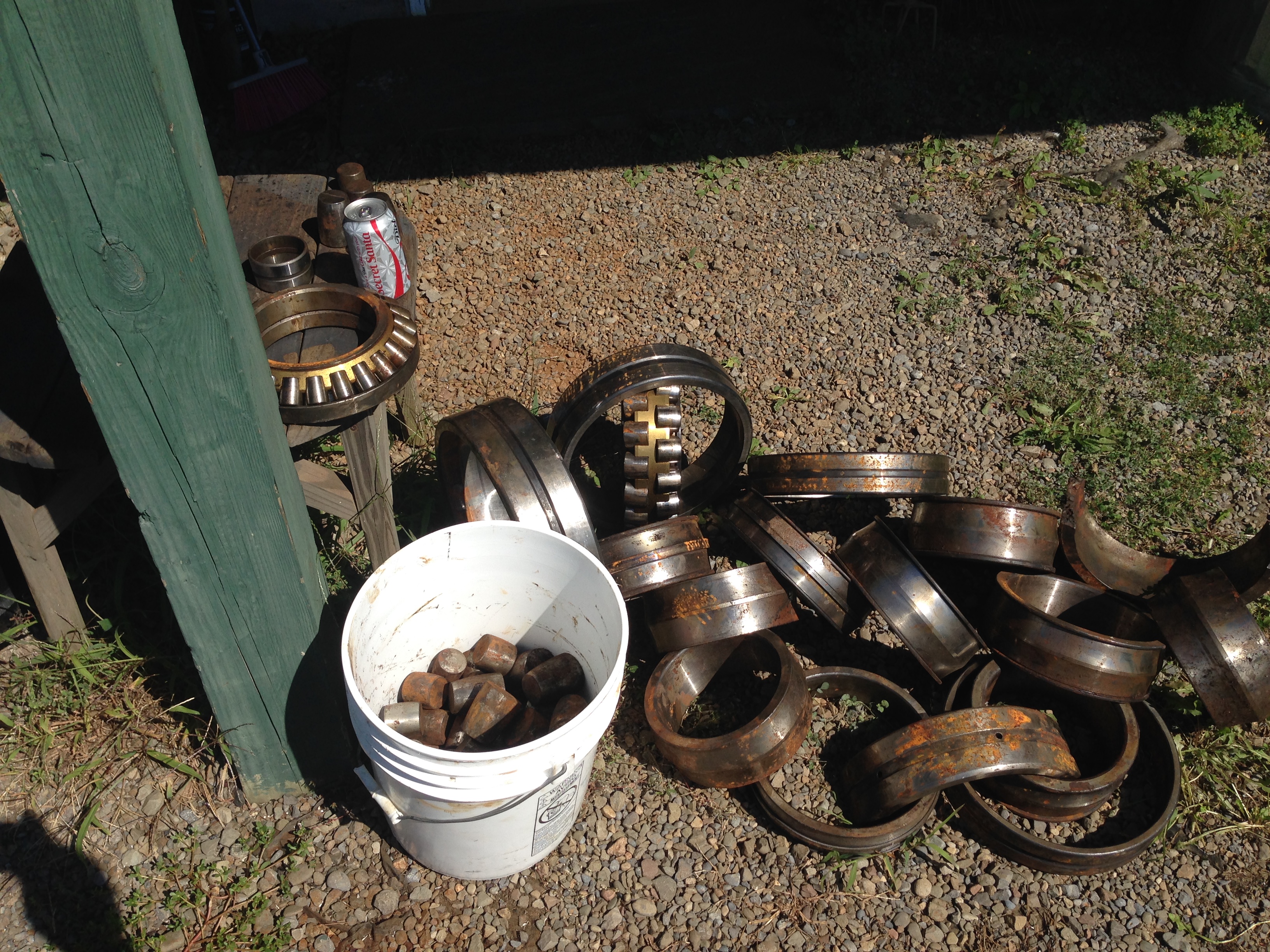
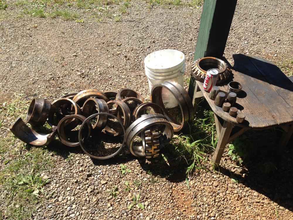
Hi Everyone! I came across a great find for free. Shipyard I was at was doing some spring cleaning - and was throwing out to scrap all the pictured bearing races and rollers. I haven't done any testing on the metal yet to confirm that it's 52100 steel, but I'm sure some is. It's all bearings from marine reduction gears. My initial plan was to use some of the small rollers to make some knife blades, and maybe make a hammer from a big conical roller as a keepsake, but I couldn't pass up the larger races and have a clean conscience lol. Note the soda can for sizing. Has anyone ever tried using similar metal for projects? I'd enjoy any comments or input.

-
Good Info Alan - I've never tried the quench idea. I do drill holes for centering on round bar stock. I see your point on cracks - but, my drill holes are very close together, and by the time I use the chisel to widen enough for a punch to fit - there are no folds that I can see - but I also always have my metal up at welding heat - so maybe that helps.
-
I start with a chisel as a cutter (to break through my drilled holes) - from both sides. Then, I use an old 3/8" dia punch hammer that the tip broke off on as a initial punch to flare the hole on each side (it adsorbs heat well and doesn't get stuck) - then move on to the drift. I might also add - be careful of pounding the tomahawk drift into the hardy hole - one time I hammered the drift thru my tomahawk head and wedged it into the hardy hole - hard - I'm betting there have been anvils that have cracked from mistakes like that - lol. Now I have a 4" dia spacer block -- 3" tall -- with a 1" dia hole in the center. I use that on top of my hardy hole now for extra height when drifting.
-
Latticino is giving you great info. Do you own a drill press? I've drifted pieces similar to yours by first drilling a row of 1/8" holes as close together as possible (shorter than the projected hole dia). The drilled holes act as a guide for your punches and drifts and also make the process much easier in my opinion. I also open the hole with the drift initially from both ends of the hole - looks like you hammered the drift straight through from one side only? I'd keep the metal hotter - do shorter drift attempts and reheat more frequently. Also - are you using a tomahawk drift?
-
-
-
Wow! That came out great! Great lines and finish detailing. I'm gonna pin it! Nice job!
-
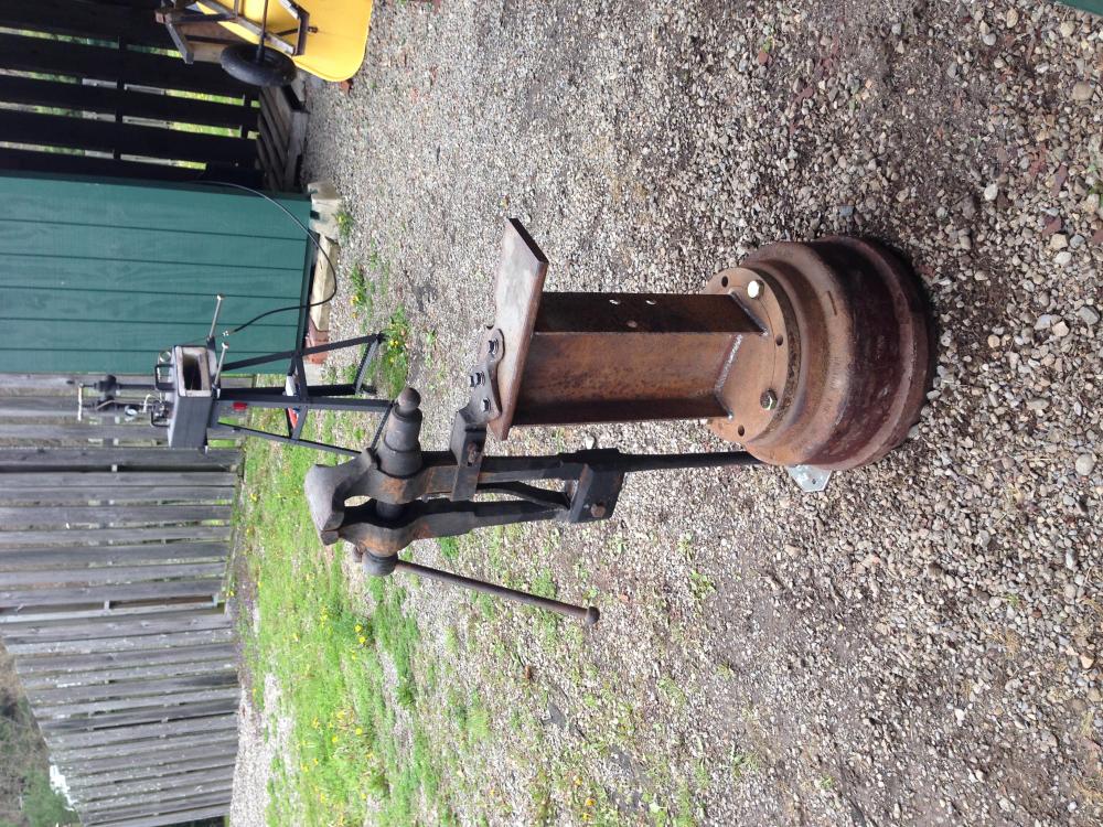
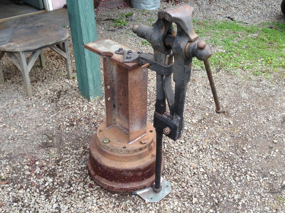
Here's my take on a post vise stand. School bus brake drum with a 1" thick pipe blank bolted on top. I-beam from a mobile home trailer frame and a 3/4" thick plate on top. The leg is mounted on a 3/8" plate that has a flange that was formed and welded to match the drum diameter. The plate is through bolted to the drum with three 1/2" bolts and there are two mounting holes for anchoring to the floor. There are two more plates through bolted on the back of the drum for anchoring to the floor similar to the one on the leg - but they weren't installed in this picture - so I could move the vise around in the driveway without digging a trench - lol. It's very heavy. On another side note- you can see my new gas forge stand in the background that I'm very happy with - Harbor freight very cheap - Just added the casters for moving.
-
I really like the dual foot pedal - looks handy. I'm in the process of gathering materials for my own press - so I have a question for you and others: you decided on the ram on the bottom instead of top - how does that design work for you? I have decided on a H style press - but I'm still trying to decide if I want the ram on top or bottom. Image searches seems to give a lot more top rams - so I'm really interested in your feedback on this - can you see your work as well as you would like and hold it steady as you press it with the ram moving upwards?
-
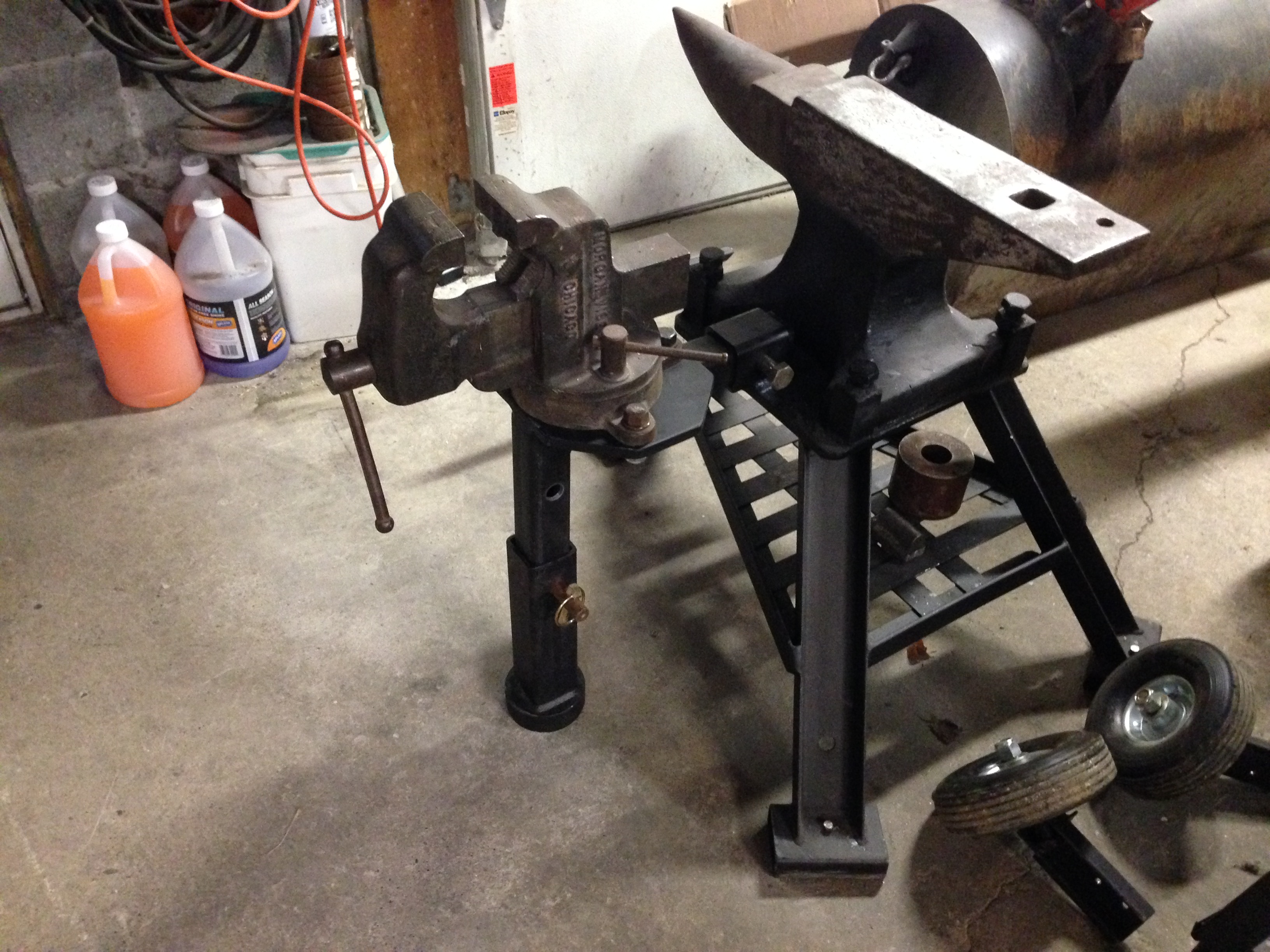
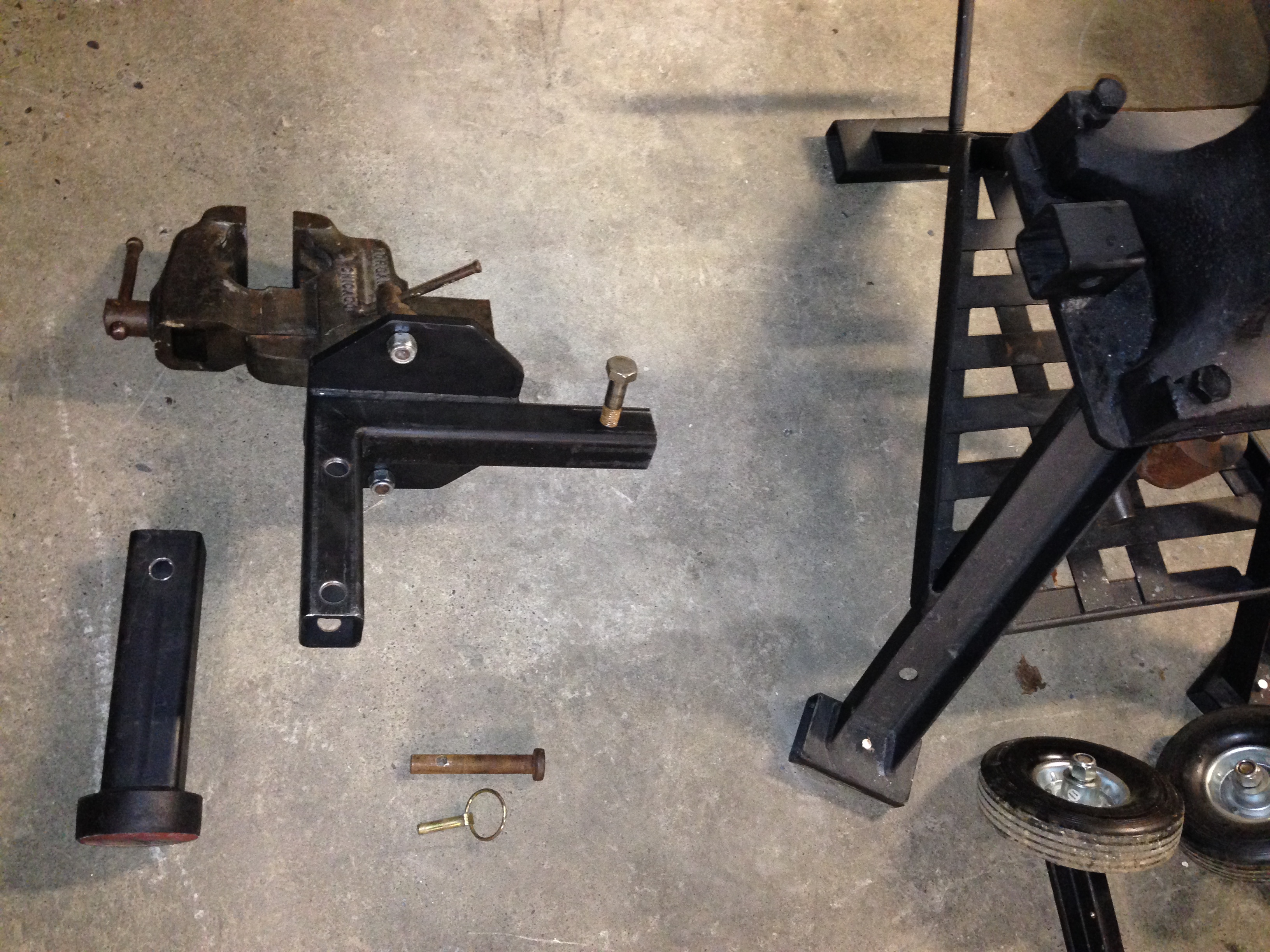
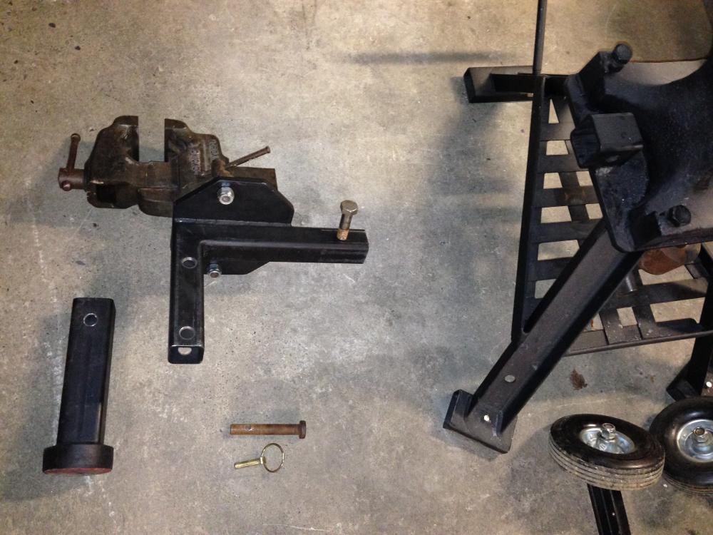
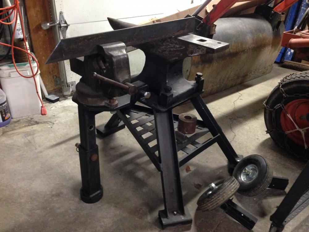
I just finished fabricating a removable anvil vise stand and wanted to share a few pics. I had a Morgan vise that I wasn't using - so I decided to put it to use as a removable side vise on my steel anvil stand. The stand is made from 2" and 2 1/2" steel tubing. It is set for height so that the jaws can be used to hold long items on the face of the anvil, or by itself for bending and twisting. I know this isn't as stout or rugged as my post vise - but for light work it is very handy. Removing it or installing it is very quick and the telescoping leg has a "up" position for storing it when it isn't on the anvil stand. It is very portable and as an added bonus --- it fits in the receiver hitch on my pickup truck also, making it very versatile for more than blacksmith work.

-
If you go with your own metal and welding you can save a lot. That being said, I would still have to say it will cost you at least 350-400$ being realistic. Wheels, motor, pulley sheaves, shaft, bearings, belt..... etc. If you decide to get rubber contact wheels, small diameter wheels and holder... etc --> easily double that. I see that ebay has new nylon wheels for way less than aluminum - But I'm skeptical on their long term use and on the belt tracking properly. All I can say is -- the 2x72 grinder is one of the most rewarding tools I have built - If I had known how useful it was --- for stuff beyond blacksmith and knife making -- like woodworking - I would have built mine much faster than I did. It's a very impressive tool!
-
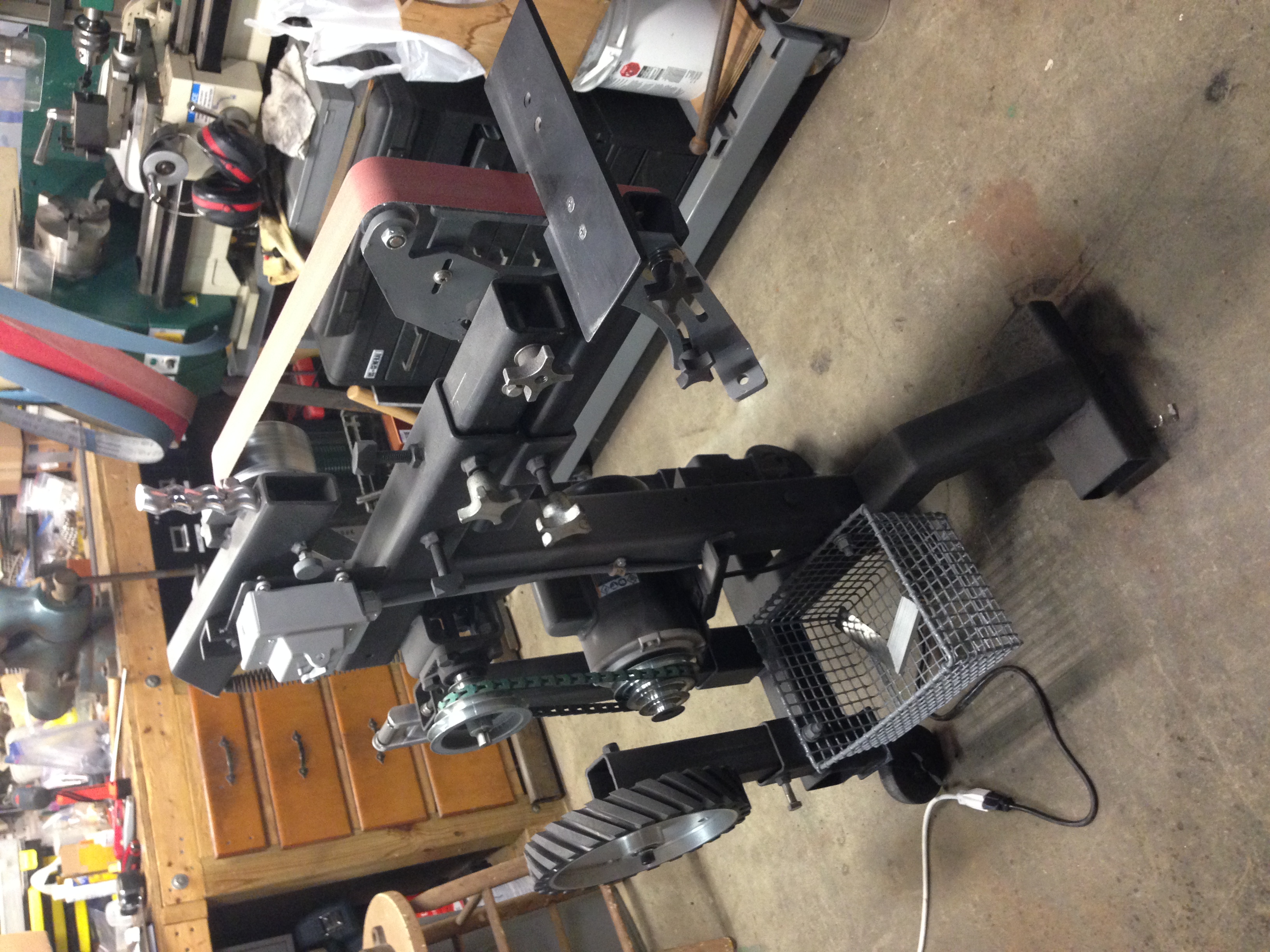
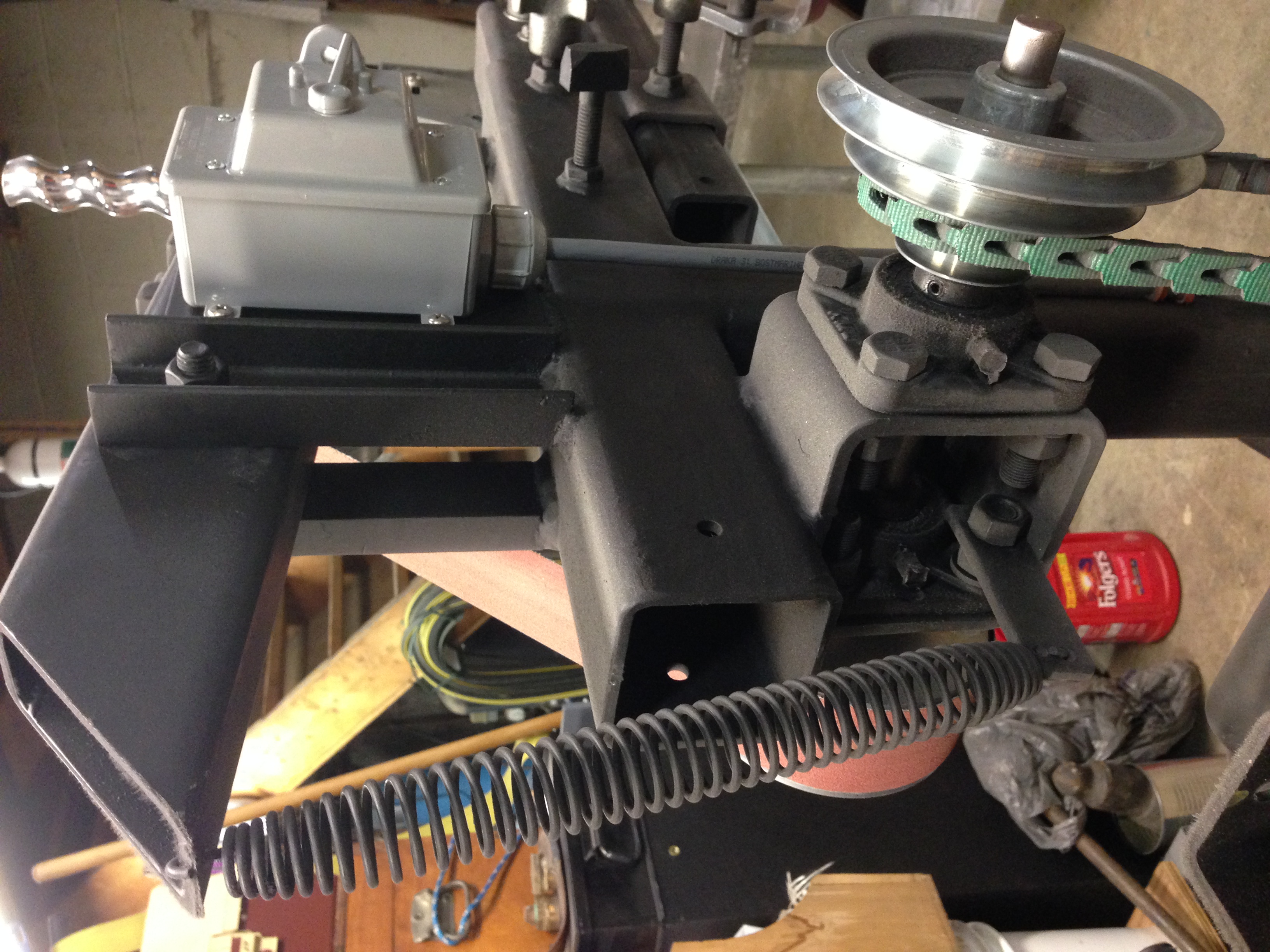
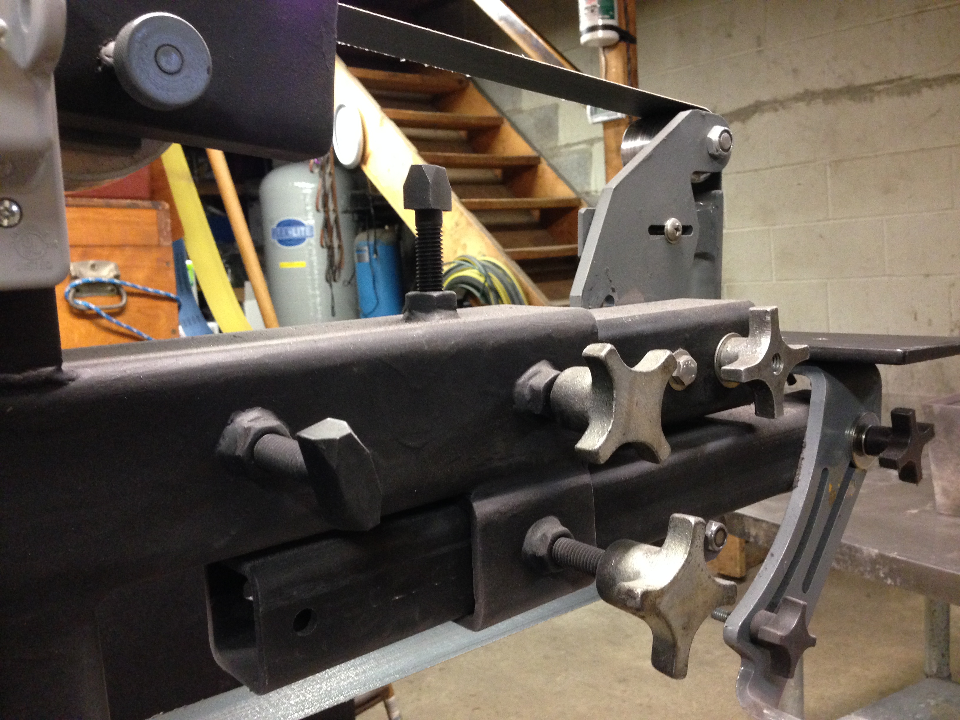
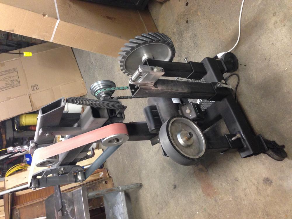
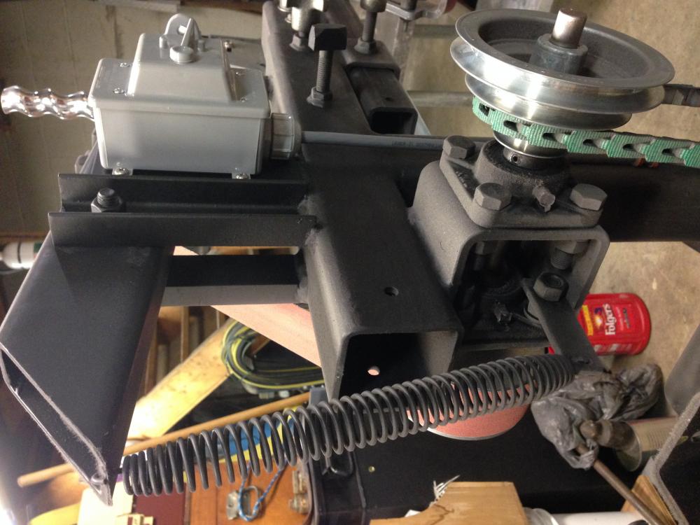
When I built the grinder, my primary concern was portability (since I'm sure you can see from the pics I'm a tad tight for room - lol). Without the casters locked movement is a problem - once they are locked and the wheels set straight and parallel to the front of the grinding wheels, movement hasn't been an issue. The small foot has two threaded adjustable feet that do a good job of anchoring that end to the concrete floor with friction - probably due to the weight of the grinder with all the attachments in place. It is heavy to move but manageable. My plan was if movement was a big issue, I'd make two wooden block feet - one for each wheel side that were just a little higher than the wheel height, and tip the grinder side to side so I could insert the wood blocks and lift the wheels off the floor - so far this hasn't been an issue. I did a lot of research and spent a ton of time pondering how I wanted to build this so I wouldn't need to do it twice (start to finish - probably a year of time on and off when I could). I read a lot of links on motors. In my opinion - the 1.5 hp motor works very well - 1 hp seemed too small from my research. My motor is a 1.5 hp continuous duty agricultural motor from Harbor Freight. I chose this motor over the Harbor Freight 2 hp motor - because the 2 hp wasn't rated for continuous duty and the reviews were poor. I know some guys will probably give me flack for this stores motor - but - I was trying to build the grinder on a budget - and that was the best option I could find at the time for the price. Now that I have swallowed the initial cost of building the grinder - if this motor fails - I'll aim to get a higher quality one as a replacement - but as of now - the motor has worked perfectly with no complaints to speak of. It is possible to bog down my grinder when I lean on a piece of work at the fastest pulley arrangement - but I have never stalled it. One day I had it plugged into a 15a outlet and was leaning on a piece of work hard enough to pop the breaker and had to reset it - it never stalled - if that is any indication of the 1.5 hp motor ability. I use a 20a receptacle for the machine now whenever possible and have had no issues since ( also note - the on/off switch is rated for 20a). Usually I use the second step / speed with very little bog down ever - and can remove enough metal to make me think in my head "slow down - don't wreck this project by removing too much!" In general, My mindset is not to bog down the machine - go a little slower if necessary and baby my new toy. Not to mention the cost of belts ...... I baby those too! The biggest limitation I placed on my motor choice was my current choice for shop power - it has to run on a 120v 15- 20 amp outlet for versatility in my shop - and if I ever want to take it on the road to a friends place. The 1.5 hp motor wired for 115v does this nicely. I guess if you have the ability to power a 2 hp motor with your shops circuitry go with a 2 hp - the price difference between a 1.5 and 2 isn't that big of a jump. I would have had to probably set my grinder up for 220v if I went with the 2 hp - and that would have put a real limitation on I where I could move it around and use it since my only shop receptacle for 220v is at my welder. I hope that helps....
-
I recently finished building my 2x72 belt grinder and wanted to share some pics. First off - this has to be the most rewarding tool I have ever built! The uses are endless - I wish I had made one numerous years ago. I used mainly scrap pieces of square tubing I had around in 3", 2 1/2", and 2" of various wall thickness to save on the cost. Due to that fact - The grinder is fairly stout and overbuilt a little - but it works like a dream. It uses a 1.5 hp motor wired for 110v. Four postions on the pulleys for various speeds. All of the wheels were purchased on Ebay - and although the price of everything did slowly sneak up on me - It was still way cheaper than buying a professionally built machine. The base of the stand is two pieces bolted - so it can be disassembled and transported in a car very easily. I have been doing some knife work with the grinder mostly since I finished it, and have several other attachments in the works and a few other rests I'm testing out. Any input you could give me on design ideas would be appreciated.


-
I have a steel stand. In my opinion - the angle iron is fairly stout in dimensions, I'd be more focused on the horizontal leg supports which appear to be flat bar. I my experiences, flat bar has a ton of flex. On soft ground, I bet the legs dig in and that absorbs the vibration and flex on the flat bar. On hard surfaces - the feet are probably flexing and moving a little- so not so much dampening. Putting pads under it will help I'm sure, but if you are willing to modify the stand a little - I'd try replacing the flat bar supports with angle iron and possibly making it into a shelf with either a solid piece of thin plate or grating to make it rigid. I also seem to remember someone mentioning putting a large magnet on the legs and vibration being reduced significantly???? But I never had to try that so i'm not sure if it works. Here's the link to my post - I don't have very much vibration problems. http://www.iforgeiron.com/topic/41426-new-steel-anvil-stand-with-removable-wheels/#comment-424162
-
Thanks for the info - I also heat my house with a rice coal stove. The price they have may be cheaper than the local coal yard - I'll have to check this years prices. The rice coal a lot of times is coated with oil to cut down on dust and is wet (I believe they wet it to add weight for the bags profit margin in sales lol) - so it will need to burn off all the contaminates at first.
-
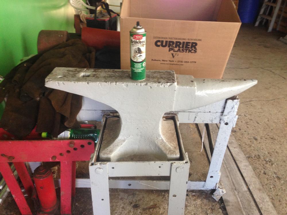
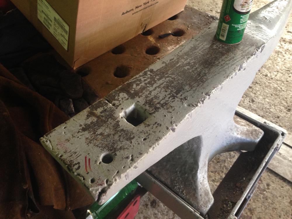
Discovered this anvil today in the welding shop for the tugboat company I work for. Just wanted to share the pic for the size of the anvil (look at the spray can on top). No visible markings due to the paint on it and I didn't have time to try to clean it and look further. Unfortunately it has a pretty serious torch cut in the face near the hardy - and even more unfortunately - it's not for sale -- yet...... I hammer tested it for ring with a small sledge - some ring near the horn - dull thud near the hardy and cut. It's got to be one of the biggest in the field anvils I've seen.
-
Damsutt I wish you the best of luck. I offered you a specific link that could possibly be helpful to you because it helped me. I had way too much coffee yesterday and was in an euphoric state when I thought it was a good idea to post a comment on this thread - looking at it today - I should have just kept clicking my mouse and moved on..... Sorry for the confusion there - I have no helpful input that can possibly solve your forge issues. Maybe your forge will work, maybe not...... I'd say you are in for some hardships with it. Frosty - I commend you for being patient and posting on new people's posts - you were very helpful to me. If you post here - and are new - be humble and be receptive to criticism - you are going to get it because you don't have it all figured out. Do your homework before you post or expect to be humbled. You can learn a lot from guys that have magnitudes of knowledge and first hand experience in trial and error.
-
I'm far from an expert - but I built my own forge. Goggle Zoeller Forge. That may not be the best design out there - but it works. Make a coffee can forge for starters if you are making a knife. Follow the information provided on his site. You need to make your forge much smaller and need multiple burners. Do some more research - you can do it. In my opinion - before you actually start heating metal and hammering - sit down and do a lot of reading and watch some youtube. You will be much less frustrated if you do that first.
-
I came across this picture online of a tire hammer build - It appears that the middle section of the anvil is a steel box with 2 pipe plugs in the sides. Looking for an opinion on this - why couldn't you make a tank and fill it with a liquid to gain anvil weight? Picture is pasted on a doc - I can't for the life of me find the original link - sorry..... Doc1.docx
-
Hi Phil! I've been quietly reading through a lot of information on power hammers for a while now, and after seeing your posts and pics - I am going to use this design style also. Very simple and effective. And also relatively inexpensive compared to other styles. Thanks for sharing your progress! I see that you have had some concerned input on the welded threaded rod - I think that is the weakest link possibly. The welded plate looks like 1/4" ? Seems less robust than the rest of the design - but that is only my opinion.... There are substantial forces on that joint. When I start building mine - I will "borrow" a lot of your design, but I'm thinking that pivot I will tackle differently. I will either make a fork end (3 sides of a piece of square tubing with a heavy threaded bushing welded on) - or I will go with a manufactured ball joint rod end either from automotive sources or from McMaster Carr. I will also use grade 8 bolts at all the pivot points. Thanks again for sharing - your input and research will save me countless hours of thinking and staring at prints and steel parts in my shop.
-
Hi Guys: I recently got my hands on a 3' long section of tugboat tow wire from my job. I want to try my hand at forge welding a short piece of a single strand into a pattern welded billet and make a small knife and also try etching. The wire certificate states the wire is 2" dia 6x37 EIP IWRC -- this scrap is non galvanized (unlike most tow wires). There is some surface rust - but also tar/grease that will burn out. So I get from research - EIP - Extra Improved Plow Steel IWRC - Independent Wire Rope Core EIP links i looked at show it to be somewhere between 1065 to 1085 steel. Is this worth a try to practice on? - or am I wasting my time and should look for an easier piece of steel ??
-
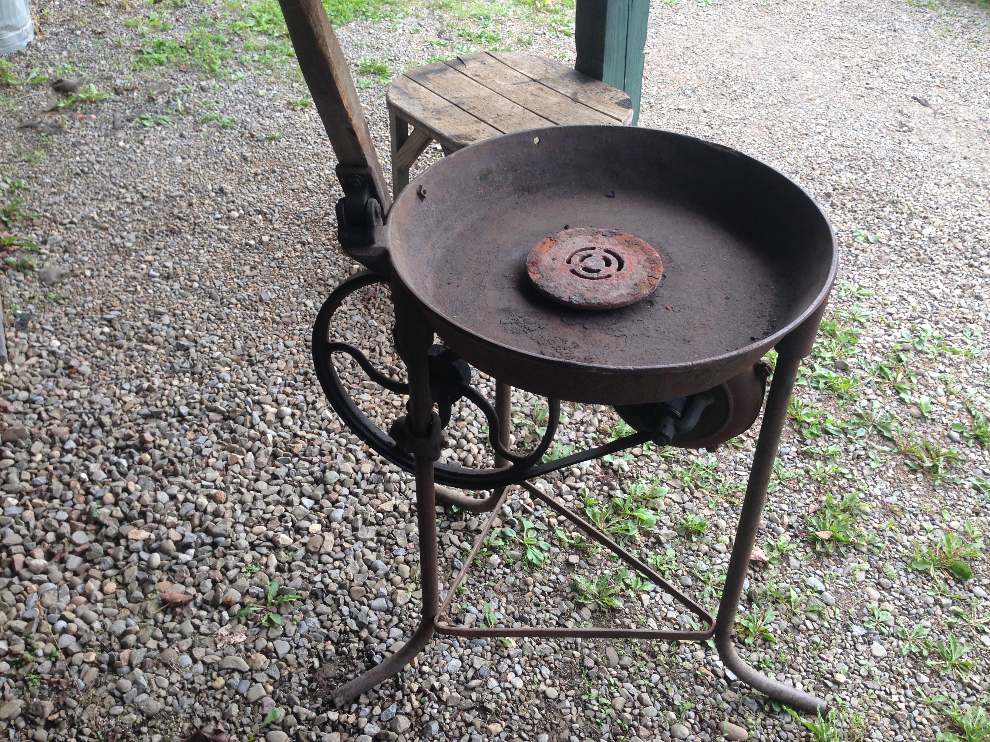
Thanks for all the input! I have cleaned the gear teeth and oiled it - and it is working much better now. It probably was sitting for a decade since it was last used and needed some exercise. Thanks for the input on the belt - it needs to be replaced since I started running it- there is definite dry rot. I initially had planned to get a appropriate sized automotive serpentine belt and use it inside out on the flat side - but I think getting a leather that can be laced and adjusted for length seems a much better idea.
-
Thanks Fatfudd! The 3 legs instead of 4 is what keeps throwing me off for an identification. I'm sure there was plenty of small modifications to models over the production years.
-
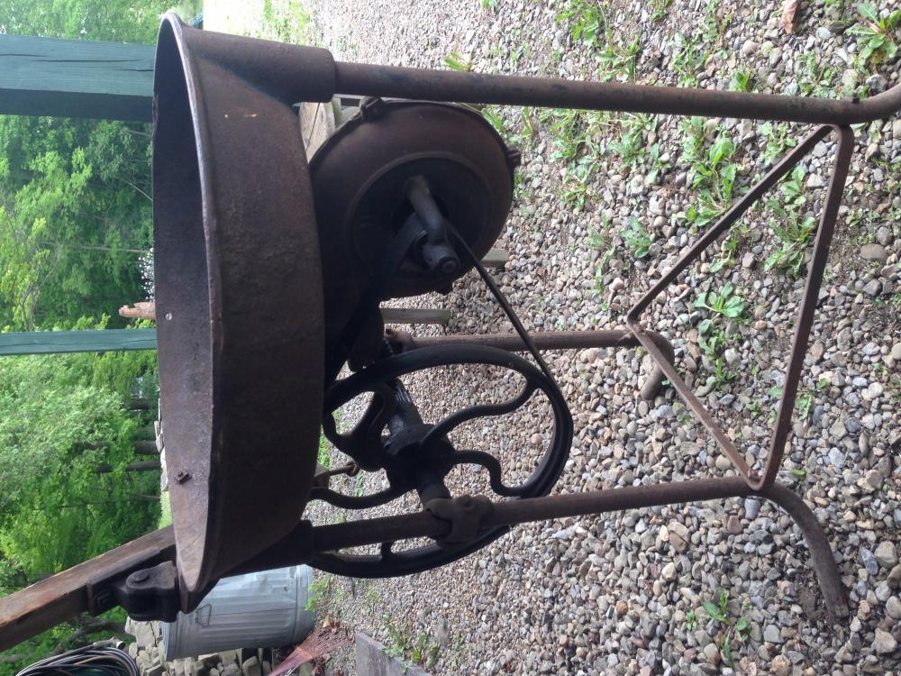
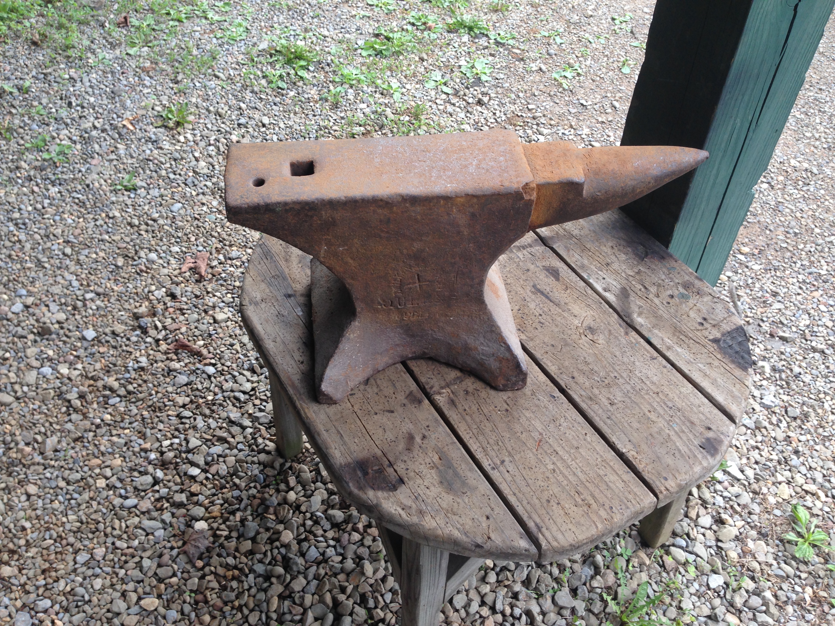
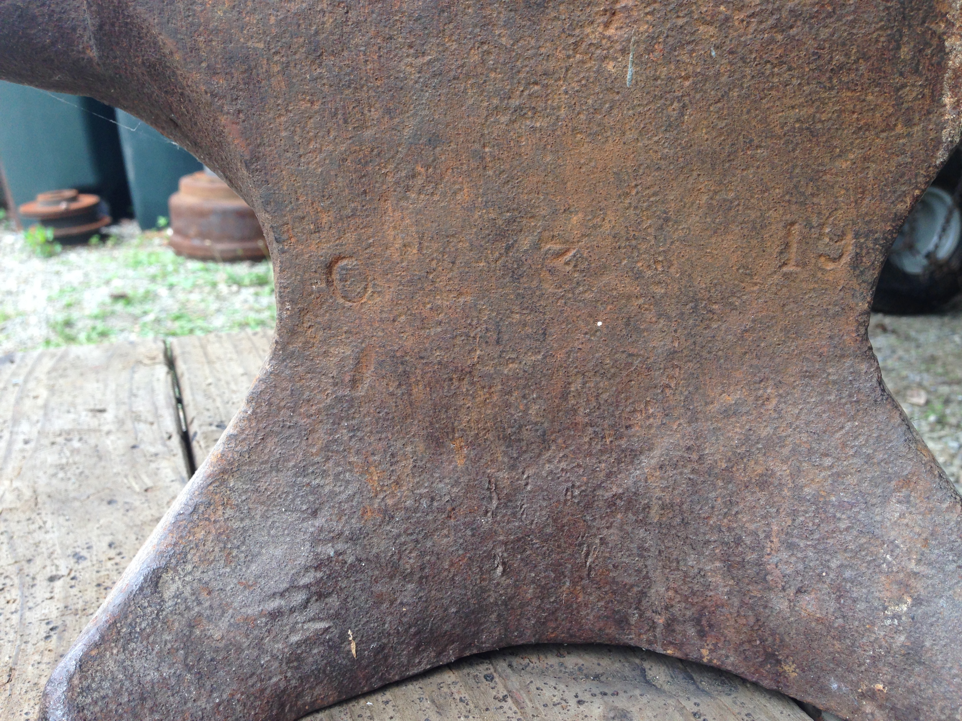
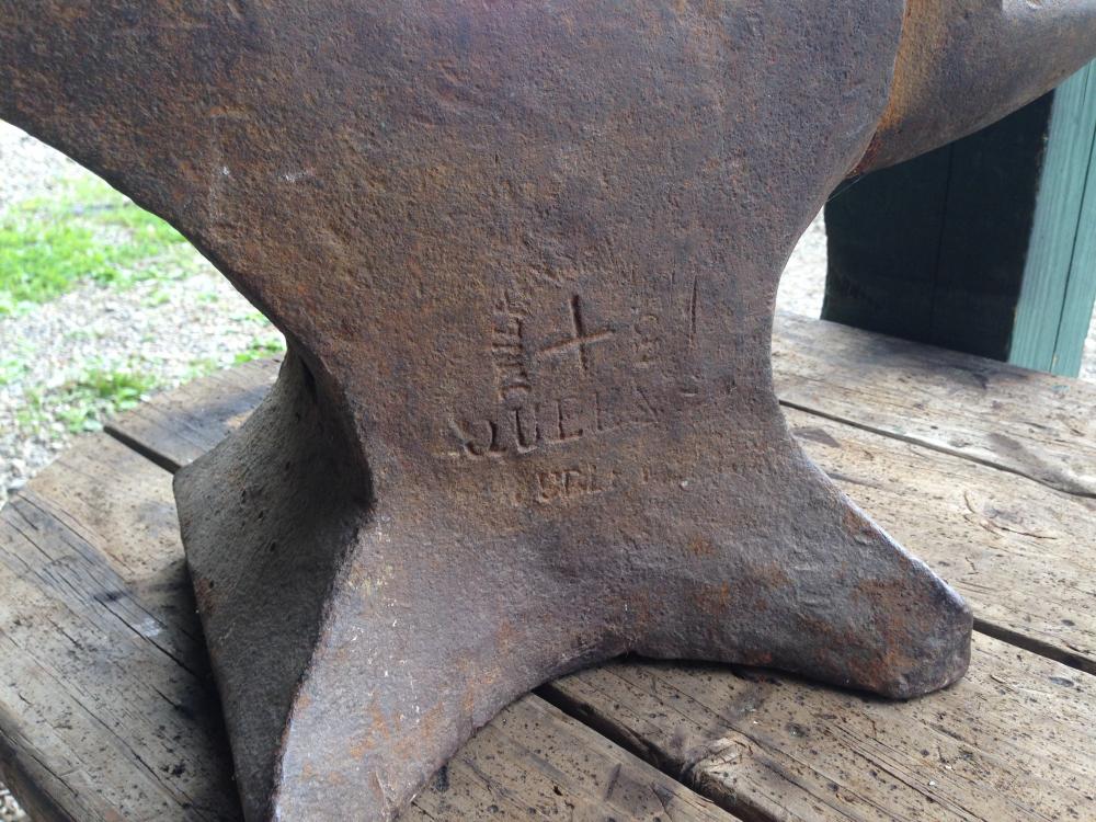
Just purchased this J Wilkinson Queens Dudley Anvil in a lot sale (I posted a pic of the coal forge looking for some help identifying in another thread). It's marked 0-3-19 --> I'm guessing - 94# Besides the chip in the face in the first pic - I'ts really in good shape imo. Ball bearing bounces very good on it. I've seen many pictures of these anvils with the tops warped from use - this one is fairly flat. For my area this seems to be a rare anvil and I'm glad to have acquired it. Its smaller than a lot Queens Dudleys I've seen posted, and will be portable and handy to have. I'm going to go with a wooden 2x12 layered stand for this anvil and will post a pic after I finish it up.


-
Good Day All: I just purchased a lot of blacksmithing items very cheap! Coal forge, Queens Dudley anvil, 8 pairs of tongs, and 5 hammers - all for 300$ ! I've done some research online for the coal forge - but can't identify it's maker 100% (there are no markings on it anywhere). Can someone help me with their expertise in identifying it? It needs a little work - but should work fine. Belt is in bad shape, and I need to look over the gearing/ pinion for the blower drive - it's worn and tries to skip occasionally. I'll also post a pic of the anvil in the anvil section - it's in good overall shape.