WoodnMetalGuy
-
Posts
88 -
Joined
-
Last visited
Content Type
Profiles
Forums
Articles
Gallery
Downloads
Events
Everything posted by WoodnMetalGuy
-
I set up mine to be at belly button height. Just seemed right to me. -- Dave
-
Sounds like that's talking about adjusting the belt tracking... -- Dave
-
I've used them in boatbuilding, mixed with epoxy to produce an easily sanded filler, not used for structural purposes. Hadn't thought about putting them in refractory... -- Dave
-
Thanks, Vaughn, I'm looking forward to trying this. I have some lead that I will probably use for two-sided stuff. And have some brass around, too. I'm thinking either of those would also work. -- Dave
-
Had not heard of these before, so I learned something new today. Here's a link to setting one up for anyone else who might not know what a pitch bowl is: http://www.alberic.net/Student_Home/Handout_Archive/files/PitchBowls V1-Web.pdf Do I understand this correctly - that the idea with the copper that it's softer than the steel and so the ridges on the reverse side indent the copper vs. the copper mushing down the ridges? -- Dave Another thing that works is using a laser printer - when you put the paper face down in contact with your work and heat the back of the paper with an iron, the toner will transfer to your work. I haven't ever tried that on metal, but it works on wood. Remember you need to print your design in reverse if you have lettering or other non-symmetric items. -- Dave
-

20 pound propane tank forge in progress
WoodnMetalGuy replied to Irondragon Forge ClayWorks's topic in Gas Forges
OK, could not tell from the photo. It looked to me like it was still pointing directly into the middle vs. coming in at a tangent. Either way I'm not sure how much that matters. I think the key to heating is how much time the flame spends in the forge and how complete the burn is. Earlier today I ran across some interesting information in this document: http://azblacksmiths.org/wp-content/uploads/2016/04/Forge-build.pdf. Here's a quote from that: -- Dave -
Yes, when I get my grinder built, I'm planning to just aim the sparks into a metal trash can or bin and contain most of the grit that way, as it doesn't float around in the air, like smoke or wood dust does. Maybe handling grinding particles that way and using a fume extractor for airborne smoke would be a good hybrid approach. -- Dave
-
20 pound propane tank forge in progress
WoodnMetalGuy replied to Irondragon Forge ClayWorks's topic in Gas Forges
I think Wayne was suggesting not that you rotate the forge body, but that you change the way the tube enters so that it's more tangental to the center space, rather than pointing across the middle of it. However, in reading some material Ron Reil has on his website, he doesn't seem to totally agree with that philosophy, and even likes having a hot spot in there, so he can concentrate heat on his stock where he wants it... -- Dave -
Good story, thanks! I especially like the photo sequence from rough to finished, and your idea of making your own handle material. Did you use an epoxy resin for that, or something else? -- Dave
-
Forge lining question, ceramic fiber board?
WoodnMetalGuy replied to redbate's topic in Insulation and Refractories
Redbate - As I understand it, if you coat with the rigidizer, you would still want to put on a layer of refractory (like satanite) to toughen up the interior and protect from dings from your work. However, I believe you can skip the rigidizer and just use satanite for both purposes (encapsulation and tough coating). That's where I am on my forge build and is the plan I'm going to follow. If someone thinks different, now would be a good time to chime in. Regarding the fiber board on the interior, I don't think you need that. Just the kaowool lined with satanite. However, I will be using a piece of ceramic fiber board as a movable back wall in my tunnel-type forge to allow me to reduce the chamber volume for small work. And I expect that a smaller volume will be the general case. I have a piece of kiln shelf for the floor, but I expect fire brick will work for you there. -- Dave -
Finished new tire hammer
WoodnMetalGuy replied to canada goose's topic in Power Hammers, Treadle Hammers, Olivers
Looks like it goes well. It will be fun to see it with some hot metal in there vs. the wooden board! -- Dave -
Forging large Circles HELP
WoodnMetalGuy replied to Hephaestus Smith's topic in Blacksmithing, General Discussion
Did you mean 1/2" square stock? So you want to make a 4 foot ring out of 1/2" square stock? Probably in industry it would be done on a ring roller, two rolls on the bottom and an adjustable third one - a triangle configuration. Lowering the third roller gives a tighter radius. And I have seen a similar configuration of round bars on a fly press to bend the stock bit by bit (generally cold) until the full circle is formed. Maybe you could do something similar to that with a couple blocks and a hammer and a template to judge whether you're on track or not? -- Dave -
Two great minds! I'm glad we came up with the same answer! -- Dave
-
I think you can just do a volume calculation and be pretty close. You currently have 1 x .75 x 6.5 = 4.875 cubic inches. So your target is .5 x 1 x ? = 4.875, so your answer is 4.875 / .5 = 9.75 inches long. Just doing this in your head you could see that the current cross section is .75 sq inches, and you're going for .5 sq inches, so based on the cross section being 2/3 as much, the length will be 3/2 or 1.5 as much. -- Dave
-
Sorry, I'm not familiar with the internals of this vise, but since the handle seems to be unscrewing when you try to open the vice, part of the mechanism that secures the jaw to the screw must be broken or missing. If you start taking it apart it will probably become obvious at some point... -- Dave
-
Frosty - yes, good point. I was trying to explain the difference between compression and flare fittings, and am sorry if I confused the issue! -- Dave
-
No, that's a compression fitting. What you want to use to hook up to copper tube is a flare fitting of the appropriate size for the tube. Here's an example of a flare fitting: https://www.lowes.com/pd/BrassCraft-1-2-in-x-1-2-in-Threaded-Flare-x-MIP-Adapter-Adapter-Fitting/50380844 You need a flare nut to go with that. To make the connection, you slide the nut on the tube, then use a flaring tool to flare the end of the tube, then screw the nut onto the fiting, trapping the tube in between. -- Dave
-
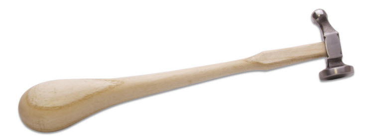
Didn't know what those looked like, but easily found some images. Why do they have that large bulb on the handle? Is it a syle thing handed down through the years or does it serve some functional purpose? -- Dave
-
I like those hammer heads, and I think you could enhance the overall look of the tool by just doing a little additional shaping of the handles along the line of the photo below. I don't think it would take much to make them look a little more graceful. A spokeshave would be a great tool to use for that. -- Dave

-
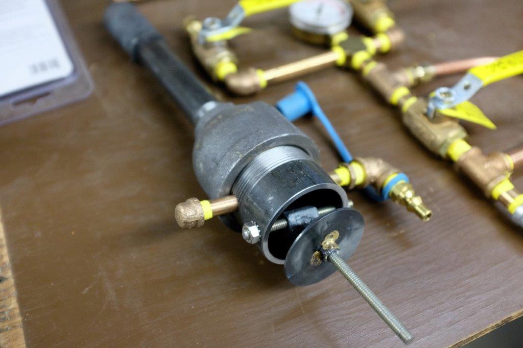
Here's what I've got for a choke plate. I'll be trimming the threaded rod that the plate is on, don't need it so long. One weld to attach the threaded rod to the side of the coupling nut, and a braze to attach the nut to the choke plate, other than that it all threads together. -- Dave

-
Here's what you want: https://www.amazon.com/Wiring-Simplified-Based-National-Electrical/dp/097929455X You may be able to find this at a Menards or Home Depot, also. Good book that shows you exactly how to hook up your plug and switch, etc. Geared to beginners. If you need to restrict airflow you could partially block the input of your blower. Some little bit of sheet metal on a screw that you can pivot over the intake. The fan in your photo looks like a little squirrel cage fan, which won't be able to build much pressure. If you need more air you may want to look for a radial vane fan like the traditional hand-cranked coal forge blowers. Or like what is used in shop vacs. Here's an example of a radial vane fan. Not that you'd want to use this one in particular, but you can see how the fan vanes are differently arranged: http://www.surpluscenter.com/Electrical/Blowers-Fans/DC-Centrifugal-Blowers/12-VDC-DRAFT-INDUCTION-BLOWER-16-1390.axd -- Dave
-
If that's a 12V motor, you won't be able to plug it into the wall, which is 120V. And if you meant 120V, you still won't be able to plug into household power if it's three-phase. Sorry, I don't know how you'd run one of those... -- Dave
-
Trying to figure belt speed
WoodnMetalGuy replied to John in Oly, WA's topic in Grinders, Sanders, etc
Nice, thanks for that explanation. I can see the hinge now. And I really like the cast brass knobs - I hadn't picked up on that detail before! -- Dave -
Trying to figure belt speed
WoodnMetalGuy replied to John in Oly, WA's topic in Grinders, Sanders, etc
John - Looks nice - I've been contemplating building one lately. Where did you source the wheels? And is there a tracking adjustment somewhere? I couldn't spot it in the photos. Thanks - Dave -
And I bet it wouldn't be too bad to rework the bottom to shorten it up by a few inches? -- Dave