Another FrankenBurner
-
Posts
619 -
Joined
-
Last visited
Content Type
Profiles
Forums
Articles
Gallery
Downloads
Events
Everything posted by Another FrankenBurner
-
 We attempted our first pour. We suspect we were pulling too deep of a vacuum and cracked the investment. It is amazing how much aluminum can be pulled through a crack. We shut off the vacuum and poured to the top. It ended up hideous but we managed to pull a working burner out of it. We have built a bleeder to control the amount of vacuum for the next attempt. I also printed a 3/8 version and a 3/4 version. The 3/8 version has a beautiful flame with the 023 tip and a stepped nozzle. The 3/4 version has not been run yet as I have to get bigger tips. I am curious which tip it will end up needing.
 -
I am looking for a castable refractory with a smoother consistency than kast o lite which can withstand the heat. I am experimenting with ribbon burners. I have looked around but most refractory talk is about it's insulative quality or how to mix it. Has anyone tried sifting kast o lite?
-
If you induce that much extra, so long as proper mixing is happening, it's time for a bigger jet. There is a reason that Burners 101 is at 59 pages. Welcome to the club. Hi, my name is Curtis, and I have a problem. You could try the split bushing method of holding the 1/4 inch accelerator. It seems to work well for the burners which use it.
-
Naturally Aspirated Ribbon Burner. Photo heavy.
Another FrankenBurner replied to Frosty's topic in Ribbon Burners
No problem, it's the least I could do after throwing the confusion grenade in there. I think your thoughts on range shift are probably accurate. I am not experienced with the AMAL, other than a little research. There is a possibility that the bigger jet is too big and the flame can not be tuned out of rich. If you can get to an oxidizing flame with the smaller jet, it is worth trying the larger jet. It depends on your goal. An oxidizing flame is not useful to me, I would rather have a larger jet for it's benefits. -
Naturally Aspirated Ribbon Burner. Photo heavy.
Another FrankenBurner replied to Frosty's topic in Ribbon Burners
I am that guy, yep. Though, in regards to me being a good team member, did anyone read what I posted? I just did and it made me laugh. More fuel out of a smaller jet? What I meant to say: I don't think that a smaller jet induces significantly more/less air at a given pressure. By going to a larger jet, the air induced will be similar while the fuel will be increased. If you have an oxidizing flame, this is good. If you have a reducing flame, you want less fuel for the volume of air which means a smaller jet may be good. I think of it as the jet changing volume of fuel, not volume of air. Nozzle/outlet, mix tube length, inlet geometry, back pressure, choke position, jet position, and fuel pressure can all change air volume. -
Naturally Aspirated Ribbon Burner. Photo heavy.
Another FrankenBurner replied to Frosty's topic in Ribbon Burners
I don't believe a smaller jet induces more or less air at a given pressure. It adds more fuel. Where you already have possibly rich flames, I suspect a larger jet will make the flame more rich. Worth trying though. -
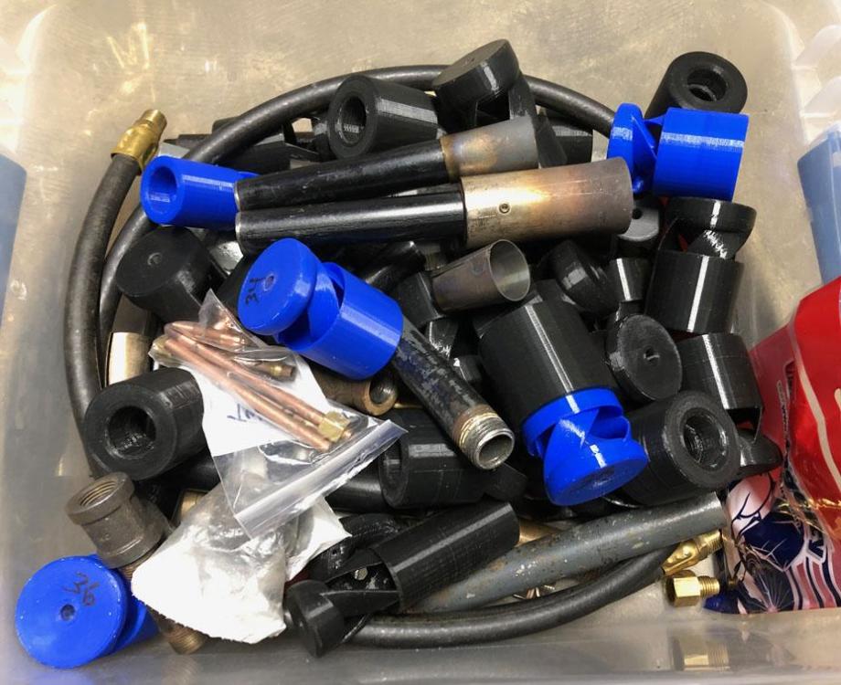
I just recently realized I can display images smaller in the post. I am leaving them a bit larger now so they can be clicked on for a better view when desired. Big day today. Finished the vacuum table. Ugly and functional. Tested different investments. Also tested vacuum chamber use for bubble removal. These prints are mostly hollow, it is possible that with a vacuum chamber, we could pull the air out of the void and have investment enter. We tested today by pulling a deep vacuum on a test piece. We also worked on a better nozzle for the 3/8 version. A piece of 1/2 inch pipe was bored to slip over 3/8 mix tube. A piece of 3/4 pipe was bored to press fit the 1/2 inch step. It was a quick and dirty job. We will build some better ones when we get some stainless. We also mostly completed the new big furnace. Now we need to rebuild the little furnace. I built this guy a while back. I have a picture of it on page 2 (third image). I needed a bigger nozzle and just happened to have a Zoeller flare for a 3/4 inch burner so I made a step out of 3/4 inch pipe. It is the nozzle I always select now. I am wanting to experiment more with nozzles. It has been read. Thank you for the information. I read everything that goes into Burners 101, Forges 101, and the NARB thread. My accelerator assemblies are made from left over 1/4 inch pilot tube pieces. It is a good match for the tip. I turn down the mig tips and braze them. The more common pilot tube assemblies are a 3/16 tube(left in the image). I have lots of left over pieces. I measured an ID of 0.128" and plan on swaging an end to braze in capillary tube. Hopefully it performs well.

-
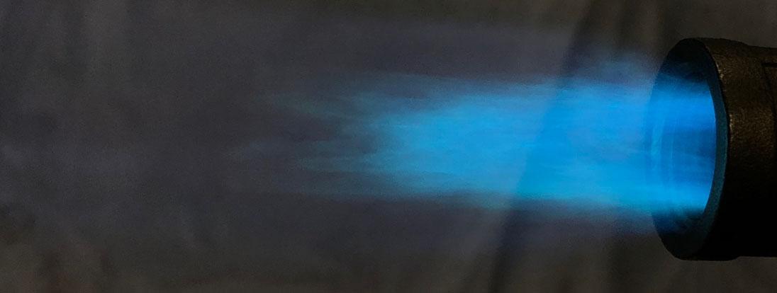
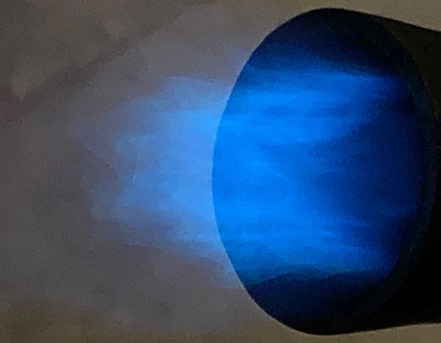
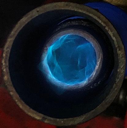
Question for Mikey, what lighting is best when evaluating these flames? I am usually in dim lighting when testing as it highlights the zones. Today the sun came out, I was in shaded but brighter sun light and the flame was purple in that lighting. Also, you like the 3/8 burners. I have scaled down v41 to a 3/8 mix tube v42. I don't have the proper mix tubes or nozzles to play with in this size yet. All I have are a 4 inch nipple and a 1/2 inch x 3/8 inch threaded reducer as a nozzle. It runs rich with the 023 but I suspect having the proper sliding nozzle will correct that

-
It's a good name. I was kidding around.
-
Oh that sounds fancy. I don't think it should have a cool name, I might try to take myself seriously. Plus Mikey has the Vortex burner.
-
But the gizmo doesn't flame. Twisted sucking gizmo? We probably should not go down that line. When the diameter was smaller and the ribs longer, someone in my family called it a twirly burner. It's not so twirly anymore.
-
If you are talking about a name, I've never thought about it. I figured a name would come about on it's own. If you are talking nomenclature, for a while I called them burner heads and I have also called them inducers. Mikey refers to them as air chambers. I am up for any suggestions. Preferably facetious. I got threads and pinned threads... now sub topics. Being ignorant always makes simple things seem complicated. That is what I will shoot for. I will make a fancy fitting. It seems more DIY appropriate.
-
When you say permanent thread, are you talking about the pinned threads or is there something else? Glenn doesn't throw anything out that isn't a rule violation? I did not follow. I did not think about the pipe threads being standard sized. Save labor, prevent leaks, fit proper, diy friendly. It's a good idea which I will follow. Thanks Frosty. People will have to pay attention to the nipple they purchase, I have seen nipples which the bore, the pipe, and the threads all have their own axis. It will be interesting to see how much of a change that might make in the flame. I'm all done talking about nipples, for now.
-
I avoided this in the experiments as I have seen some fairly eccentric pipe nipples. I did not want it to effect performance. I will work on this. I have a sliding sleeve on the experiments. The new versions maintain a good flame through their entire pressure range with the choke wide open, the induction curve is balanced well. I still have it to shutoff air in emergencies, go to a reducing flame when desired, and to prevent chimney at shutoff for top mounters. I had once thought of threading the outside of the inducer and the inside of the choke but I didn't want the turbulence that the choke threads might introduce. It could still be a good idea if that kind of positioning resolution was required but the choke setting isn't critical. The program looks very awesome. I assume it is expensive. I would have to purchase it, become fluent, and hope the simulation is accurate. For me, trial and error has worked, didn't take too much effort, and I know it is accurate(enough for garage science). Plus, like you said, it would have taken away my fun. Are you an engineer of some sort? If so, what sort? The idea of people using those simulators and understanding fluid dynamics in that detail makes me hope someone from NASA likes to come to this little thread for a good laugh. Thank you for the information and the kind words. When it's content becomes worthy, I suppose. Maybe the mark of a true home brew burner guru is when their burner has improperly built import knockoffs being sold on ebay and amazon. Search for "forge burner" in either one and you will find Mikey's, Frosty T's, Reil's, Dave Hammer's, and sidearms. Almost exclusively built incorrectly, some in ways the original creator explicitly states not to. Good for a laugh. I have now gone through a full roll of filament and a full fuel tank for these experiments.
-
I am printing a couple more versions of the vortex connector tomorrow, then I will post whichever wins.
-
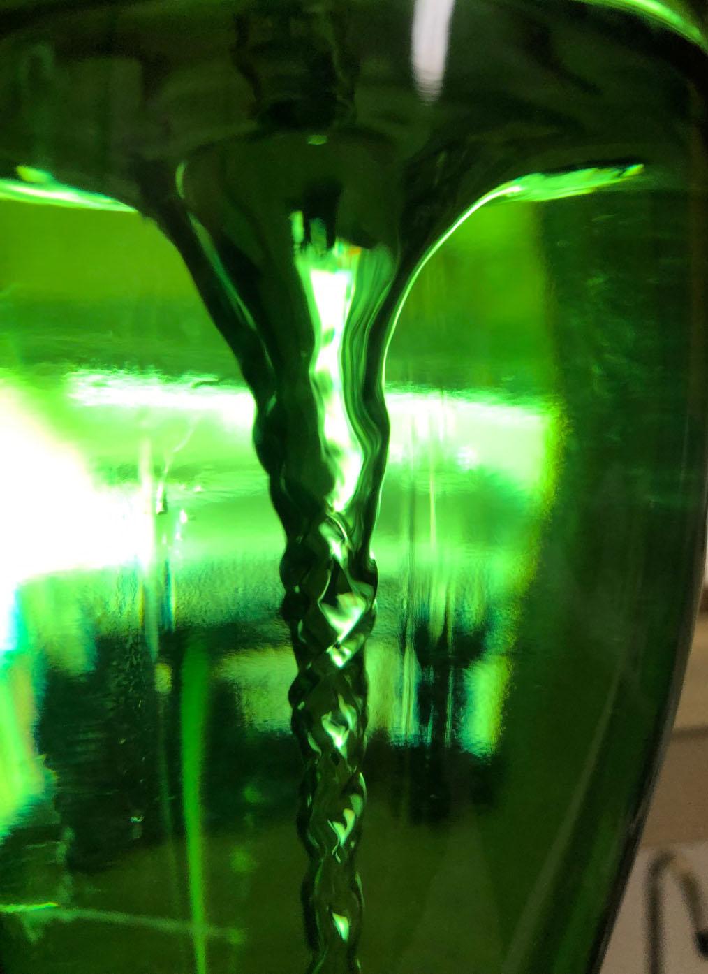
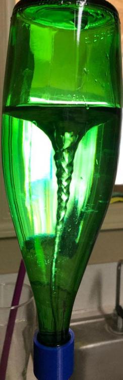
I am glad everyone likes the burner. I am excited at the idea of offering a product. I will work hard to make that happen. There is still a bit to do. Next steps in my mind: Finish vacuum table Test different investment recipes Modify model to fit commonly available pipe/tube for the choke Modify model to add set screw flats for the mix tube and accelerator (they are friction fit currently) Modify model to deal with aluminum shrinkage Cast this guy in aluminum True mix tube and accelerator ports in the lathe if needed Drill/tap for set screws Test him in several forges (top and bottom mounted) After all that is accomplished, I will have a realistic idea on whether or not I can provide them. After I have made a handful, I will have a better idea of what my cost and labor will be to make these things. After all that, it will be time to play with NARBs. I will have to research the patent stuff. I know nothing on the subject. I printed version 41 today to strengthen the ribs. It's performance is the same as v40. I am very happy with these versions. The next version will be a 3/8 mix tube version with the same design and ratios to see if it can support the 023 jet. Mostly unrelated, researching for these burners had me studying vortices a while back. This led me to building a tornado tube out of coke bottles for my daughter. That wasn't good enough. I searched for the right shaped bottles. I ended up with Perrier water bottles. I designed and printed a connecter which also has the right throat size to produce a powerful vortex in the bottle. Version 4 was successful. I can't stop playing with it. It forms 2 sets of helical lines: It takes a long time to run all the water out:

-
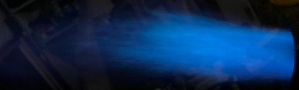
V40 is a success. It is happy to run on the peg up through 15 psi without a nozzle adjustment. At higher pressures, the flame enters purple territory with the 030 jet. The rib length was increased to 5/8" which happens to be 0.625", which I find interesting as the throat diameter is 0.622". Several of the measurements which I found best, happened to land very near multiples of the throat diameter. Below 1 psi with the 030 jet, 6 inch mix tube and the 1.25 nozzle: I had played with that idea. It would be nice to make back some of the money I have invested in my play to fund even more experiments. I worry about the liabilities of selling high output burners. That is my intention and the next stage in my experiments. My original intention was always to cast these in aluminum. Until then, they are just my toys. We have built a heat treat kiln for burnout and are in the process of building the vacuum table for investment casting. I had wondered if I were to offer just the inducer head in aluminum, if I would still have to worry about liability.
-
I have not made the STL files available yet. I am waiting until I am satisfied with the design. I would also like to get the cast process down, get some in metal, and crash test them in a few forges. I need to test them with the back pressure and I want to make sure they don't Chernobyl. Unfortunately, for the home brew, this burner head would require 3d printing and aluminum casting. Agreed. If a burner can not induce the correct volume of air for the volume of fuel and mix them properly, it is wasting fuel. My original intention was to learn about burners so I could build some that lower my fuel costs. I have learned quite a bit and continue with each version. What I thought was happening and what I should be striving for has changed a few times through the process. It's been fun. I am glad my experiments are useful.
-
I have printed several versions with the ribs at different angles. V38 is now the golden boy at an angle of 80°. I printed 60°, 70°, 75°, 80°, and 90°. V38 is capable of 1-15 psi with the big nozzle and the 030 jet. If I slide the nozzle back a bit, it runs on the peg at a very low output. I am excited about this one. The next one(v40) will be v38 with 5/8" long ribs instead of 1/2". Here is the gauge on the minimum peg with the 030 and much less nozzle overhang: Here is 1 psi with normal overhang: Here is 5 psi: Here is 15 psi: I should do something. The burner tub is getting deep.


-
I'm glad someone else likes these burners too. My wife can only look at so many plastic burners, which look the same, before even the pretend enthusiasm runs low. I think they are getting close now. Most of my recent experiments decreased performance. I still have a few more things to try, then the next step will be a bit more effort towards the casting side.
-
The angle I am talking about is the chord line in relation to the axis. Does that make sense?
-
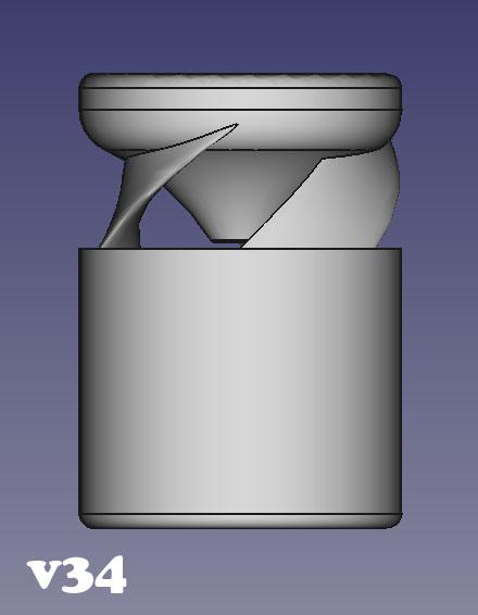
At this point I am changing the angle of ribs in relation to the jet to see what does best. My initial suspicions are that close to 90° starts to defeat the point in airfoil at all, close to 0° is a paddle which gets in the way vorticial flow. Version 34 happened to be at 75°.
-
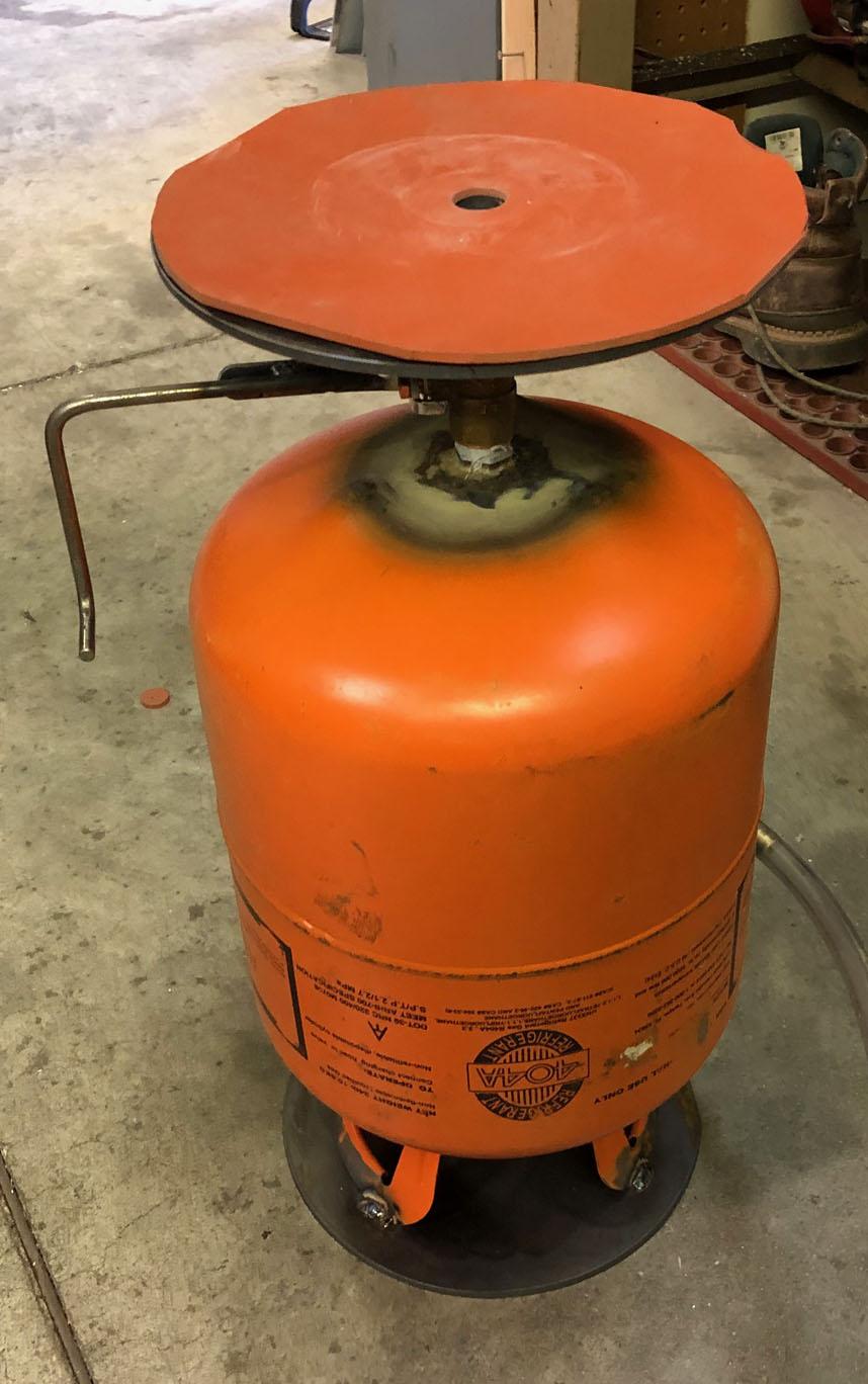
The 3/4 inch modified sidearm burner in my refrigerant jug forge has an 035 tip running at 5 psi and it runs for a long time on a 5 gallon tank. It runs quite rich and is too big so I have nice blue dragons breath. V34 uses an 030 tip and the same size nozzle with a smaller slower neutral flame. I am hoping for fuel savings. As to the profile, a picture would be great. Hand drawn is fine as well. I had a few curved airfoils to match the radius but they all had turbulence in the lower curve. I don't know much about airfoils so I most likely did them wrong. Also, because the air induces in straight lines from all directions until it enters the inducer, not all of the air goes across the airfoil in the direction it would if it were a wing. Having the vortex inside helps the streams flow across the foils like I originally thought. I think your idea is good one. Having the upper surface at a higher velocity and a lower pressure seems like it would be more likely to track the air across the upper of the airfoil to the outside of the vortex and the lower side of the next rib.
-
Naturally Aspirated Ribbon Burner. Photo heavy.
Another FrankenBurner replied to Frosty's topic in Ribbon Burners
I like the plenum design. Port size/quantity seems to be a bit of a balancing act. You need enough ports to let the inducer breath but they need to be small enough so the FAM velocity is above the propagation rate. You stated that it was blowing the flame off at the smaller holes, was that before the flares? I think you want the streams moving fast enough to be close to blowing off at start up. This is where the step flares may help hold the flame or starting at a lower pressure and increasing once the block heats a little. As the block heats and begins preheating the FAM, the propagation rate increases, so you want the FAM streams moving fast enough to prevent roll back. Before you scrap the block, block one/some of the ports and see what happens. -
Similar to v30 but the top of the reducer has no radius and the ribs are now rotated a bit more. This extra rotation has added to the flame stability and air induction. Previous versions which could support the 030 mig tip were at the low border of neutral flame. This guy accomplishes a good neutral flame at 2 - 15 psi with the 1.25 inch nozzle.