Another FrankenBurner
-
Posts
620 -
Joined
-
Last visited
Content Type
Profiles
Forums
Articles
Gallery
Downloads
Events
Everything posted by Another FrankenBurner
-
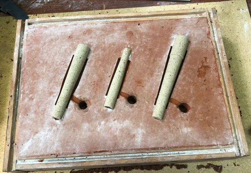
 I've been bad at reporting lately but we are still doing stuff over here. I've been playing with nozzle shapes and thanks to jwmelvin and Dan, I've been tinkering with inlet reduction shape again. 3D printed split patterns and core molds were used to create this mold.
-
Looks good Dan. I am glad someone else is playing around, thank you for posting your results. I am hoping jwmelvin continues to tinker.
-
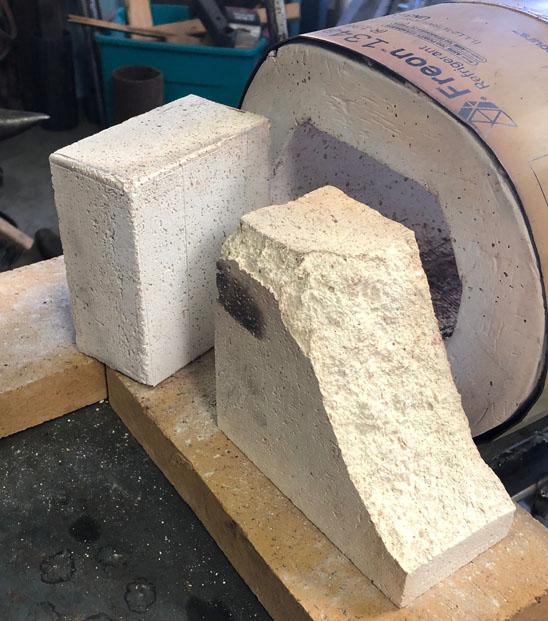
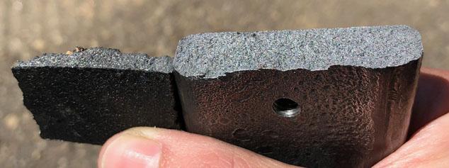
Yes, we were using Morgan Thermal Ceramic K26 bricks. That is what the busted up brick in the picture is. We have now had several of them fail.
-
Tired of cracking expensive bricks, we tried something. Rigidized blanket, fully coated in kast o lite. It has several hours of fire time. We are happy so far and making more. We also just faced the first one with matrikote.
-
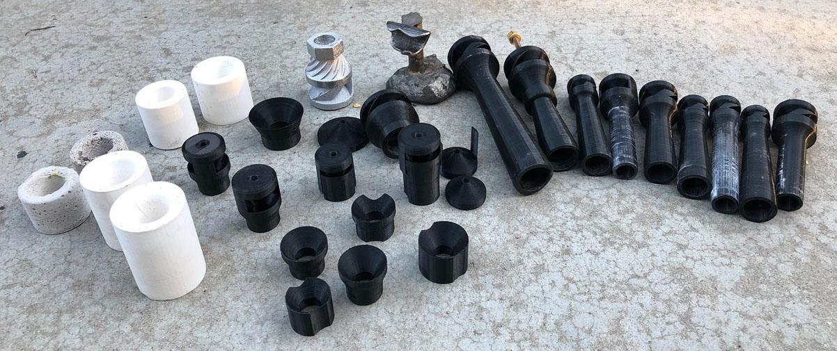
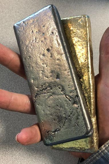
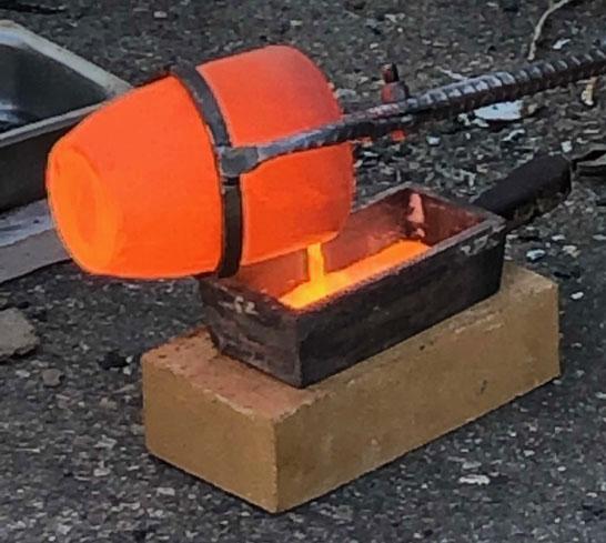
We did some pours today. Several failures and lots of learning. We are excited for the next attempt. We had one burner turn out. It is our best so far. We broke our iron ingot for some more learning. We also drilled a hole in it, tapped the hole, threaded in a bolt, and hammered the bolt. It is tough stuff. The cast on the left is a piece of the material used to pour the ingot on the right. When you are used to aluminum ingots, iron is heavy.
-
My bad on the numbering, I hadn't thought about it. I was just going left to right on the different sections. Since we are on the semantic subject anyway, I do like something Mikey had said which, in my mind, clears up some nomenclature. The primary flame is the flame whose air is coming from the burner itself, the secondary flame is the flame which gets it's air elsewhere. This, in my mind, eliminates tertiary flame. In the cases where it is currently being used, it is because the primary flame has more than one zone. Words are fun. I agree with Frosty on not being too nitpicky with all of this if you are just wanting a burner for your forge. While experimenting, I tend to pay a lot of attention to all of this to determine what is happening with the changes in each iteration. The truth of the matter, I have used a burner spitting out green flames and it still made metal hot enough to hit. If you adjust until you just pass the point of not seeing green, your burner is running great.
-
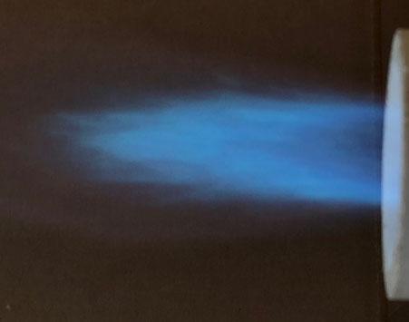
Tinker away. That's good stuff. Great way to learn. As to the shorter flame, you probably won't see much difference between 8" and 6.5" mix tube lengths in that regard. You may see your flame go darker blue. I have no doubts about your forge getting hot enough if it is insulated well.
-
Orifice diameter has a sweet spot just like mix tube length and nozzle overhang. It's all about balance. Based on your pictures and description, I think you have found a nice balance. I suspect a smaller jet will result in a very lean flame. Maybe a flame that will not stay lit. The only reason I see for going to a smaller jet is if you can not induce enough air. Edit: you just posted as I posted.
-
As to your flame, it looks good. The nomenclature for different flame envelopes depends on who you talk to. Number 2 in your picture is your primary flame. Number 3 is sometimes called secondary or tertiary. Number 1 is the void, it is fuel/air mix(FAM) which is not burning yet. I was referring to number 3 when I said secondary. As you see in your flame, the secondary is ghostly. This is good. Here is a labeled example of a rich flame to see the difference:
-
Shorter is less restriction for air induction but also less length for mixing. At the extremes shorter produces a bushier more squat flame, longer produces a lengthier sharper pencil like flame. For the forge, usually shorter is better as the flame is shorter. The forge also adds some back pressure which can decrease air induction. Too short and you don't get adequate mixing of the fuel and air. It's a balance. It is a lot to take in at first. No hurries, no worries. It sounds like you are where you want to be.
-
So long as I have proper mixing, I like shorter. Don't be too worried about it. Your flame looks good. If you see any green in the flame, play with nozzle overhang. I like the overhang to be just enough to hold the flame at the maximum pressure I will use. If you still have green in your flame after tinkering with the nozzle, start to cut small lengths off the mix tube. Pay attention to the color of the flame and pay attention to the secondary flame. If the color goes greener or the secondary flame looks to be increasing in size with the cuts, stop cutting. Or do none of this and be happy with the flame you have. It is a nice flame. Nice job.
-
You didn't miss anything. 3/4 pipe is 0.824" ID ish which puts you at 6.5" to 7.5" mix tube.
-
Thank you for the link Dan. It was a good read. We will have to use the kiln and do some wedge testing.
-
Thank you for the information guys. Sounds like another area for research and tinkering.
-
Thank you for the information. Casting is another fun way to work with metal. Plus we still get to play with fire.
-
Both ingots were tests. The iron ingot landed at 1.5 lbs. We went into it with some doubts and fears so we cautiously started nice and small. No more doubts or fears. We were happy the little burner did the job and we are excited. We have more experiements to do. We have some plans. I am playing with more then one new idea. It is exciting.
-
Dan:The top ingot grey cast and using a graphite clay crucible. You've mentioned bronze here and there, is this your preferred casting alloy? If so, any particular reason for that? Thanks Mike. I am very pleased with the new experiments.
-
Did some test pours today. We have a furnace heated with a v46 half inch burner which was used to cast some iron today. Also tinkered with a couple of new experiments. I am happy with their performance. Here is one of the flames:
-
Naturally Aspirated Ribbon Burner. Photo heavy.
Another FrankenBurner replied to Frosty's topic in Ribbon Burners
We have tried a few more of the K26 bricks as baffle walls and they have all crumbled in short time. We are now experimenting with other solutions. One thing you might try if you are determined to use the bricks, coat the flame face with plistix. -
Somewhere Tim Allen is grunting. How much burner are you after? What are you forging over there, anvils? Looks good. I am looking forward to the report back.
-
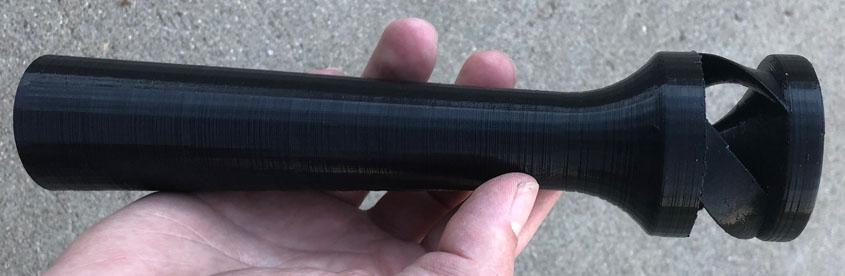
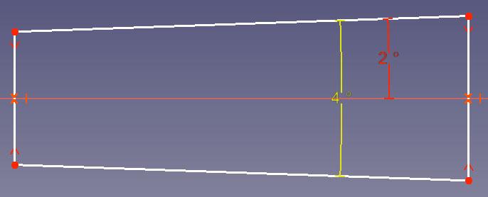
Those are looking great Dan. The outlet taper is fun to tinker with. It dramatically changes induction. I am printing another experiment today. I know exactly what you mean about the outlet diameter limiting the inlet diameter, I am fighting with that as well. The inlet diameter is the major dimension controlling throughput. Just to state the obvious, as you increase mig tip size, if pressure and flame quality are constant, your fuel usage and output energy increase. The difference in fuel usage between the 035 and the 044 will be quite noticeable. In pipe burners, this would be comparable to stepping up a couple of sizes. To clear something up, when you say 2°, are you meaning the angle to center line(red)? (Not the included angle, yellow) Thank you for the kind words. I have tested with/without the fancy intake with the outlet taper and it is still doing great things. About a single mig tip size difference. I think it is all about causing a vortex. There is probably a simpler way to accomplish this but I haven't thought of it. I think streamline is key here, anything aggressive hinders flow. Simpler would be better even if it didn't look as good. I am more than willing to abandon everything I have done to follow a better path if we find one.
-
Those NARB flames are looking really great. Can't wait to see what happens when you point them at a forge.
-
We are talking about all the possible ways that we might be able to produce something with what we have. The other part of the fun, how can it be accomplished? More reason to tinker.
-
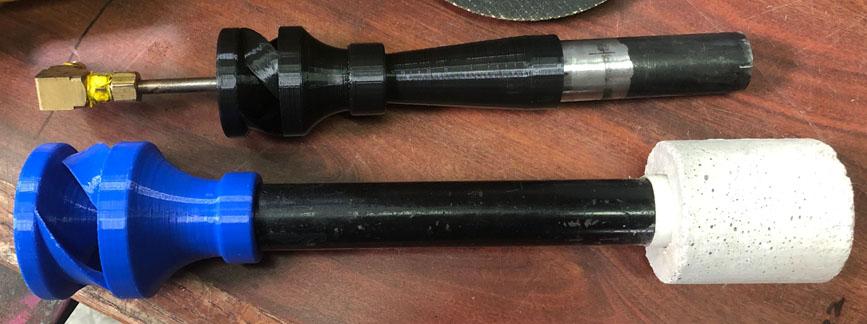
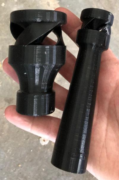
The 2° in the paper JWMelvin pointed out is the angle to center line which is only half of the 4° included angle of the taper. The 1:12 taper is an included angle of 4.76364°. The standard venturi outlet has an included angle of 5°. I usually use the 1:12 taper just because I've been reading about it for so long but I think anywhere in the 4-5° range will not cause turbulence through the expansion. I've been playing around with it as well. First I did the outlet on v46 which is posted above. Then I printed a partial length tapered adapter for v46 to upsize to 3/4 pipe. He induces more air then his 3/4 pipe burner counterpart. Then I printed a full length(8x) taper from 1/2" pipe down to a smaller throat. He attaches to 1/2" pipe as well. He runs the 030 tip with a neutral flame. His v46 counterpart is a better flame but when I open the throat a little bit, it will be superior. It still has the odd business of pipe after the fact. If only I could cast him in iron. The pipe after him makes him longer than v46 but it would be needed as a thermal buffer. I used a 4 inch section of pipe to add nozzles. Thank you again for the paper, JWMelvin. It has confirmed my findings and showed me that I am reinventing the wheel for the most part. I like that. The people before us were smart folks and we are spending all this effort trying to figure out what was figured out a hundred plus years ago. Not unlike the entire blacksmithing hobby. I had just started measuring burner pressures as a method of measuring burner efficiency. In the paper, the level of static pressure was also their measurement of burner efficiency. Once again, figuring out the already figured out. Good stuff. We are still working on producing the v46 inducers for supply as they are practical for home builders and make a hot forge but I will continue to tinker with the wasp waist. They will be superior for the NARB folks as they deliver at the higher static pressures.
-
JW: I was writing my response and Frosty posted. I will still post my response even though it says similar. No problem on the work, I enjoy it so it doesn't seem like work. Thank you for sharing your work as well, same for Dan and anyone else sharing their knowledge. You never know where inspiration will come from. My playing with the standard venturi again was a direct result of Dan playing with something similar in his experiments. You are correct about the venturi losing some energy but a better way to think about it is the venturi is using that energy. The potential energy of the fuel pressure in the cylinder is converted to kinetic energy at the orifice. This kinetic energy is the motor. The only purpose of the motor is to draw in air, mix it with the fuel and deliver it. I think the purpose of the converging inlet is both of the reasons you listed. The reduced pressure draws in the primary air. The increased velocity allows a violent clashing of fuel and air which mixes them and matches their velocities. You can aim the motor at a straight tube as Mikey has done with his burners. This requires higher input energy to entrain air. As such, his burners run a smaller orifice at a higher pressure to run neutral flames. In terms of fuel output(possible heat output), a smaller orifice at a higher pressure can match a larger orifice at a lower pressure. What matters is how well the fuel is burned and how much energy per time (eg btu/hr) is being sent through a given area. Any resistance or turbulence impedes this throughput. Energy in = Energy out. The less of it lost/wasted, the better the performance. You can point that kinetic motor at a converging/reducer inlet at the beginning of a straight tube like Ron Reil, Larry Zoeller, Rex Price, and I have done. This has the benefits previously discussed. They can run larger orifices at lower pressures which can allow more energy/time. You can add the diverging mix tube which is less resistant then a straight tube. Even less of the motive fluid's kinetic energy will be required. More air will be induced and the FAM will be delivered at a lower velocity/higher pressure. This can allow even higher energy/time. I think the outlet pressure also helps push the stream through upstream resistances. The only reason it is not employed more often is because there is nothing readily available which has the proper dimensions and can withstand the heat requirements. My inducers crank the velocity down the mix tube as I have increased the throughput. This high velocity blows the flame off the burner. I then employ a larger than normal nozzle to put on the brakes. This is some of that loss/waste of energy I talked about. Throughput could be increased even still if I could limit/eliminate this step by slowing it down gently. Here is my latest experiment v55: V46 1/2" inducer with the expanding mix tube. Eight hours of printing, a few minutes of running before melt down, big smile on my face. I knew what was going to happen and it still excited me when it happened. He delivers a highly oxidizing flame with the 035 jet which is better performance than my 3/4" pipe burner. He can not be categorized with the pipe burner sizing. A throat of 1/2 inch pipe and an outlet of 1 inch pipe. I had not seen that study on burners, thank you for sharing it. I will give it a thorough read. Hopefully that was all legible and I didn't say anything stupid. We have the potential energy of the cylinder, the kinetic energy of the stream, and the heat energy of the fuel. It's hard to keep it all straight in conversation when talking about more than one. Frosty: You don't have to measure water column against a vacuum but you can and I was. I regularly measure the positive water column pressure of natural gas against ambient pressure. When I measured the throat of the venturi against ambient, I was measuring vacuum. Water can be used because it is a very light vacuum. For bigger pressure difference mercury is used because of it's higher density. My vacuum pump is said to pull to 29.5 inches of mercury which is ~401 inches of water. Mercury also has a lower vapour pressure so it won't boil off under the deeper vacuum like water will. Thankfully I have Bourdon tube and analog/digital electric gauges for work. I will play with inducing air from the sides of a curved inlet. Sounds like a fun adventure.