Another FrankenBurner
-
Posts
619 -
Joined
-
Last visited
Content Type
Profiles
Forums
Articles
Gallery
Downloads
Events
Everything posted by Another FrankenBurner
-
I used k23 bricks as my baffle walls and within a few months, they turned into pieces. Not because of dropping or anything. The back brick was never moved and crumbled in place. I use the 2 inches of kaowool, 1/4 - 1/2 inch of kast o lite, and metrikote in my forges. More insulative, less mass, tougher then the bricks. You might armor the bricks with a refractory or kiln wash. Maybe that would prevent what I dealt with.
-
I would be concerned with the k23 bricks. All of them I have used, which were dealt forge thermal cycles have turned into rubble in short time. So far the k26 bricks are holding up much better.
-
MikeyI created a thread so as to not hijack this one with all my crazy ideas. Mikey: I would change my name but AnotherFrankenburner is pretty long to type. I do like the mad scientist stuff though. Patching together other concepts to see what works. Frosty: I like the idea of the aquarium, I feel I could learn a lot from that.
-
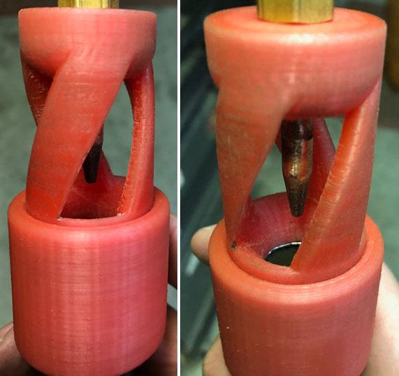
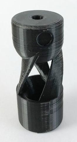
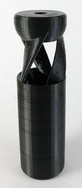
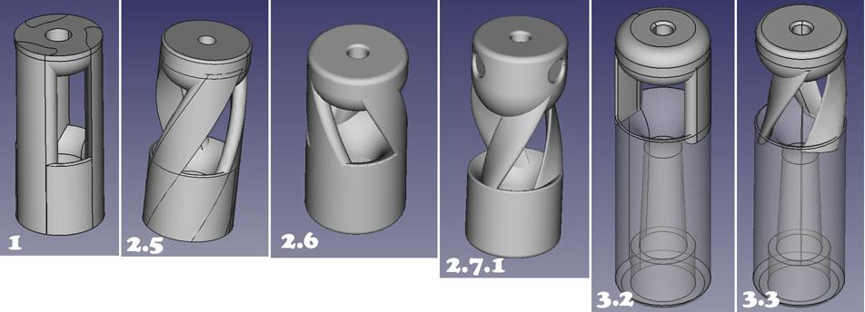
 I have been tinkering with burners for a number of years now, but the hard part was making the burners to test the ideas. In burners 101, John in Oly, WA had posted about some of his experiments in the vortex burner range. His experiments were created in part with a 3D printer. Seeing what he had done, I had a mind blown epiphany about 3D printers and prototyping. I knew almost nothing about them at the time. I learned about 3D printers and purchased one. I then had to learn about their idiosyncrasies, as well as 3D modeling and slicing the CAD models. As my CAD skills improved, my experiments got more complex. I usually print a burner head which fits a mix tube with nozzle. It is great. Have an idea, produce it reliably. Need to change it a just a little bit, reproduce it with those minor changes. Rapid prototyping. Click print and go to bed. I am playing with half inch mix tubes currently as they are big enough to be less picky but small enough that the prints are smaller. These are just so I can learn currently. I intend on casting some of the better models in aluminum. I also intend on eventually scaling to 3/8 and 3/4 burners once I am content with a few designs. I have a range of mix tubes precut from 7 inch to 2 inch at half inch increments, I have a few accelerator assemblies built and I have a few exit nozzles of different types. This allows me to quickly play with mix tube length, jet diameter, and nozzles without much fuss. Here are my experiments so far (in CAD form): I am whimsical with the version numbers. Some major failures in between. I have been labeling the burner heads in 3 sections. The accelerator block at the top, the ribs in between and the outlet below the ribs in the images. The nomenclature could use some help. The entrance to the "outlet" is an inlet. I haven't put much thought into it. The terms evolve as I gow. For a while the ribs were labeled vanes. Version 1: Learning CAD mostly. A small trumpet shape at the entrance of the outlet and crudely shaped ribs. I was working with the Mikey burner as the initial start concept. Not quite a tube burner as it decreases in size. I did not account for wall thickness on the 1/2 pipe in the trumpet so there was an abrupt corner unless the pipe was chamfered. Even with this, it produced a nice strong flame at higher pressures. It is the first flame I posted in burners 101. Version 2.5: A large improvement. The ribs are a bit smoother. I was going for a cutting edge and encouraging vortex (thanks to Mikey). A longer trumpet shape which exits in a smaller diameter to match the ID of 1/2 pipe. I posted some images of it's flames. Version 2.6: I reversed the direction of the ribs to encourage vortex the other way. Apparently I thought I was inducing a hurricane in the Northern hemisphere and so the coriolis effect needed tending to. I must have thought highly of myself at the time. I later wised up as the proof is in the pudding. Have to learn some how. I did radius the "cutting edge" but did not notice any major difference. I also decreased the length of the ribs so the air inlets surface area was in the neighborhood of 200% of the area of the throat. Version 2.7.1: I studied airfoil design and realized I had things all aerodynamically backwards. I reworked the rib shape and I also added a second axis of rotation to the ribs playing with vortex some more. It performs very well but I've barely had a chance to tinker with it. It got dubbed the twirly burner somewhere along the way. Version 3.2: This burner came before version 2.6 and 2.7.1 as I was playing with lower velocities (thanks to Frosty). It is a linear design using the wasp waste geometries. I initially posted an image but didn't have much time to play with it. At that time it was running higher velocities with a smaller mig tip. I eventually bored out a mig tip to 0.032 actual in an attempt at lower velocities as I was inducing too much air at higher velocities. I posted an image of that flame as well. Then a few posts later, I explained the burner in a bit more detail. It needs a bit of work but I wanted to dabble into lower velocities. Version 3.3: Why not? Take the ribs from 2.7.1 and plop them onto 3.2. Not so much to test an idea, this one it just for fun. I just CAD and printed today so I have no clues about him. I suspect higher velocities will be required as there is more drag from the ribs. They all use a sliding choke as it seems to do the best job of variable regulation and not just an on/off kind of thing. OK. OK. Real pictures. I only have a few. I was focused on the flames, not the burners mostly. Here is ver2.5 in a fashionable pink: (My daughter realized the printer can make toys) Here it is in the vise, setup for it's flame photoshoot: Here is 2.7.1 up close after some sanding: My final image is 3.3 warm off the printer still: I will add more images as I continue on. I can print in finer detail but for prototyping, it prints faster this way and it doesn't seem to influence it much. When I go to aluminum, they will be printed finer. As always with me, any discussion, suggestions, criticisms, or ideas are welcome and wanted.
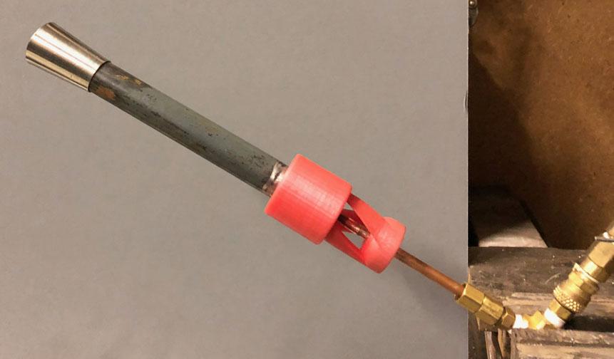
-
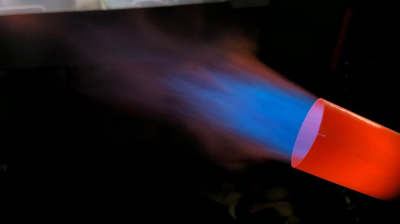
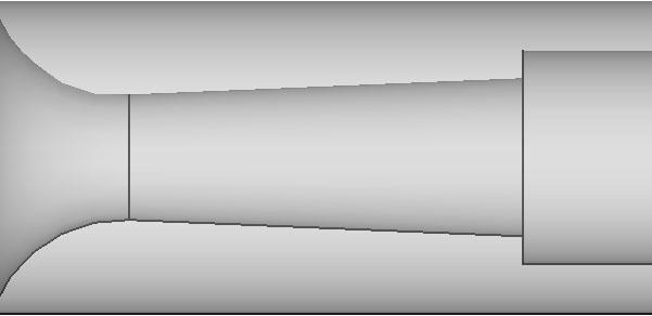
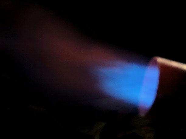
Thank you for the accolades again. They are encouraging. Though in this case, I shouldn't be getting credit for a 3/8 burner size. I used the same diameter as 3/8 pipe for the throat arbitrarily. This burner is sort of a cobbled monster so perhaps the mad scientist reference is applicable. I take it as a compliment. This burner is a partial wasp waist burner with a section of pipe after it and a nozzle. The inlet is a trumpet shape with about a 1.25 diameter down to the 0.493 throat. The outlet is an immediate 1:12 taper out of the throat for about 1.5 in to a diameter of 0.622 which is the ID of 1/2 pipe. Then a small section of 1/2 pipe to a 1:12 tapered nozzle. An 0.023 mig tip drilled out to 0.032. I misspoke with the 0.031. The ribs which run to the accelerator block are airfoil shaped to encourage spin which can be visibly watched in the secondary flame. If you look at the image I posted above, you can see evidence of it. Though I am not sure if the ribs add anything to the spin or if the reducer is doing the work. I will make one with straight ribs to see if spin still exists and to see what else changes. Half wasp waist burner, half straight tube. Not quite a 3/8 burner, not quite a 1/2 burner. With the mig tip size and pressure used, it puts it more in the realm of 1/2 burner btu output. An experiment into lower velocities inducing enough air. With the 0.023 mig tip unmodified, it induces enough air to run at lower pressures which was my goal. I wanted a "low" output burner for a coffee can forge. At higher velocities, it induces way too much air. I drilled out the jet to see what the high end output could get to which was the image I posted. Here is an image of the low output. It was when it first started so the nozzle was still cold. Sorry it is blurry. The flame is fairly laminar because the 1/2 inch pipe section is long. It is also sucked back into the nozzle as the velocity is low. My next low velocity experiment will be to get the largest mig tip running the lowest pressure I can into the smallest throat possible. Just to learn the relationships of the shapes. After that my next direction for experiments will go in the high velocity motive fluid direction and experimenting with mix tube length vs outlet nozzles size/shape. My thinking is that higher velocities have more energy to do more work and I will experiment with slowing the whole train down at the business end. Eventually leading to into NARB territory once I have a few different inducer designs to play with. I will take what I learn from all of that and move into 3/8 burners. I enjoy the spectrum of high velocity vs low velocity. Both have merit and high/low points. I am finding that balance is the key to every burner and all of their geometries. At low velocities, the difficulties are inducing enough air, mixing it properly and preventing flame suck back. At high velocities, the difficulties are regulating too much air, preventing flame lifting, and blowing all the btu's right out the door. I have also found that a balance can be found in most burners so they are stable but some have much better range then others. I am up for any discussion, questions, criticisms, ideas. I am just having fun over here.
-
I have been playing with inducing vortex down the mix tube. I have also been experimenting with inlet shapes to accommodate lower velocities. Here is my latest toy. The throat of this burner is 3/8 pipe ID (0.493 in) and the jet is .031 actual.

-
The hole in that shell should match the inner diameter of your burner mount. The flare and all should fit from the outside. A longer/taller burner mount would allow the flame end of the flare to be just inside the shell of the forge (almost outside the kaowool/refractory). With a longer mount, you could add a second set of mount screws which is nice as you can aim the burner to some extent. If you go through that trouble, you might take a look at forges 101 on the burner angle.
-
What is the volume of that forge? Seems pretty big. How much insulation is on the walls? What are the size of those burners? Is that first image a different forge then the last two? Either way, that first image shows burners which are too far into the forge. The burners should not stick into the forge at all, otherwise you risk over heating the ends of the them. If you do not have a regulator at the tank, this is the first thing to change, before changing anything with the burners. Propane tank pressures into the burners could easily be a big problem with how these burners run. If there are still problems with the burners after getting a regulator, then go back to my reply to these flames in burners 101 on page 53: Mikey has explained how to help burners like this. Don't change anything with burners until you have done the regulator.
-
Are you wanting to use natural gas instead of propane? If so, it is doable. You would have to know your natural gas pressure which is usually very low. My house is 7" WC which is 0.25 PSI. This is completely different then high pressure propane. I would advise looking into natural gas burners. They are usually the gun/blown type as the lower pressure means lower velocity which makes it harder to induce enough air. As Mikey stated, it's not more/less difficult, just different. It ties you to power unless you are running something off of batteries but hard fuel lines are usually in the same area as power. It is not portable if that is important. Some have said that it is more dangerous because if the power goes out, the fan will turn off but the fuel will continue. You could install a solenoid valve in the gas line which would eliminate this possibility. The upside, no running out of fuel half way into a project. If you go to a ribbon burner, more even heat, though it is not a requirement. Some places do offer high pressure natural gas. Usually industrially. Worth a check. That would change things. There are naturally aspirated low pressure natural gas burners out there commercially. They are much more critical in their design and are usually large in size. I don't recall any that I have seen homebrew over the years. There might be some out there. If the idea of natural gas is only to fix the improperly running forge and you are not opposed to propane, you can most likely get your current setup to run better. We would need more details on your current setup to advise. Some pictures of the flames, the burners and the forge would help greatly.
-
I would advise against the natural gas as a remedy for a poorly functioning propane forge. Fix the forge instead or first. Natural gas is typically plumbed in low pressures which will not be plug and play with your current poorly functioning forge. Natural gas also contains half the energy per volume of propane. While low pressure natural gas is doable, it is almost an apples and oranges kind of thing when it comes to burners. Entirely different requirements of the burner system meaning different designs. I recommend going to the Forges 101 thread and posting your exact situation with the poorly functioning propane forge so that people can give you their advise. Currently we know nothing about what is wrong with your propane forge.
-
I would make a joke about being naughty so that I could get extra coal but this is the gas forge section so I have to be good so I can get propane instead.
-
I called them a couple days ago. $4.98 a brick but shipping rates made it more expensive then my local $8.75 a brick. They also said they were not K26 but some other brand of 2600 brick which they thought was the same. Question for Frosty, do you have a corn cob pipe?
-
Wayne Coe sells both the metrikote and the plistix. He also sells kast o lite which is a castable refractory that a lot of people use(instead of satanite). As to metrikote vs plistix, people seem to be happy with either. As to burner angle causing flame spin, the flame tends to spin regardless. The first thought with burner position should be where is that flame going to impinge. The flame can damage the area it hits, this includes the walls of your forge and your stock. The high alumina shelf is tough stuff and is a good place to aim the flame. If you design it so the shelf is replaceable, all the better. All of this is covered in more detail in Forges 101. It is a great resource.
-
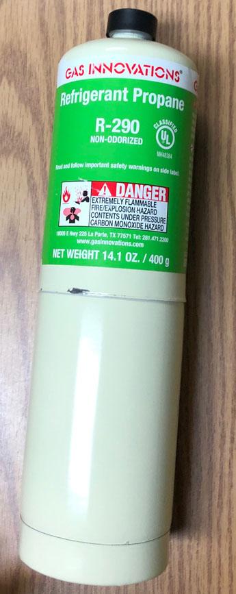
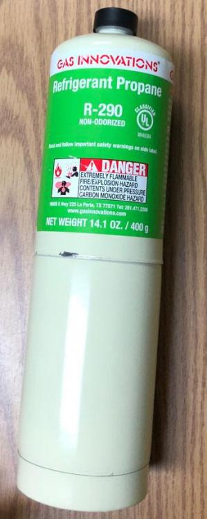
No problem on the info, it was all free to me. I didn't suspect you were aiming to use it as a fuel but I figured I better say it, just in case. R-290 is starting to be used again because it is not a fluorocarbon so it does not deplete the ozone. Good for the fridge and the forge and the planet, I guess.
-
You can go to the thread Forges 101. It contains lots of information on building a forge. As to the brick in the bottom of the forge, it is a large heat sink which will take a lot of fuel to heat and usually ends up in colder forge temperatures. The general recommendation is to wrap the ceramic blanket all the way around and a thin piece of high alumina kiln shelf on top of it for a tough floor. The wise ones are steering people away from the ITC-100 as it is not good for forge use. They are recommending plistix or metrikote. Good news, they are both cheaper than the ITC. The burners entering at a 45, why? The general recommendation from Mikey is at 2 on the clock, pointed downward enough to strike the near side of the floor but still with enough angle to promote spin in the forge. The downside to this arrangement, when the forge is cycled off, the burner becomes a chimney. If you go this route, close the chokes on your burners after shutdown.
-
Some think LPG stands for liquid propane gas but it stands for liquified petroleum gas. It is a mix as you stated. Usually containing propane and butane as the main components and some others like propylene make up a small percent. There is also an odorant added so leaks can be detected by smell. The mix has to meet some guidelines but it can be different from batch to batch. Depending on time of year, the propane/butane ratios change. All of this is what the propane guys told me. R-290 is refrigerant grade pure propane(99.5%). A mix would have a different pressure/temperature relationship which would change the requirements of the system using the refrigerant, so it is important that it is always the same. I wouldn't pursue it as a fuel though. There might even be laws against as it is not odorized, but I'm not certain.
-
By trade, I sometimes diagnose propane systems and appliances. On one of my jobs, I ended up finding a low supply volume at the appliances. The supply line dropped from the tank under the floor about 12 inches, ran underneath the place for about 30 feet, and then rose out from under the floor to the appliances. This plumbing arrangement formed a bit of a trap and I ended up finding that entire 30 foot length of 3/4 run filled with a yellow oily smelly liquid. I suspected it was from the odorant they add to the propane. Moral of the story, listen to Mikey. If a 3/4 pipe can be blocked, imagine how small the orifice is in your burner. Another thing about propane but in a different direction, propane is a refrigerant(R-290). This is why when talking of mixing propane with air, things are brought up like vapor vs gas, mist, and droplets. There is much more going on then spraying one simple gas into another. Without getting too much into it, your cylinder is filled with partial liquid and partial vapor/gas at a specific balancing pressure based on it's temperature. This balance is because the head(vapor/gas) is as saturated as it can be. The tank supplies from the top so it is supplying this head. Saturated gas. Think of it like steam coming out of your tea kettle, heavily saturated gas. As this mix gains temperature, it becomes less saturated. Long supply lines can aid in this temperature rise. In the land of refrigeration, the vapor is usually superheated in the evaporator to assure liquid does not make it to the compressor to cause damage. While there are systems out there which purposefully superheat propane for combustion use, I advise strongly against it in home brew anything. Safety first. Funny enough, have a look at one of the ways R-290 is supplied. Same threads even. A bit expensive for running the portable barbeque though.
-
No problem. As far as I know it currently, as you cut off mix tube, you reduce the length of drag which allows the burner to induce more air, however, you are also reducing the amount of length it has to mix the fuel/air so it is a balance. If you do go ahead with cutting off mix tube, you might look into different nozzle designs (in your case the threaded area you tapered at the end of the 3/4 pipe) since you will be cutting off your nozzle anyway. Having a separate piece for a nozzle allows more adjustability as well as not having to make a new nozzle each time you shorten the length of the mix tube. Once again though, I would do nothing until the experts give their opinion. They may come in and say I have it all wrong.
-
Inside the forge? For what reason?
-
That is a decent looking flame. It weel heat. Nice job. It is a reducing flame which means it is not inducing enough air like I suspected. It will heat as is but it will not get as hot and it is pumping out the carbon monoxide so be sure to be well ventilated as we all should. Some people prefer to use a reducing flame as it can prevent scale building up in the forge. If you want to make it better, the first thing I would try would be shortening the mix tube(3/4 tube). You stated it as being 9 inches but you also say with the end bell shape which I am not sure I follow. The general rule of thumb for a starting point length is 8 to 9 times the ID of the mix tube. If you have a mix tube diameter of 0.824 in(3/4 pipe) then this would be 6.9 to 7.4. If you go this route, start longer then that and cut off a little at a time. Can't add it back after you cut it off and all that business. Other things that could be done are increasing the size of the end reducer and looking into using a mig tip instead of a drilled hole for the jet/orifice. Both of these would be more difficult then cutting off lengths of the mix tube. All that said, I wouldn't do anything until the experts give their opinions as my knowledge is limited and I would not want to steer you wrong. Also, the flame looks good and can be used as is. One of my forges has a burner which has a more reducing flame and as long as I am willing to accept the increased fuel usage and carbon monoxide it makes the forge plenty hot. Also, to note, even though you plan on refractory in your forge, it is still recommended to rigidize your ceramic blanket. You can do that before the refractory and use your burner to heat cure it. On page 2 of Forges 101 is some information on the process.
-
I would be very happy if I could find a case for $60. I am currently going the pottery supplier route and paying almost $9 a brick. Amazon doesn't seem to have much, or I am missing them and ebay is where the shipping prices are sometimes $11 for a $6 brick. I'll keep looking, thank you.
-
Thank you for that. I used a k23 brick as a baffle wall for about a month before it turned into a pile of rubble. I am now using k26 bricks. I armored one with metrikote and another with kast o lite. I have not been using them long enough to say anything about them other then they are still currently intact with no cracks. I have had a hard time finding them affordably.
-
Sort of an older style Ron Reil burner. His website has a lot of information about similar burners. If you could provide an image of the flame it produces, that would help you get input. Also, a better set of dimensions. Are you using a mig tip in that cross pipe or just a drilled hole? You state orifice tube so I suspect the latter. What size orifice? How long is the 3/4 pipe? Just looking at the pictures and taking some guesses here. The 3/4 pipe looks to be on the long side and the reducer might be a bit small on the large ID. This burner may have a problem inducing enough air. An image of the flame can be looked at to see if this is true. Also, the knob is connected to a small valve which is most likely a brass on brass tapered assembly. There is usually graphite grease but no real seal on the knob shaft. On the bbq it was probably using 11" WC pressure which is about 0.4 PSI. I am not sure how that will do with what you are throwing at it. Either way, I have seen them at the 11" WC leak out the knob shaft. In a few cases it ignited and sent a good flame out. At higher pressures, I could see it not being fun. While it can be used to meter to some extent, it is more of a guillotine. Better control would come from a needle valve. All that said, it's a cool looking burner. The last burner I thought might not induce enough air turned out a beautiful flame. Did you bell the 1 1/2 pipe? How did you go about it? I look forward to seeing the flame. Then some of the wise ones can chime in and if there are troubles they can give advise on how to make it better. I also recommend burners 101 thread on this forum if you are into designing your own burner. It is a long read but it has a lot of information on the science of burners and their parts.
-
No problem on the clarification. I look forward to updates on this burner so that I can learn from them as you have.
-
As to the joy of tinkering, this is playing with fire but involves math, science and trial and error. I can't help but enjoy it. Years ago this process involved a stick, a campfire and constant scolding's from my parents.