
Another FrankenBurner
-
Posts
619 -
Joined
-
Last visited
Content Type
Profiles
Forums
Articles
Gallery
Downloads
Events
Everything posted by Another FrankenBurner
-

Video of curing and other questions
Another FrankenBurner replied to Thursigar's topic in Gas Forges
I would definitely remove/replace enough line to get the kinks gone. The corners of the kink are now very weak, especially if the kink was sharp. If you didn't kink them very badly, you may not have leaks, but I don't like to risk it. Copper is cheap compared to catastrophe. I am a refrigeration tech and have fixed several kinks and previous kinks which leaked(refrigerant). Leaking 30 psi propane near an ignition source sounds like no fun. I also recommend a 1/4 turn ball valve after the regulator before the hose. A remote safety shut off which is quicker then trying to turn off the bottle. You can also plumb your gauge down near/after the regulator to make it easier to see while adjusting. As to the gas(yellow) tape, it looks like you taped the flare fittings. Don't tape flare fittings. Flare fittings use a metal on metal seal. Taping the threads does nothing but get in the way of threading the fitting all the way which could prevent a seal. Tape the pipe(NPT) side of the flare fitting, just not the flare side. Also, for next time, you don't have to tape the mix tube where it attaches to the tee fitting. The gas tape in my tool bag states 3 full turns on less then 1 inch pipe and 4 turns above 1 inch. Some other brands of gas tape state a minimum of 2 full turns. It's a good looking and working forge. Nice job. -
You're welcome, from me as well, sir. Though, the advice I gave you, IIRC, I was first made aware of from Mikey's book. Maybe you just need to thank him twice. It's a good looking and running burner. Nice job.
-
Based on the large exit flame at the burner end of the forge and the small exit flame at the other end, I would guess that a lot of your heat is coming out of the burner and blowing right out the front door. It may have been hotter if the burner were closer to the center of the forge. I finally went and looked up the atlas burners you were talking about and see that your forge looks similar to theirs, in terms of burner placement. Perhaps aiming it more towards the rear would cause it to push more heat that direction. The atlas forge looks to be lined with drilled out soft fire brick. Depending on which firebrick they used, it's durability may be very poor. I am also not the biggest fan of their burner design. I don't own any of their stuff, so I have no clue about them. Based on your burner, I'm sure their forges get hot enough to work, they just need more fuel to get the job done. In smaller forges, this probably matters less to people. That said, your forge looks hot. Nice job again. Don't mind my rant. If you are happy with your forge, it's a good tool.
-
I recommend trying it with the choke closing from the opposite direction you have it now. In my experiments, a choke which closes like yours acts more like an on/off. Slide the choke toward the flame end and have it close toward the gas inlet end. In this configuration, it did much better at linear regulation for me. Hopefully it helps.
-
Sounds good. Let me know how many you want ahead of time so I keep them, as we normally scrap them. They will have been properly evacuated and purged when you get them.
-
Call around to the HVAC service and restaurant appliance repair companies in the area. You will probably find some refrigerant jugs for free with a few phone calls. They may insist on drilling a hole in the tank or cutting off the valve, this is for liability to prevent using the tank as a pressure vessel. If so, ask them to drill the hole in the top or bottom as you would be cutting that section off anyway. That is what I do for a living. If you happen to head to the Boise area, I can give you several. If you get one, the jug may still contain a small amount of trapped refrigerant. It should have been reclaimed/evacuated but be cautious of it still. If you burn refrigerant you can produce some bad/toxic gases. Open the valve and make sure it has no pressure. If it does, return it and advise the company. The cylinder will have a safety blow disc on the top. It is easy to center punch through or drill through as it is thinner then the rest of the cylinder. With the valve open, push some compressed air into the hole you made so it sprays out the valve for a few seconds. You are now safe to plasma, grind, weld on the cylinder without possibly producing poisonous gas. Don't be scared away by this, it is easy to be safe. The only other caution I have read is about the paint on the cylinder. I have read that during removal, the paint dust is an irritant. I don't know it to be true but I wear a respirator and do it outside when removing the paint. I found a wire cup brush makes this a fairly easy task. The cylinder is 9.5 inches in diameter. If you use 2 inches of ceramic wool and a half inch of kast o lite and metrikote, you end up with about 4.5 inches ID by 12 inches (190 cu in). I do most of my forging in this sized forge as it is small enough to not be too fuel hungry but big enough to accommodate a lot of different projects. If you worry of shell thickness, you can ask for the jug to be R-410a refrigerant for a thicker shell. I don't worry about it though, any refrigerant cylinder is plenty thick to support itself and burner mounts and makes for a lighter forge.
-
What issues would this cause if it were a material which cared? Differential expansion top/bottom/left/right vs the corners?
-
There is a heat cycle to finish kast o lite. Most people let it dry for a week or so and fire their burner for a minute and let it cool, then 2 minutes, then 5, then 10, and so on. I did something similar with mine and it turned out well. Just don't turn the burner on full blast and let it go as the water escaping quickly causes problems. If my forge has sat for longer then a few days, I also start up slowly as I once read that refractory materials absorb moisture. It sounds like this forge does not have the 1" of ceramic blanket that your can forge had. This adds to the mass and reduces the insulation which will require more fuel to heat and may lower your temperature limit. It looks like you have a higher output burner to heat it so it may not matter if you don't care about fuel usage. Your outer shell may also get quite hot. I look forward to your update to see how it performs.
-
It is a good looking set of tongs. A lot of people struggle with tongs in the beginning and this is a simple way to get something functional quickly. Do they hold your pieces securely? Could we get a picture of the loop on the end?
-
In the images, I see one with a set of lighter duty tongs. Did you make them? If so, did you make them using this forge? Did you use the same 1/2" round stock you show in Forges 101 or something else? The rivet looks to be smaller stock, what stock was that? Any shape in the bits to help secure the work? (half round or grooves) How do they work for you? Do they hold the work securely?
-
What he said. I want it to be as affordable as possible. Aside from carbon monoxide, wasted btu's are why a little green in the flame and/or the presence of blue dragons breath are things I try to eliminate, unless needing for a reducing environment or pushing the burners for welding. Why waste fuel if you don't have to? To my understanding, insulation thickness has a tipping point. After a certain thickness it stops being useful all together and at that thickness we had passed the point of practical quite a bit before. The extra cost of the insulation vs the length of time it would take to offset that cost by the extra cost of running the forge (ROI). The higher the temperature differential, the thicker practical becomes. As Frosty said, if the shell can be touched, I consider it good enough. Striving for more makes the forge bigger and probably doesn't save much in fuel. As Mikey stated, bigger differences in fuel use might be achieved with other upgrades which would be a better use of the funds. For me, the biggest change in fuel consumption was noticed when I spent the money to build an idle circuit. I like the idea of a cheaper secondary insulation if the forge size doesn't matter and squeezing the btu's does matter. It makes me want to put a thermocouple in the middle of the two inches of ceramic blanket to see how much heat is making it that far. Maybe one inch of ceramic blanket could be used and a secondary insulation after that. That is a good looking micro forge. Much hotter then all of the 2 brick forges I have seen. Nice job. That sounds like a refrigerant jug forge. About 4 inch diameter at 12 inches.
-
I will do both. Thank you for the recipe. I have found a few recipes which are all similar. Usually 1/3 plaster, 1/3 silica sand, and 1/3 something else. (clay, grog, hydrocal, etc.) One recommendation to paint the item in a good investment (he recommended Kerr products) for detail and then use the diy recipe for the remainder of the mold. I will experiment with all of the above. My casts do not need the intricate detail that jewelry requires.
-
We are relying on that for safety net, especially since the prototypes are run in plastic. For a few experiments we have used shorter steel mix tubes but most of them are 5 inches or so. As we obtain higher nozzle temperatures, the mix tube transfers that heat. Once the burner is aluminum and mounted in a forge, we will be making your secondary air choke to control secondary air and block radiant heat out. I am now playing with larger diameters which will have some hollow space at the mix tube end of the cast. I am going to experiment with cooling fins, like air cooled engine cylinders, on the outside of the cast.
-
Did you happen to be using a flask for this failure? What investment are you using? I've heard the sand/plaster mix for foundry/forge formation. It works equally bad for that from what I've read.
-
I was cooling them to room temperature. We just barely started on the casting phase and we had not done the homework. The investment used has been plaster of paris. I have done a bit of homework since your post to learn what you are talking about. I will be building a vacuum platform and using flasks on future molds. Thank you for all of the information and making me do my homework. I may eventually shift over to the wax filament but I have the Bowden system and read that direct is the only way to go for the wax. I'm sure I will come up with some questions. Controllable pitch ribs sounds like a fun experiment. I will have to create a different model to play with that. I was demonstrating the difference in exposure. I was able to take a picture of a purple oxidizing flame which would have been determined rich based on photo alone. I always judge the flame based on what I witness. What I witnessed was the nozzle temperature of the left image and the flame of the right image. Thank you for posting all of your flame reads throughout the forums, so that I could learn to interpret the flames. Without that, all of these experiments would not add up to much. I sure have considered it and intended on doing so. I am pretty sure, the more we strive for lower velocities, the more the burner is going to look like a wasp waist burner. As to the length, are you talking about the length of the trumpet shape or the length of the ribs? At first things moved fast with a few different big picture tests. Now I am getting into the nitty gritty. I am going to start changing one thing at a time with each print to determine what changes. I still need to play with the practicality of the helix on the ribs, the shape of the airfoil, the angle of the ribs, the diameter and curves of the trumpet shape, and the ratio of air inlet to rib surface area. That is a great thing. Keep them coming. Anything that you want to test, I am willing to test.
-
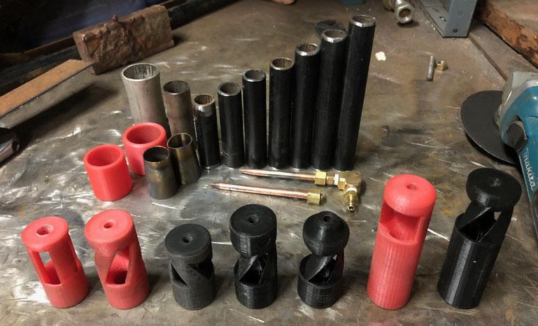
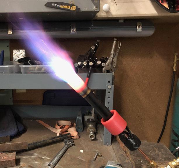
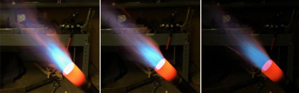
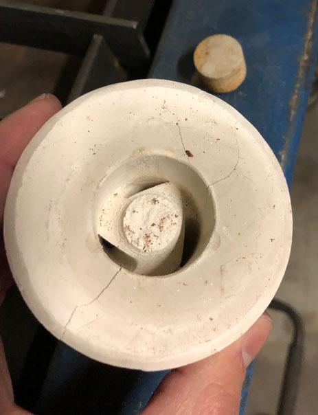
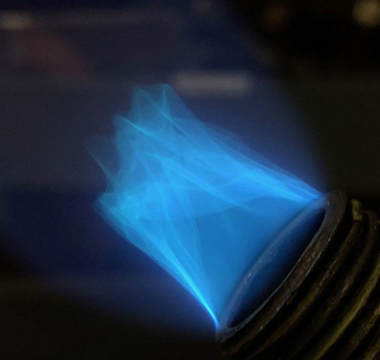
I made it out to the shop to get some proper images. I didn't have much time to tinker with the new versions so I still don't know much about them. As suspected, version 3.3 demands higher velocities then version 3.2 but hasn't been evaluated for mix tube length, accelerator diameter, or flame characteristics. Here is a lineup of the toys and some background clutter: Here is a shot to show 2.7.1 hosting fire. The flame looks terrible but that is due to exposure mostly. When getting images of flames, it is very difficult to get them to look like they actually do. To demonstrate, here are some examples. All images are the same burner, as above, at the same pressure, taken at the same time. The only change is the exposure settings. What was actually witnessed was the nozzle color from the left image and the flame from the right image. As you can see, the left image makes the flame look very rich and the secondary flame looks huge and some what lazy. The middle image looks still rich with a smaller less lazy secondary flame. The right image, the flame looks pretty good with a ghostly straight secondary flame but the nozzle looks relatively cold. I played with 3.2 some more and was experimenting with low end output. This is coming directly out of 1/2" pipe: My father has been working on the molds and we had a failure. The molds come out perfectly clean but it cracked during cool down so we will be adjusting the cooling program: If anyone who knows more then me (big crowd), ever sees anything I got all wrong, please educate me. I like to do things the smarter way and I don't have a problem with correcting my wrongs. For now, unless there is a lightbulb moment, I am going to tinker with what I have on the table until I am satisfied. Then I am going to try to select one of the versions or create another version from my learnings so I am working with a single version and making small modifications to it.
-
Thank you sir. The water is warmer at this end, that is interesting.
-
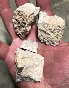
Here is some of the remains. These are Morgan Thermal Ceramic K23's. Used as a baffle wall outside of the forge for a few months before crumbling was noticed. The MTC K26's are doing much better so far.
-
Enewguy: These burners are all NA. Introducing things of that sort add resistance and possibly get in the way. Mostly, they are above my current intellectual pay grade. My current direction is to streamline everything which is why I am striving for lower velocities. Lower velocities make it harder to induce enough air, mix it properly, and output it at the right velocities. Once I have done some figuring out there, I will play with increasing the velocity and adding purposeful turbulence to do my bidding. I really suspect the end result of all this will be middle velocity induction device feeding an equally experimented NARB. The extra velocity to afford us the extra turbulence while also outputting higher btu's with a smaller induction device. If the proper amount of air is induced and mixed, the only velocity that matters is the flame exit velocity and nozzles let us play with that, as long as we account for them. It's all about balance. At least this is all as I understand things currently. Ask again tomorrow. Gibson: Thank you for the information. I will look into it. My father and I have built a number of CNC machines (router table, mill, plasma table) and figured we would give a printer a shot, seeing how simplistically the Ender 3 and CR-10S are built and still function very well. Frosty: I had the same golf ball dimple curiousity. As to the accident, that sucks. I too have dealt with a major health crisis recently which affected the processor. For a time, I was very concerned that I would lose that part of myself and it bothered me as much as the concerns of possibly dying soon. What you have been dealt, I feared very much. I have to work within the new rules of my damaged mind but it sounds like you have a much longer list of new rules. VainEnd84: I got it now. I thought fluting was about bringing the weight down. HojPoj: I doubt I will upload the files to Thingiverse. I worry of liability when talking of high output burners and uploading them onto a site which isn't about them for just anyone to find, irritates that worry. I am considering uploading them here eventually once I have more time to narrow down what I am doing. Frosty once brought up some images of an old bad design he wished would go away and I am trying avoid that. The mix tube is friction fit. I imagined a little better centering that way, even though the pipe could be eccentric a bit. Also, the NPT threads are a fun one to CAD so slip fit is easier to prototype.
-
3000 posts for Mikey, nice. Thank you for helping us all that much. (We won't look at frosty's post count) I changed my handle to AnotherFrankenBurner but it was so long, it wasn't all visible on the left side of the posts so I shortened it to FrankenBurner. I figured it out thanks to Irondragon Forge & Clay's handle. Just needed a space.
-
VainEnd84: I can add anything we all can come up with if it is described concisely. What do you mean by ridges? It might just take me a bit to learn whatever I need to in order to model it. I had toyed with the idea of dimples down the mix tube, like the surface of a golf ball. I like ideas. Enewguy: I have a model(2.8) similar to 2.7.1 but the ribs continue the entire length of the trumpet into the mix tube. I haven't printed it yet but I suspect that the ribs will actually act as a stop in the vortical flow within the trumpet shape. I will be playing with the devices in water to gain a better understanding of the dynamics (thanks frosty). At that point I might know whether is would be better to try to control the vortex like that or just encourage it and let it go organic.

-
Frosty, I had another thought. It would probably disrupt the FAM stream but if the entire mix tube were aluminum, fins of some kind could be printed inside the outlet end of the mix tube. This would act as a heat exchanger to both cool the mix tube and preheat the FAM. It would have to be balanced to prevent suck back and also melt down. High output burner melt down sounds like no fun. I have 2 shutdown ball valves(one at each end), the idle valve assembly, and the final needle valve. I like safety nets.
-
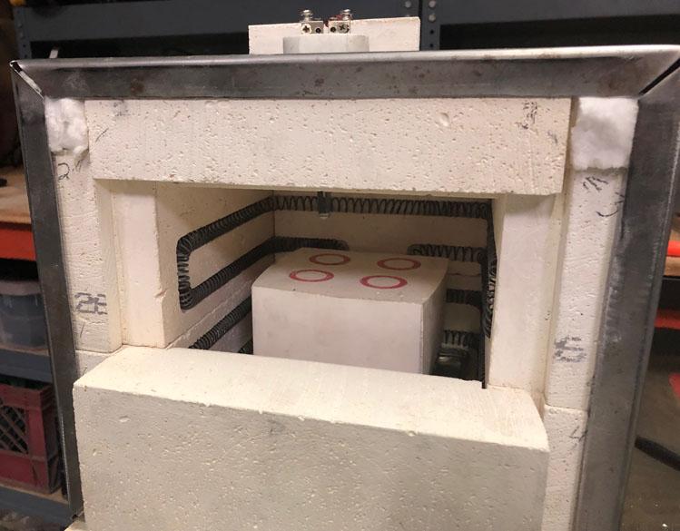
Buzzkill: I intend to post anything note worthy going forward. I held back in burners 101 so as not to hijack it with my feats and failures. Gibson: I am using a Creality Ender 3 printer and a 0.2mm layer height for the quick prints. I go to 0.1 and 0.05 for finer prints. HojPoj: PLA filament currently. Frosty: I had not thought of bronze cast but I have been printing in plastic and lost PLA casting them in aluminum. Symmetric models can be split and go to green sand. I had the same thought, the FAM stream cools the entire assembly during running and the choke is closed at shut down. If need be, heat radiating fins could be added to the mix tube if the FAM didn't provide adequate cooling. So far, in plastic, the only time heat was a concern is when I bring the nozzle into the orange ranges with a shorter section of mix tube. Even then, no plastic heads have melted down because of it. Only one Chernobyl incident which was due to a partially open needle valve and a partially open choke at shutdown. So far I have been using the steel mix tube as a safety net between the nozzle and the plastic because all testing has been open air. If the entire mix tube were aluminum, I'm not sure yet. Though, my thoughts were to design the forge to keep the flame off of the burner completely by casting the final nozzle into the forge with kast o lite or metrikote. Just have to balance the velocities. I had another thought you might like. 3D printed forms for NARB blocks. Custom count, dimension, and taper for the ports. I will get there when I am satisfied with the burner play. I suspect more smaller ports means a shorter block to maintain laminar which might be adequately cooled with lower input pressures. Also, the ports could be sized according to their position for even FAM distribution across the plenum. Mikey: Part of my 3D printer epiphany was the ease of manufacture. Once I have some of the bugs worked out, anyone with a 3D printer, or who has a friend who has one, or who can order from the online 3D printing services (some of which can deal in stainless steel "prints") can have one with exacting specifications. As to the spiraled air openings, I have not determined their practicality yet. I need to reproduce some of the burners with the exact same airfoil shape minus the spiral and see if difference is noticed. I'm not sure if they help or just get in the way. They sure look cool though. Gibson: I have come across lost casting. I have also discovered MachinableWax but I will have to change up printers as it is too soft for my extruder type. There are plans in the works for a home brew printer with dual extruder for printing in wax with one and a water soluble filament for support structures in the other. For now, lost PLA works and clean burnouts are easily obtainable with controlled heat cycles. In my case 2 hours at 100C, 2 hours at 200C, and 4 hours at > 500C. It is mostly a drying, then a melt out, then a burnout of any trapped portions. The molds come out completely white with no remnants or charring. Here is a shot of the home brew heat treat oven built for this purpose with some burner heads ready for burnout:
-
What are the dimensions on the front door there? What is the length of the forge? Say the door is 4 X 9 and the length is 12 inches, you are looking at 432 cu in plus some as the ceiling is vaulted. It looks like the door is probably a bit smaller then that though. What pressure are you using?
-
If you were to use the larger disposable helium tank or a 20lb propane tank, it would be comparable in forge size as your current brick forge.
