Steamboat
-
Posts
261 -
Joined
-
Last visited
Content Type
Profiles
Forums
Articles
Gallery
Downloads
Events
Everything posted by Steamboat
-
Thanks, Frosty. I hope you're feeling better soon! Al (Steamboat)
-
Thanks, Hibby. I made the brackets myself and welded them onto the base. The iron wheels were cannibalized from some casters I picked up at one of the big box stores a while back. The wheels are up off the floor about 1/4" and only contact the floor when I tip the vise backwards. Keep in mind that if you plan to roll your post vise over soft or rough ground, you will be better off with larger-diameter wheels to negotiate the terrain. A little extra tread width would not hurt either. I only use my equipment on asphalt or concrete, so it's not a concern for me. By the way, since you are working on a post-vise stand, you might want to look at one that I built to get a few ideas: https://www.iforgeiron.com/topic/49549-what-did-you-do-in-the-shop-today/?page=206&tab=comments#comment-616374 Al (Steamboat)
-
Frosty, thanks for the feedback. I think you may have misread something, or perhaps I left out some helpful explanatory information. Maybe this added information will clear things up: None of the lock nuts on the any of the pivot bolts are putting any strain on anything. The pivot for the hinged jaw is set up the same way as the other pivots. In other words, only one of the pivot cheeks for the hinged jaw is threaded, and the pivot bolt slides freely through the hole in the other cheek and freely through the jaw insert. I left a small gap under the head of the bolt, so that the bolt head is not even touching the pivot cheek for the jaw, so there is no pressure at all trying to squeeze the pivot cheeks together, which means that there is absolutely no bending load on the jaw's pivot cheeks. In fact, I could cut off the bolt heads on all three of the vise's pivot bolts and it would not make any difference. If you look at the three diagrams of the beam pivot in my original post, the same basic approach applies to the hinged jaw pivot and the foot pedal pivot. None of the pivot "bolts" are tightened...just the lock nuts. If you were wondering about the strength of the threads within the cast-iron cheeks and not the cheeks themselves, keep in mind that the nuts are merely lock nuts that are tightened just enough to prevent the bolts from turning. The hinged jaw, for example, has a 1/2" pivot bolt, and the lock nut is tightened against about an inch of threads in one pivot cheek (the same cheek that the nut is in contact with). I'm sure that I could torque it to at least five times the torque that I actually used without any danger of stripping the threads. While not directly related, it might also be worth mentioning that the jaw's pivot bolt doesn't handle any clamping load when items are clamped in the vise. There is enough play in the pivot hole through the jaw insert that the jaw insert contacts the cast-iron beam before it would put any pressure on the pivot bolt. I hope that helps. Al (Steamboat)
-

Steel and concrete anvil stand
Steamboat replied to Ted Ewert's topic in Stands for Anvils, Swage Blocks, etc
Very interesting project, Ted. The threaded rods are a good idea for later accessory mounting. I see that you left them long enough so that they can be trimmed to length to fit whatever you plan to install on them. Nice neat job on the mold, too. I have a couple of questions: Do you also have vertical angle irons going up the corners, and are the angle irons secured or connected to the stand in any other way besides their contact with the concrete? Looking forward to seeing the final product. Al (Steamboat) -
Thanks, Das. You have me thinking about something very similar to your suggestion for U-bolting the plate to both the vise column and the calking block. Possibly a U-bolt around the column, plus a couple of flat-head screws (countersunk) that go down through the new plate, past the sides of the calking block, and through a flat bar under the calking block. Thanks, PVF Al. I appreciate the compliment. It looks like you might have missed my mention of the upsetting block that I plan to fabricate at some point, which would be easy to miss, especially since I tend to be a bit verbose. Al (Steamboat)
-
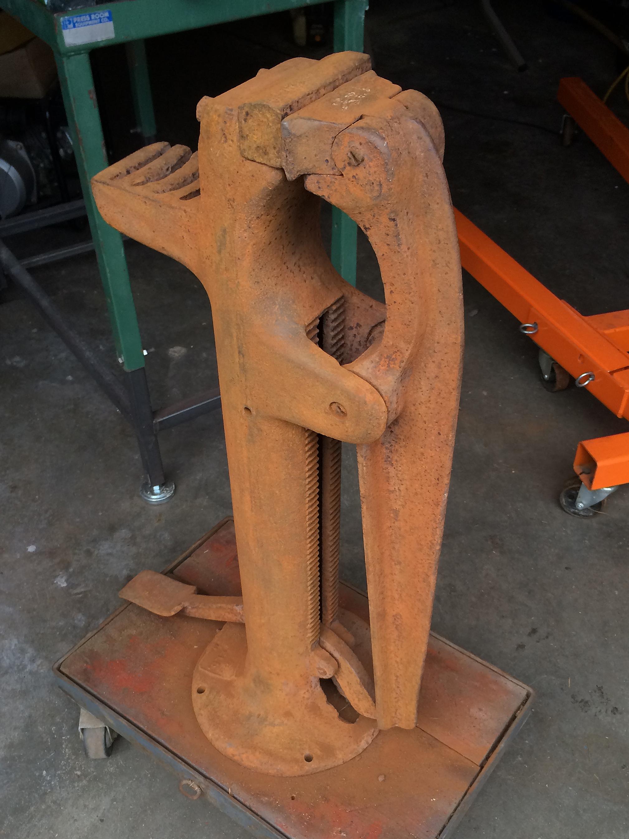
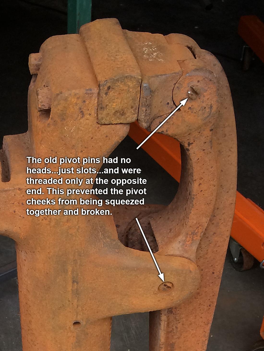
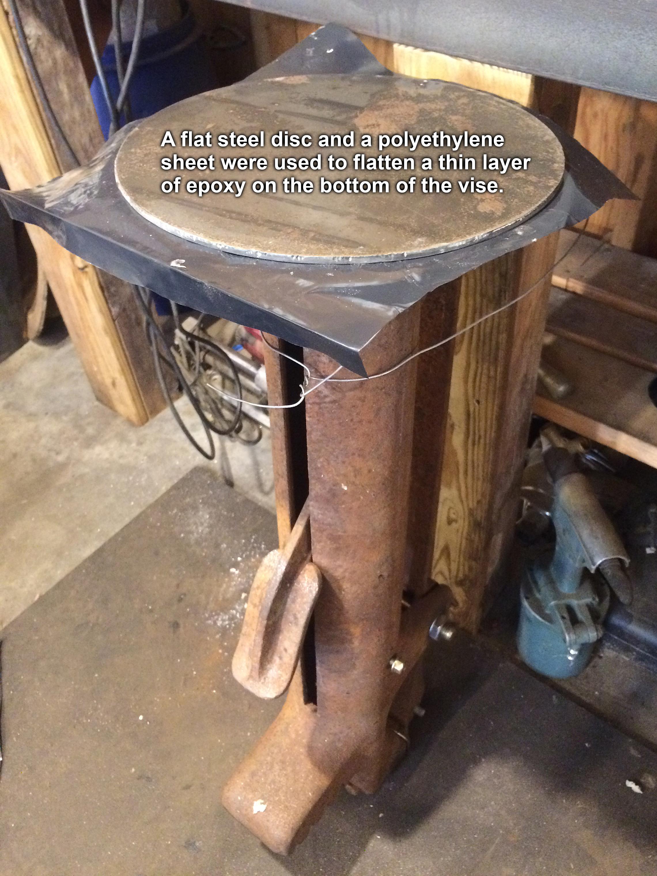
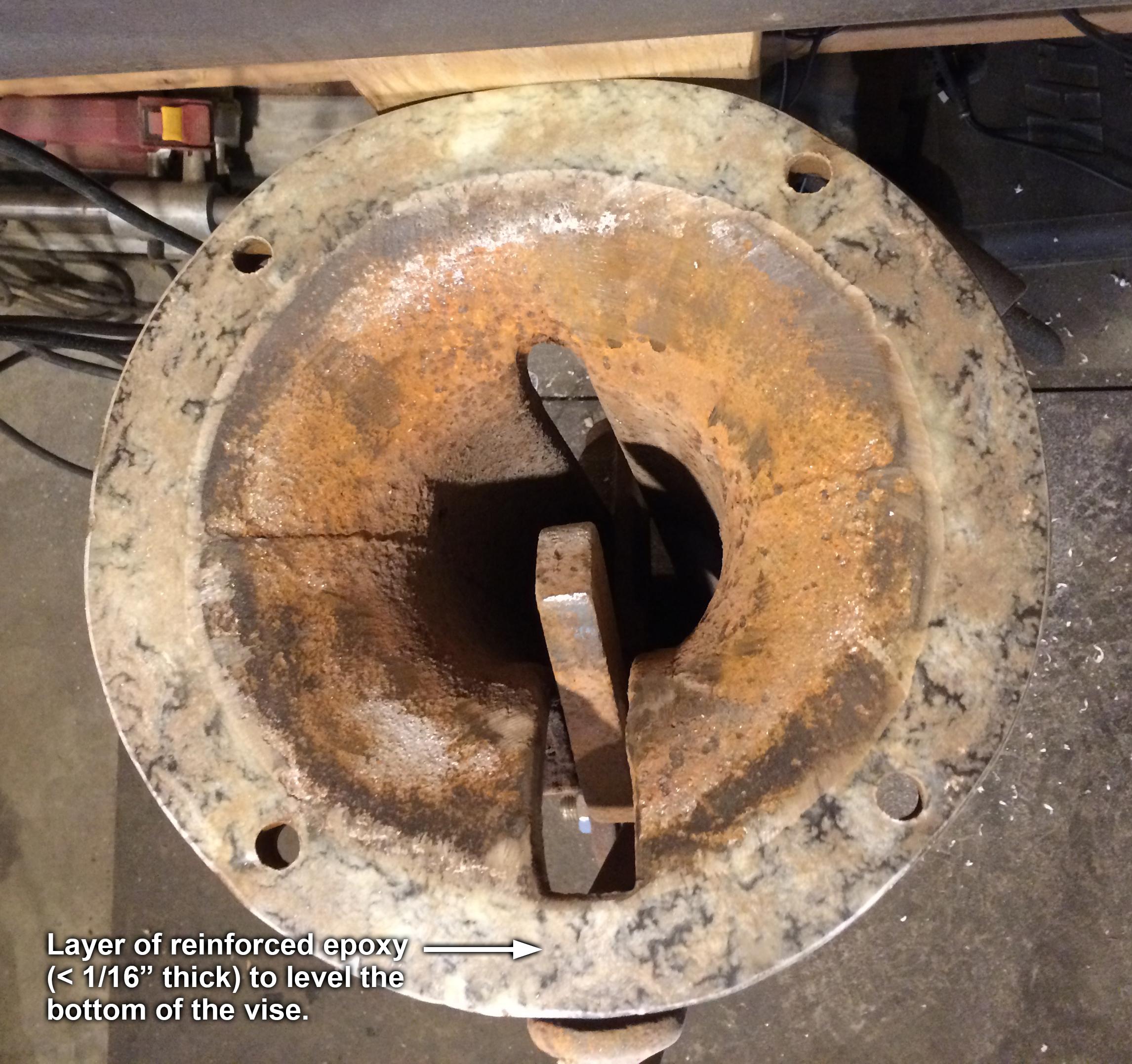
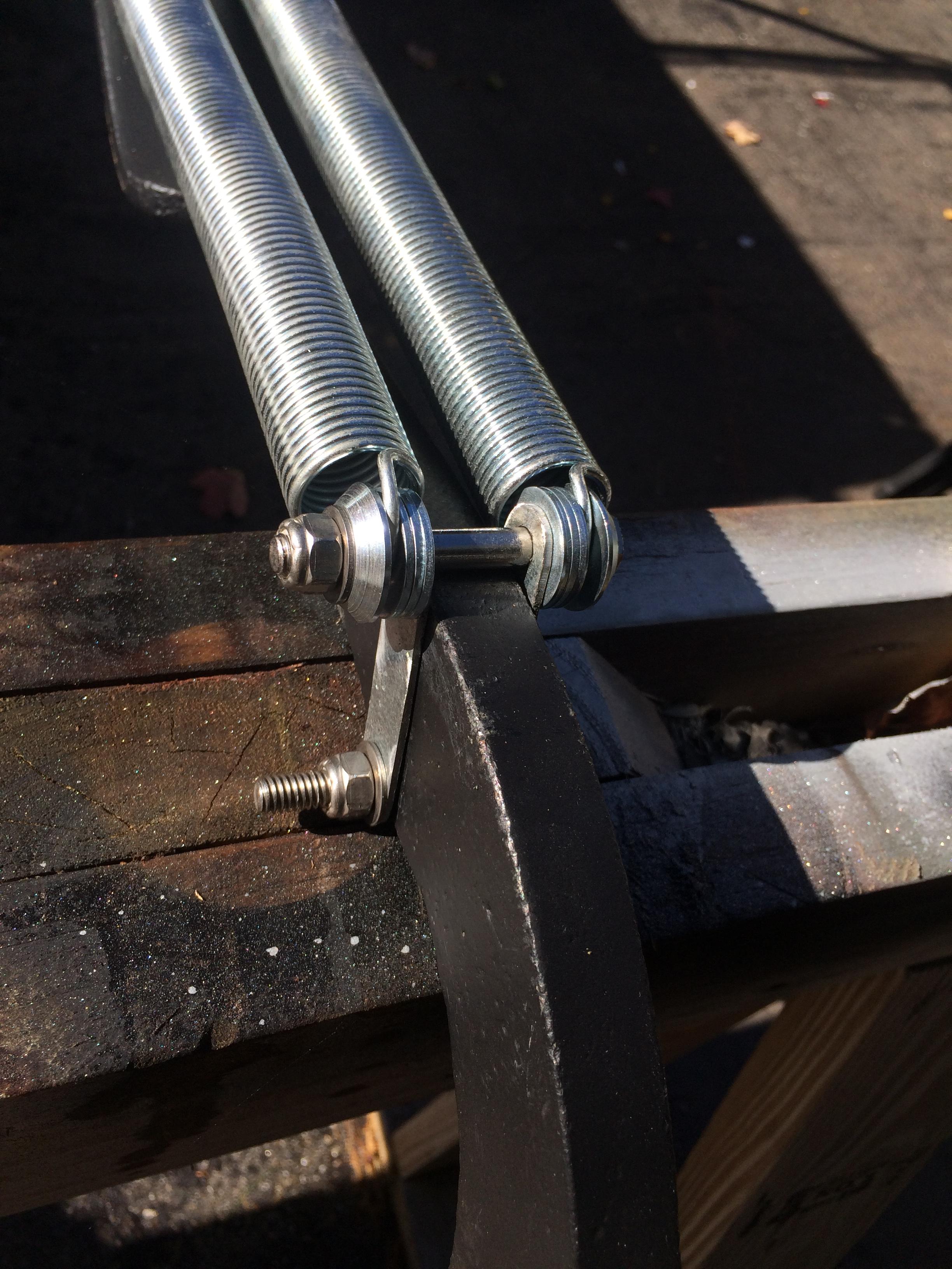
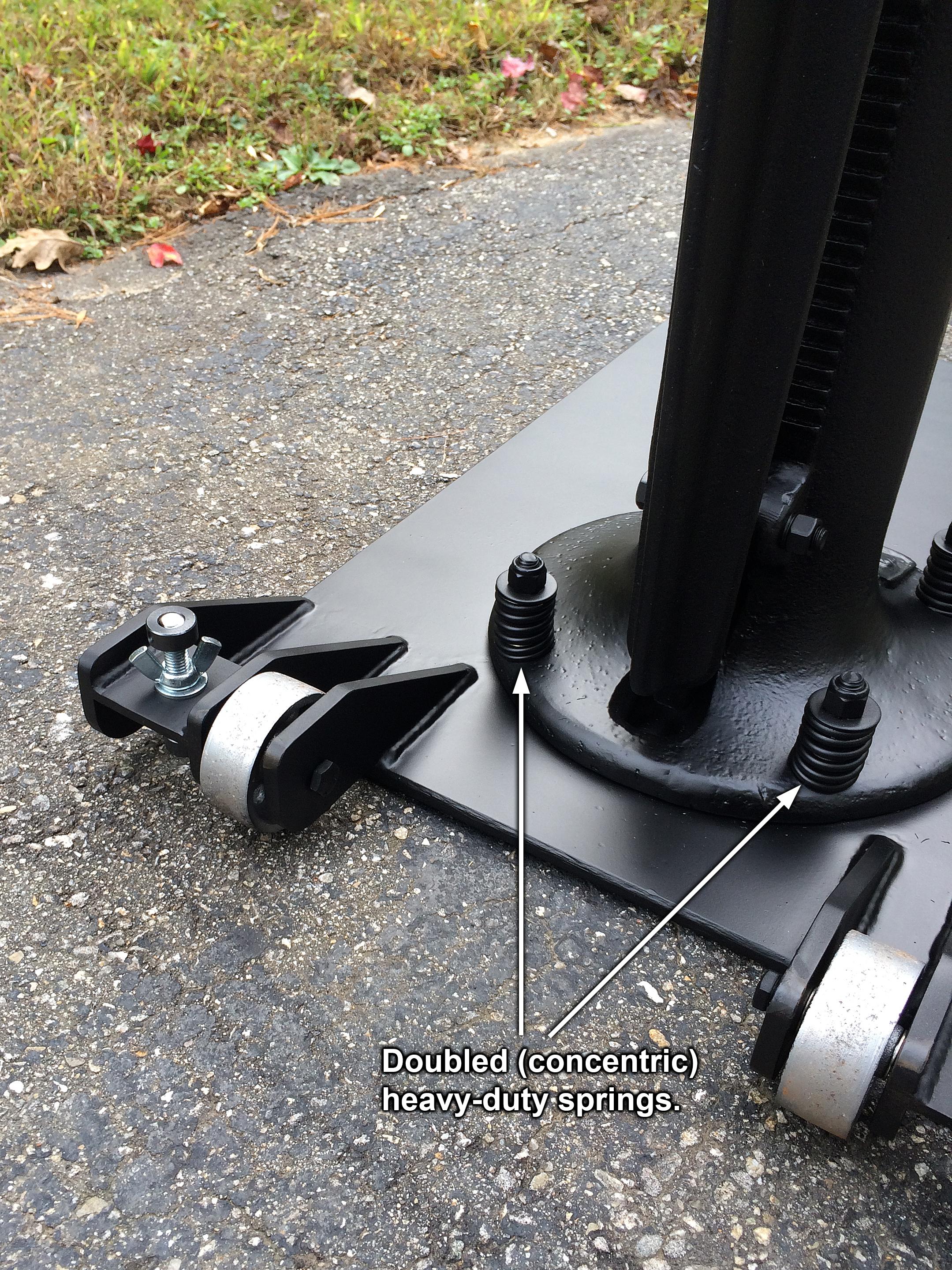
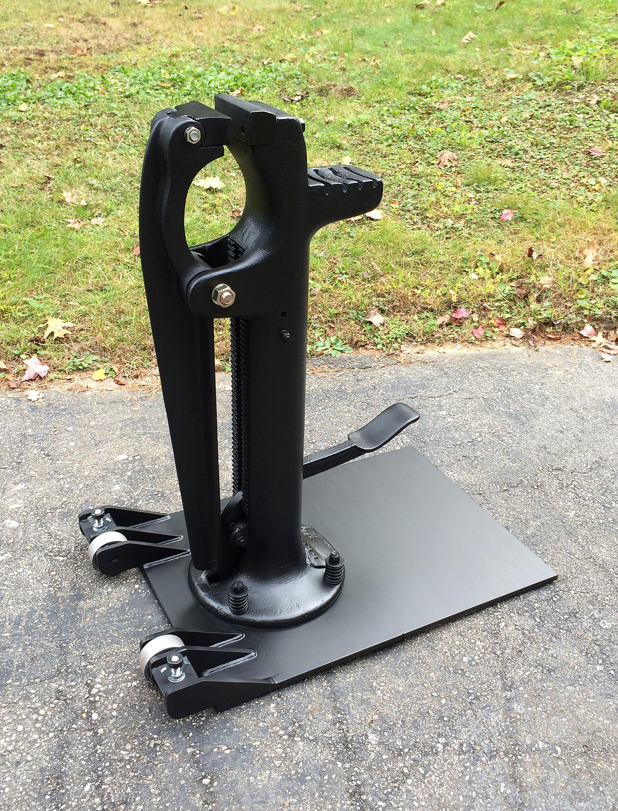
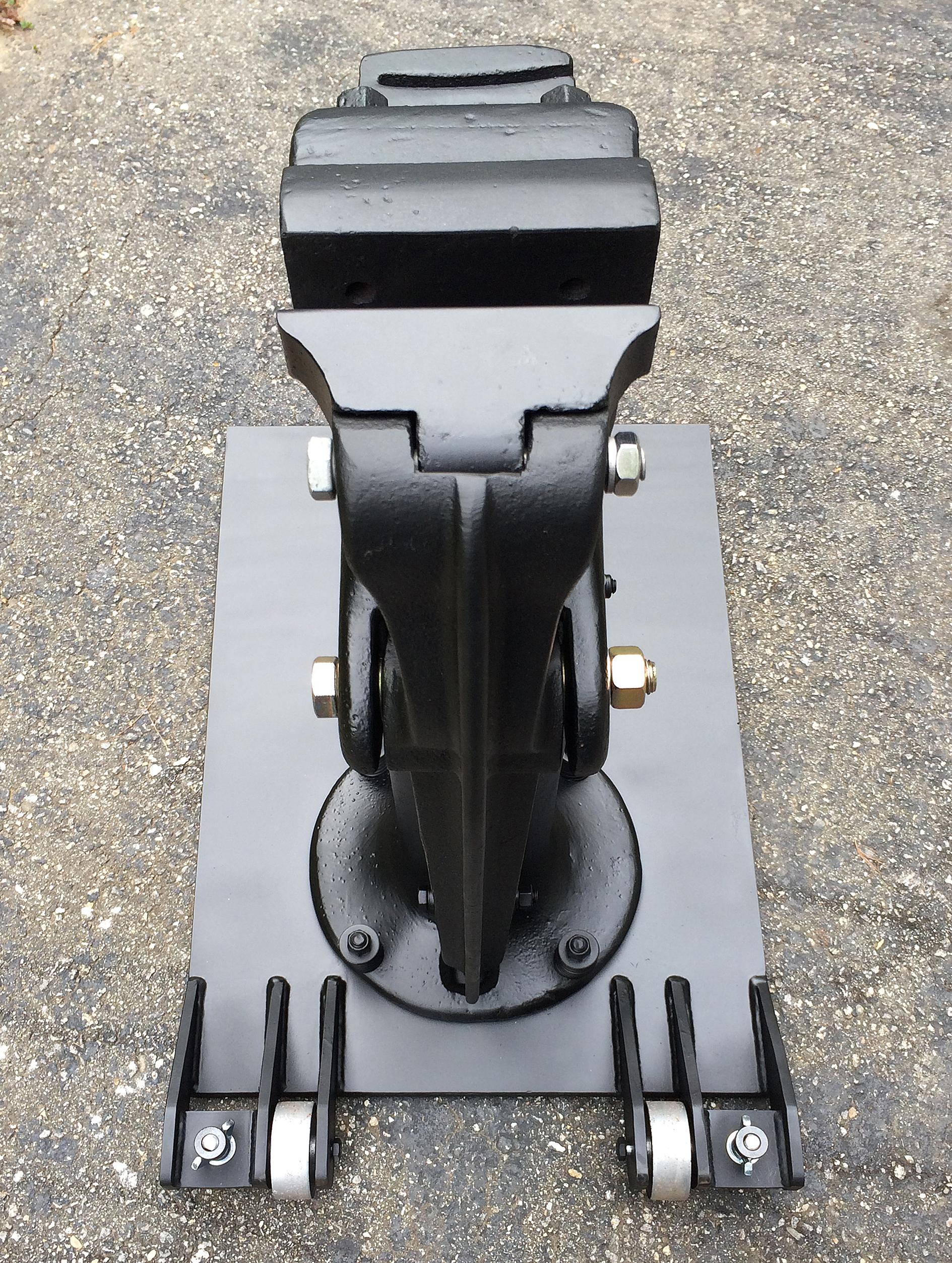
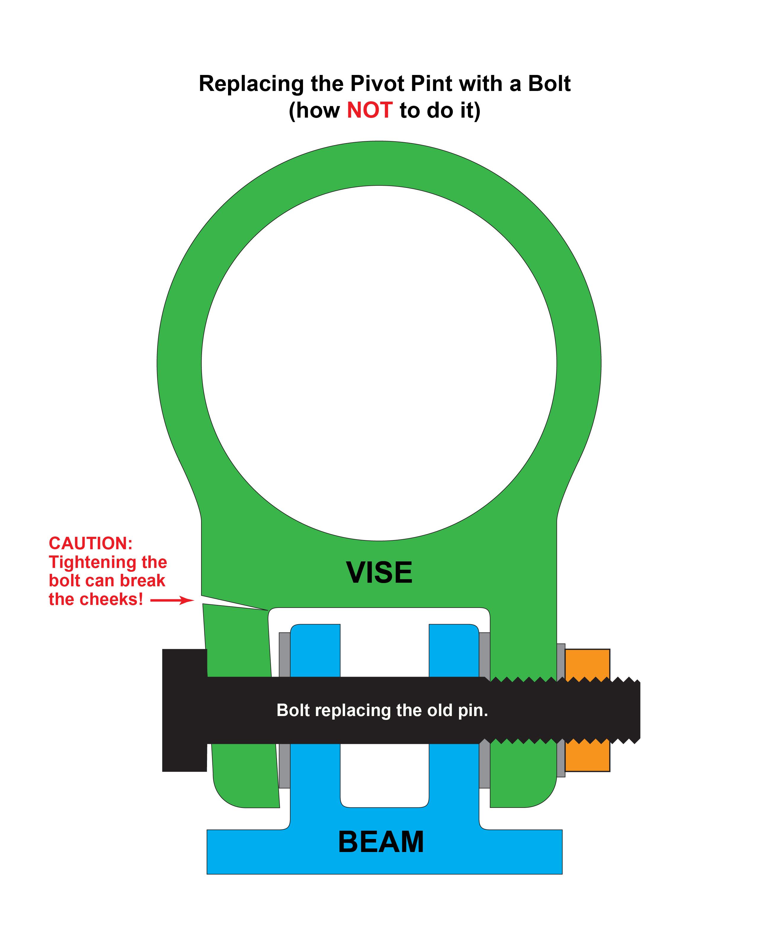
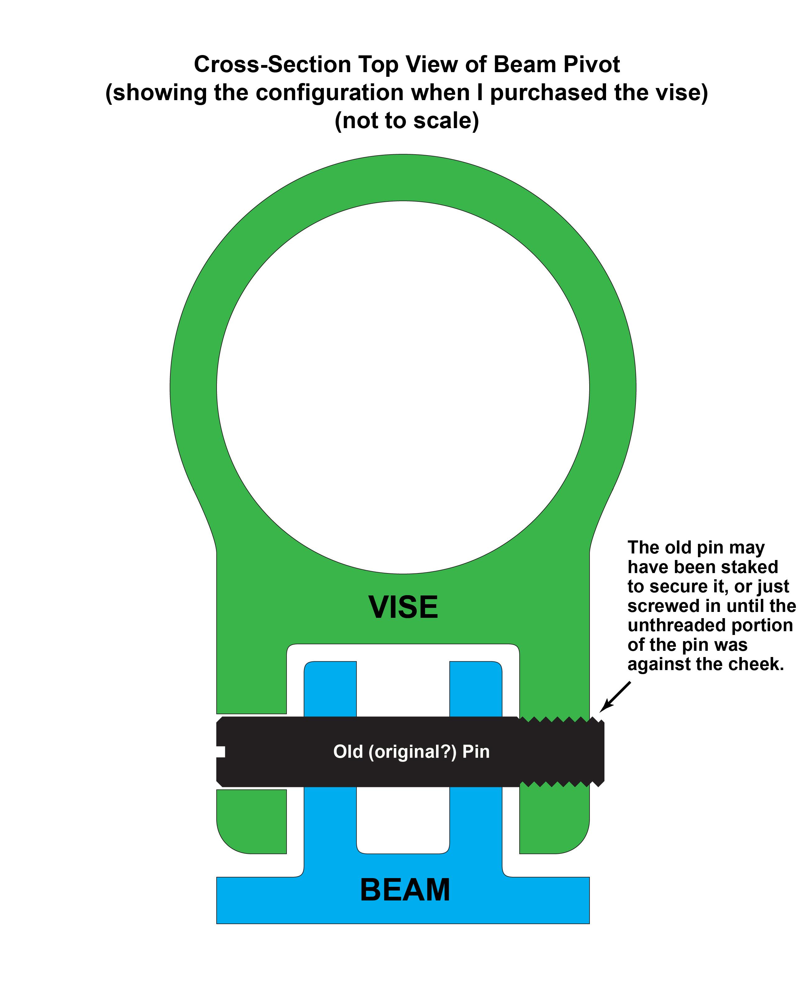
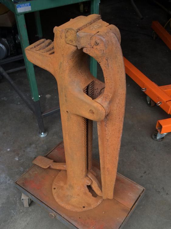
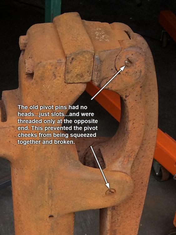
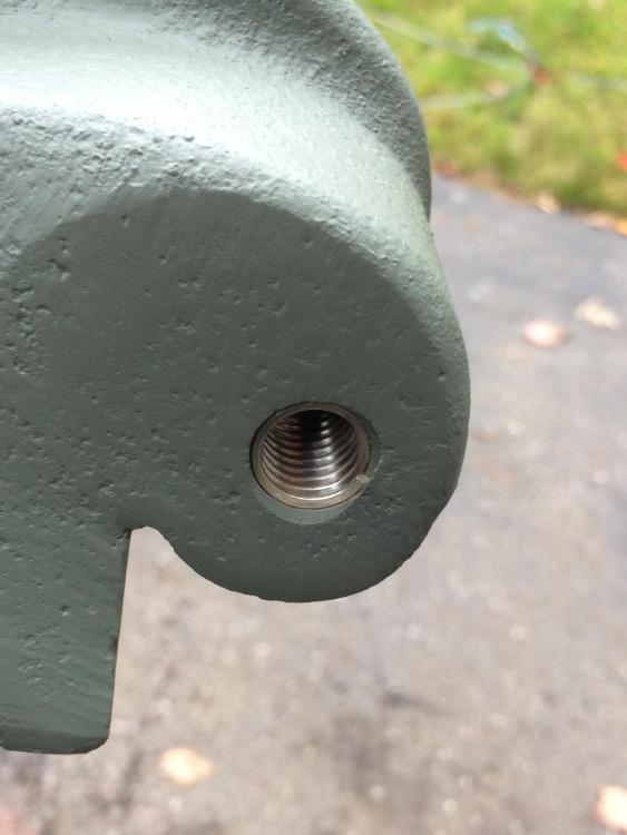
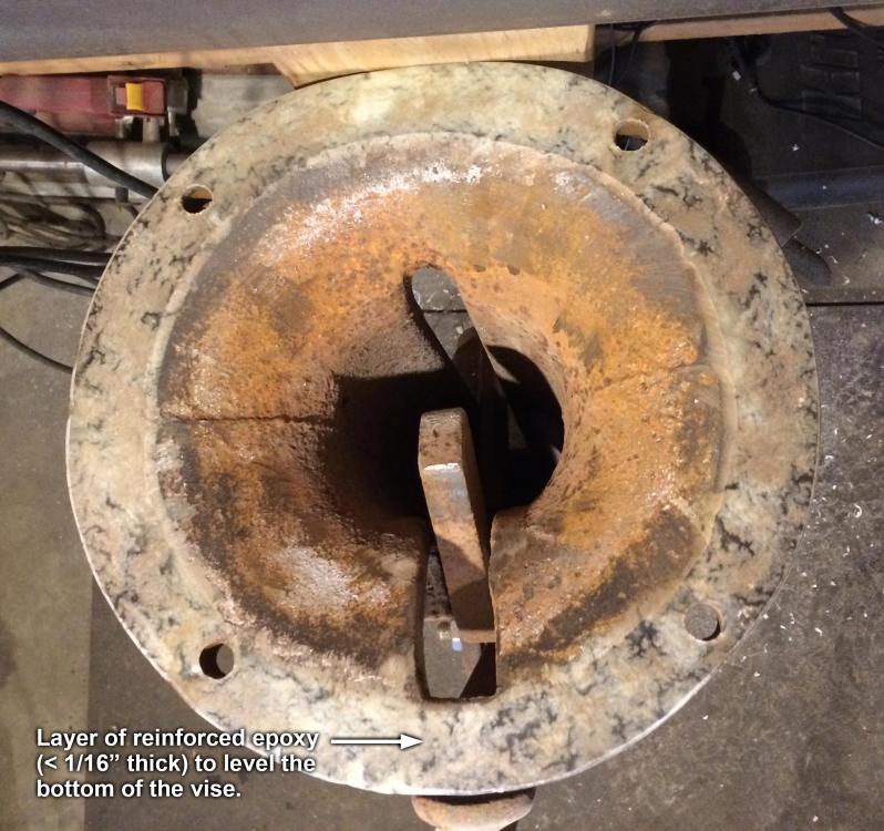
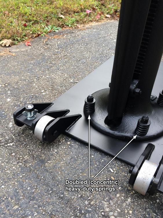
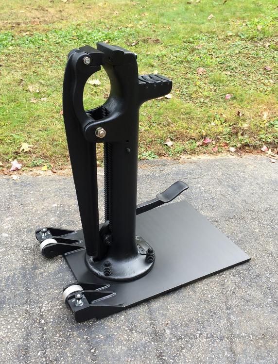
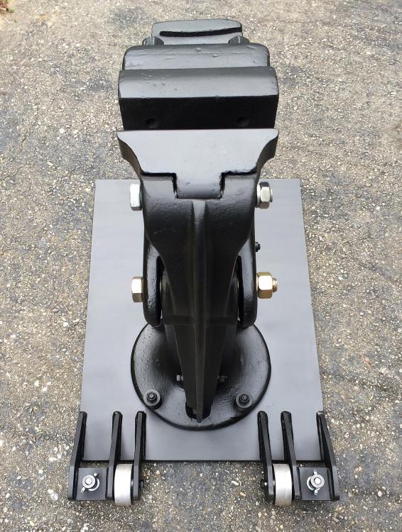
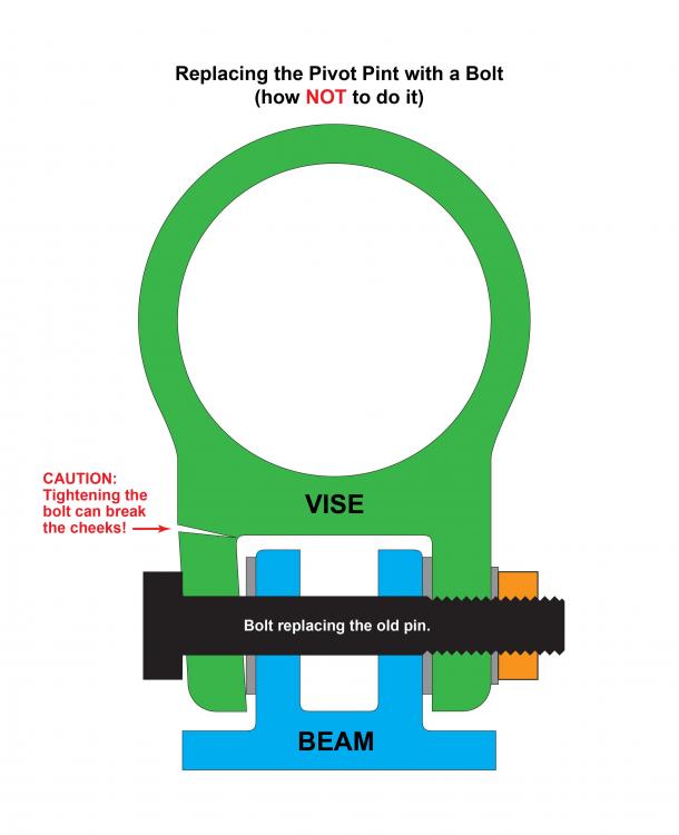
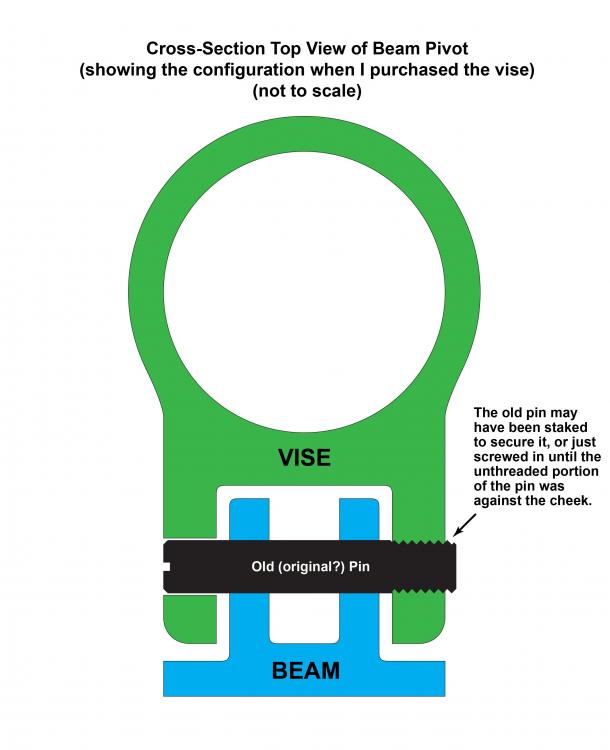
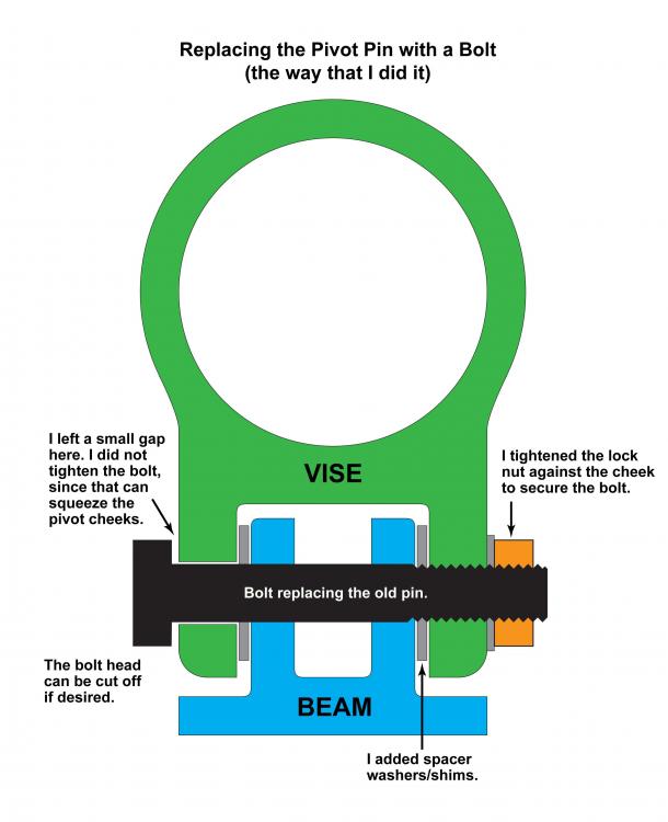
A few weeks ago I decided to rejuvenate an old B. B. Noyes farrier’s foot vise and construct a movable base for it. I’ve included lots of details and photos, so I hope no one gets bored. I picked up the vise a while back for an even hundred bucks (US). Even though the vise needed some TLC, it had good “bones.” In other words, there were no breaks, repairs, cracks, or deeply rusted areas, and the jaw faces were still in good shape, so I thought it might be worth some effort to put it back into operation. It was missing the adjustable-height upsetting block (which would also make an excellent depth stop), but from what I’ve seen, they are usually missing that part, and I figured that I could machine a replacement when I have time. There was also some wear in the grooves in the calking block, but since I'm not a farrier, that was not of much concern to me. I should mention that one of the jaw inserts (the fixed one) is a very hard steel that was unimpressed by the application of one of Mr. Nicholson’s files, while the other insert (the one that swivels on its pivot pin) is made of cast iron. This was apparently by design, since I have seen other foot vises with the same combination of steel and cast-iron jaw inserts. The vise originally was available with several different jaw inserts, but I only have the straight ones. Both the fixed and the swivel jaw inserts can be mounted in two positions, for four possible combinations of jaw curvature and height relative to each other. A bit of research showed that people have used all four combinations on these Noyes vises and the similar Wells vises. Note that the mover's dolly that the vise is sitting on in the photo below is NOT the base that I fabricated for it. Here are some of the key steps involved in the rejuvenation process: First of all, the pivot pins for the beam, jaw insert, and foot pedal were all stiff from decades of neglect and rust. I decided to remove and replace them, not only to free them up and make up for wear, but also to allow the insertion of spacer washers/shims to keep the jaws and beam centered and to allow better access to the inside of the vise for the installation of a new return spring to raise the foot pedal. The old pivot pins were threaded at only one end and had a screwdriver slot at the other end. These pins were firmly rusted in place, and since the pins were headless, I could not apply enough torque to loosen the rusted pins, even after a liberal soaking with rust buster. So, I resorted to a different method...one of several possible methods for that situation that have served me well over the years...which involves careful incremental drilling of the threaded end of the pin to leave a very thin tubular “shell” of the threaded portion, which I then “peel” away by gently tapping around it with a small-diameter round punch that has been ground on the end to form an oval-shaped chisel point with a sharp leading edge. This worked great for two of the pins. I was able to remove the pin for the beam pivot and the pin for the foot-pedal pivot with no damage whatsoever to the original female threads in the cheeks. However, the pivot pin for the swivel jaw insert was recalcitrant and refused to submit to this method of persuasion. Two types of easy-outs were of no use either. This situation required escalating the removal effort to the next level, which involved drilling the threaded hole to a larger size to completely remove the remnants of the pin, tapping new threads in the enlarged hole, and then installing a Heli-Coil insert, as shown below, to bring the threads back to their original size (photo taken after vise was primed). The next step was to true-up the bottom of the vise so that it would lie flat against the planned base plate. I must say that this vise certainly does NOT represent the acme of precision casting. The vise was pretty wobbly when set on the base plate, since the bottom was probably out-of-flat by at least 1/8 inch. I touched it up with a sanding disk in an angle grinder to the point where it was very close to flat, but rather than tediously chasing the elusive goal of perfection with the contact-transfer method using an indicator fluid or other medium, which would have involved dozens of small adjustments, I opted to finish the flattening by using some epoxy mixed with a tough fiber filler. I applied a thin layer of the thickened epoxy on the periphery of the bottom of the vise, laid a sheet of polyethylene over it, and then laid a flat, round steel plate on top of the polyethylene, with some extra weights stacked on top of the plate to squish the excess epoxy out, as illustrated in the photo below (which is not showing the extra weights). The following picture shows the flattened epoxy after cleaning it up around the edges. The epoxy layer is quite thin...probably no more than 1/32" thick on average and nowhere greater than 1/16" thick. This made the bottom of the vise VERY flat, with no wobble whatsoever when placed on the new base. Next, I wire-brushed the vise, primed and painted it, and began installing the components. I used partially-threaded hex-head machine screws/bolts to replace the old pivot pins. Note that for each pivot, one cheek is threaded and the other is not. Also note that I was very careful NOT to tighten the bolts where they go through the pivot cheeks. In fact, I left a little space under the heads of the bolts. If you use bolts with heads on them and tighten the bolts a little too much, it could break the cast-iron pivot cheeks, and I’ve seen a couple of these old vises with welded or brazed cheeks, probably for that very reason. The old pins were threaded at only one end and had no heads on them and therefore could not possibly squeeze the hinge cheeks together and break them. Because of the rust and the pivot-removal process, I could not tell if the old pins had been staked in place or if the pins were just screwed in until the unthreaded portion of the pin was up against the cheek. To prevent the new bolts from rotating, I simply installed a lock nut on each bolt. The following three drawings of the beam pivot represent 1) the pin that came with the vise when I bought it; 2) how I replaced it with a bolt; and 3) a caution about what to avoid if you work on one of these vises. The bolt heads were not necessary, but I left them on because I wanted to be able to remove the bolts easily for future maintenance. If I were going for a museum-quality restoration (assuming that this vise was in its original configuration when I bought it), I would have cut off the bolt heads, cut a slot at that end of the bolt like the old pins had, and ditched the lock nut. I installed spacer washers/shims in the beam pivot and the foot pedal pivot to help keep the beam and pedal centered while in use. I’m not sure if it originally had such spacers, but if not, I think it should have had them. I installed a pair of return springs on the foot pedal to raise the pedal (see photo below). This took a bit of experimenting to come up with the right spring length, spring rate, and a mount that would work correctly on the pedal (and not slip out of place) without having to modify the pedal. It worked out well. The springs raise the pedal to the correct at-rest height and seem to have just the right amount of tension. Note that I was trying to plan ahead for eventually installing an upsetting block (or depth stop, if you prefer), and using twin springs left a space between them that should allow the mounting bolt for the upsetting block to pass between the springs. No spring is required to open the vise jaws, since gravity will take care of that as long as the foot pedal is raised. Now it was time to build the base for the vise. I got a good deal on a slab of 1/2” plate from a local supplier’s scrap pile and found the rest of what I needed in my own “surplus” pile. I installed two cast-iron wheels, as well as two home-made leveling feet to compensate for any unevenness in a floor. I only plan to use this vise on concrete or asphalt, so I kept the wheel size fairly small, which also helped make the base more compact to fit inside my slowly-evolving mini-shop. Even though I flattened the bottom of the vise with a bit of epoxy, I was still leery about over-tightening the cast-iron vise base flange against the new steel base plate, so I mounted the vise using eight heavy springs, as shown below. It might look like there are only four springs, but there is a second set of springs inside the other springs (i.e., concentric double springs). These heavy springs limit the force holding the vise to the base to what I consider a safe level to avoid possibly cracking the cast iron, but there is still more than adequate force to keep the vise securely mounted. The vise doesn’t move at all on the base when in use. Following are two more views of the vise. All in all, it works great, but there are still a few improvements that I might make to the vise. For example: I would like to make some removable steel jaw liners, and maybe a set of brass or copper liners. I would like to install a thick steel plate over the calking block, partly because there is a good deal of wear in the calking block grooves, and also because I think that a flat surface would be more useful for my own purposes. I will try to figure out a non-invasive way of installing the plate, since I would rather not modify the vise itself. I’m also thinking about adding a small tool rack to each side of that plate, which could double as a handle for moving the vise around. Al (Steamboat)


-
Excellent work on the stand, and I like the fact that you've built in so many sturdy mounting points for possible attachments/accessories. Do you have any specific add-ons or connections with other equipment in mind? Al (Steamboat)
-
Pit method charcoal making
Steamboat replied to Beavers's topic in Solid Fuels: Coal, Coke, Charcoal, Wood, etc
If you feel like doing some reading, here is a link to a publication on the Vermont Archaeological Society website. Chapters 5 and 6 deal with the history of charcoal making. You may find it quite interesting. https://www.vtarchaeology.org/publications/200-years-soot-sweat/ Al (Steamboat) -
I think you're on to it. Spirals like these are commonly used as feed augers, such as used on pig farms. Al (Steamboat)
-
Thanks, Jeremy. I'm trying to decide on the best compromise between the appearance of the mesh itself, its relative rigidity, and the visibility of the fire through the mesh. I do like the looks of the mesh you used. I have four (and eventually five) screens to make for our old-house project, so I think it might be worth ordering a sample set of meshes and do a side-by-side comparison. Al (Steamboat)
-
Really nice screen set! I had asked you this before, but I guess you missed it: What woven wire mesh size are you using, and do you have a preferred source for your woven wire? I'm planning to make a few fireplace screens in the near future. Al (Steamboat)
-
Show me your sales or demo booth
Steamboat replied to Glenn's topic in The Business Side of Blacksmithing
Glad the fair was successful for you, Das. You have an amazing selection of cool items! A couple of fabric wrinkle-resistant shower curtains might make a handy backdrop that you could easily adjust to the display area size as long as you have telescoping curtain rods or something similar. You could also clamp a couple of small LED spotlights on the frame for a bit of dramatic lighting. Al (Steamboat) -
What did you do in the shop today?
Steamboat replied to Mark Ling's topic in Blacksmithing, General Discussion
Very graceful-looking leaf, Ted. It looks like the new swage tool should come in handy for other tasks as well. Al (Steamboat) -
What did you do in the shop today?
Steamboat replied to Mark Ling's topic in Blacksmithing, General Discussion
Beautiful work. I'd definitely keep that one too. Al (Steamboat) -
Thanks for the photos. It's a nice neat build and it appears to be very well thought-out and organized. Good job! Have you done any test firings yet? Or are you waiting until you secure the rear brick doors? It doesn't look like the sliding firebrick doors are being stressed when they are being pushed in/closed, since a large area of the attached steel angle is pushing against them, but when being pulled out/opened, the two screws through each door appear to be carrying the lion's share of the pulling effort and might create a couple of stress points, although those stresses could be mitigated in a few different ways. As you alluded to, I imagine that the soft brick doors should probably last long enough to do some forging and give the doors a good test. If they do happen to crack, at least it should provide some data. You would probably learn more about the cause of a failure and whether or not it had anything to do with the way the bricks were connected to the linkage, which could guide possible design modifications or perhaps only a change of refractory material for the doors. It will be interesting to see it in action. Al (Steamboat)
-
DWH, great job on the forge! I like the linear actuators to adjust the door openings. I might even consider adding a couple of 12V or 24V actuators to my own gas forge if I could find a couple of them at what I consider an affordable price, since I already have a firebrick-door-holding setup that would easily lend itself to such a modification. I'm guessing that actuators similar to the ones you're using might run in the $300-plus (USD) retail price range each. I hope you got a good deal on them on CL. The air curtain is a nifty feature. So far, I haven't had an issue with dragon's breath from my normally-aspirated gas forge, but there are still some occasions when I would not mind being able to get a little closer (in comfort) to view the state of the metal inside. Even though I can't see all of the details of the forge up close in the video, my perception is that the workmanship is really good! You should post pictures of the build process if you have them! As Latticino suggested, there are always some whistles and bells one could add, and judging from what you've done so far, it would not surprise me if you soon post an updated version of the forge with some of those features added. I can't tell from your short video how the burner is oriented. Does it impinge directly on the floor of the forge, or does it have more of an angled or tangential entry? Very cool! Al (Steamboat)
-
What did you do in the shop today?
Steamboat replied to Mark Ling's topic in Blacksmithing, General Discussion
Oh, I know, Das. I was just ribbing you a bit. If you can make and sell 50 of them, all the better to finance your other projects. Al (Steamboat) -
What did you do in the shop today?
Steamboat replied to Mark Ling's topic in Blacksmithing, General Discussion
I think it looks great. Interesting combination of the rasp and cable damascus patterns. Das, you've made another very cool critter. I hope your sales adequately support your scorpion habit. Ted, nice smooth work on the hooks, and I like the embedded magnet idea. 4Elements, that is an elegant-looking piece. Your wife should be pleased with that. Al (Steamboat) -
What did you do in the shop today?
Steamboat replied to Mark Ling's topic in Blacksmithing, General Discussion
Sounds like the ergonomics are fine...and they're great looking. Al (Steamboat) -
Ausfire, I see that Jennifer has posted her basket twist video. I had included a link to this video in one of my earlier postings in this thread, but I guess you missed it. It's definitely worth watching. I'm planning to try her mandrel method soon. I've got the steel...just need a bit of free time. Al (Steamboat)
-
That should make a perfect quench tank after you've added a sturdy base and a lid. I'm planning to make a new one myself, since all I have now is some PVC pipe as a temporary solution. I'm planning to make some kind of basket that could lie at the bottom of the tank that's attached to a rod that extends to the top of the tank, so that if I drop anything into the tank I can just grab the rod and lift out the basket with the part instead of having to reach down into the quench solution (if I could even reach to the bottom). Also, that was a good suggestion to check welding gas suppliers for tanks that failed the hydro tests. I will check with the outfit that I've been getting my welding gases from for the last ten years. Even if they might normally sell their old tanks as scrap, I'm guessing that they might give me an old bottle or two as a bit of lagniappe. Al (Steamboat)
-
What did you do in the shop today?
Steamboat replied to Mark Ling's topic in Blacksmithing, General Discussion
Very nice looking tongs! I like the lightly beveled edges...nice touch. I can't tell for sure, but is the shape of the handles designed for a southpaw? Al (Steamboat) -
FWIW, I should add that your lapping tool's tip could be swiveled 90 degrees to use either the two-prong tip to lap/grind the valves on cars like Model T Fords that had two holes in the top (or "head") of the valve, or or a flat tip that was probably for lapping valves on other engines that had a slot in the valve head instead of two drive holes, so I'm guessing that it was probably a 'universal' valve lapping tool, which may have come with other tips that could be switched to fit other valve configurations. Whew! That's about as much valve-lapping esoterica as I can come up with at the moment. Al (Steamboat)
-
You're welcome. I can't include the link, but if you go to the USA ebay, you can search for "antique ford valve lapping tool" (without quotes) and something similar to yours should come up, unless it's been sold by the time you try searching for it. Al (Steamboat)
-
I think that what you "probably" have is an antique automotive valve lapping tool. Many antique automobile engines had valves with two holes in the top. A lot of different hand-operated valve lapping tools were manufactured that had two prongs that fit into the holes in the valve. The idea was that after removing the valve springs, you would apply lapping compound (grease or heavy oil with an abrasive mixed in) to the valve face and seat, and then you would use the lapping tool to rotate the valve back and forth, periodically re-applying the lapping/grinding compound as needed. The lapping compound came in different grits so that you could get a rather fine finish at the mating surfaces. It didn't produce as long-lasting of a result as, say, a proper three-angle valve grind, but it did the job. There were spiral models, geared models, hand-crank models, and even plain wooden sticks with suction cups and two-prong attachments. I'll see if I can find a picture of a spiral model, which is probably the oldest type, but in the meantime, here's a link to a picture of a geared model that would do the same job. http://www.agcoauto.com/content/plugins/p17_image_gallery/images/64.jpg You can still buy hand-crank valve lapping/seating tools that come with a two-prong adapter. Al (Steamboat)