Steamboat
-
Posts
261 -
Joined
-
Last visited
Content Type
Profiles
Forums
Articles
Gallery
Downloads
Events
Everything posted by Steamboat
-
Most people in this area heat with fuel oil, which is not cheap, but that means that there are lots of old burners that can be had for next to nothing, and sometimes free, so if I ever get to the point of building an oil-fired forge, I should be able to build one for very little expense. It's several notches down on the bucket list, but who knows? Maybe someday. Thanks for the positive feedback on the house. I really enjoy working on old houses. This one was built somewhere between 1797 and 1805 as nearly as we can tell, and it was originally the parsonage for the town's "meeting house" (Congregational church, in this case), which was built in the 1780s. Al (Steamboat)
-
Yes, Frosty, it does seem that one could get quite creative when it comes to burner shapes. As to fuel oil burners, we've been heating two houses with fuel oil for the past 10 or 11 years, and I've often looked at the oil burners and wondered how they might adapt to a forge, but that's as far as I got. Too many other projects going on to take the time to research it. Frosty and Ted, here's a link to a few photos of our restoration-project house, including one of how it looked when we bought it, another of how it looked after most of the major structural and exterior work was done, a photo of working on the foundation, and a picture of the basement stone walls after most of the work was done on them. The basement stone walls actually look better now, after some additional pointing was done and after the mortar turned a consistent light gray. The mortar looks dark in this photo because it had recently been sprayed with water and was only partially dry. You can see that there are some pretty large stones here and there. I've got better and more recent photos somewhere, including some images of the exterior foundation, where we really made the effort to get a nice fit in the stonework, but this should give you a rough idea of the scope of work. http://todacosa.com/campobello/images/foundation-work.jpg Al (Steamboat)
-
I'm not trying to promote the use of hard fire brick for a ribbon burner head, and if I ever get around to building one, it would be a while before I can get to it. If I were to construct a ribbon burner, there's a good chance that I would make a casting, since I like casting things and I could make pretty much any shape I envision, but I prefer to keep the options open and consider all ideas, since the designs and ideas that have been put forth on this forum and other sources are not necessarily exhaustive. As to securing a hard firebrick burner head to a steel plenum, I haven't given it a lot of thought, but one possibility that just popped into my head might be to cut a groove/dado on all four sides of a brick, slide the edges of a two-part plenum into those grooves, screw the plenum halves together, and seal the grooves with refractory cement, high-temperature gasket material, or whatever. One advantage might be that you could make a few extra burner heads and quickly replace them if they are damaged. Is this a good idea? Maybe, maybe NOT, but I'm sure that with more thought, other possible approaches would emerge. As to whether or not the seal between the head and the plenum would hold up with usage, I don't know the answer to that either, but the same question can be asked about a cast-in-place burner head. You are still mating two different materials, each with its own rate and amount of expansion and contraction with heating and cooling cycles. Any differential will need to be tolerated somehow, either by the materials themselves, by the design of the burner, or both. Otherwise, cracks could develop, or the seal could loosen up. Is a cast-in-place Kast-O-Lite refractory burner head tolerant enough to maintain a seal over time? Again, I don't know, although I suspect it would depend on multiple design factors. A good topic for someone to start would be "How is your cast ribbon burner holding up?" A possible subject for research might be to look at commercial burners of various kinds that use some type of ceramic/refractory material for a burner head and note the ways that the burner head is secured in the burner. I don't have the time to pursue that line of research...too many other projects...but maybe someone would find it of interest. It might be worth looking at other shapes of burners, too, such as those with round ceramic burner heads that have multiple nozzles. You might be able to achieve the same effect as a rectangular ribbon burner by using a series of, say, four cylindrical burner heads, each with multiple nozzle holes arranged in a linear array. The idea of a round burner head seems to open up the possibility of some kind of screw-down method for securing the head to a steel plenum. Maybe make a cylindrical burner head with a hat-shaped cross-section and use a threaded ring to tighten the burner head down against a gasket? Just thinking out loud...fun to speculate... Foundation pictures coming...probably later today. Al (Steamboat)
-
I have a contractor friend who specializes in custom fireplaces. He has a real knack for splitting stones and getting them to break just the way he wants them to break. Sometimes I can tell how a stone will break by looking at some tell-tale smaller fractures, chips, or facets and trying to split parallel to those, but some stones have such an amorphous structure that they don't really have a specific natural cleavage that I can discern, which isn't necessarily a drawback, because those will often cooperate by splitting along and straight down under the line of wedges. I've found that the longer the wedge line and the closer together they're spaced, the more predictable the split will be, as you might expect. It's possible to place wedges on opposite sides of a stone in line with each other and going back and forth from side to side with the tapping sequence until it splits, and with luck it will split along both lines of wedges. Or you can wrap the wedge line part way or all the way around a rock if you have access. I'm not an expert at it, but I've done some pretty clean splits. Some of the granite foundations in the big old houses and mansions around here are quite impressive. Those masons knew what they were doing. As to photos of the house restoration process, I'll plan to post a few links tomorrow so you can see a couple of "before" and "during" photos. The house is still a work in progress. Most of the heavy structural work is done and the exterior is mostly finished, but there is still a lot of interior work left to do. Al (Steamboat)
-
That's the first time I ever split rock from a cliff face. Most of the splitting that I've done has been for foundation work and for a couple of fireplaces. For example, my wife and I are gradually restoring a house that is more than 200 years old, and we had a huge amount of foundation work to do on it. The original foundation was loose-stacked stones with clay pointing, and previous owners tried to "fix" the broken-down areas with mortar, but did a poor job. We had to remove all of the old mortar, re-stack many of the stones that were out of place, and split dozens of stones to get them to fit correctly, and all this while the house was up on jacks. I did have help jockeying the heavier stones around. We did a "proper" mortar job, as well as a reinforced, out-of-sight, below-ground "battered" wall against the foundation, plus a whole bunch of other foundation and basement stuff too numerous to mention here. Anyway, we managed to maintain the basic original appearance, keep 95% of the original stones, and ended up with a strong and dry basement, and dry basements in old houses in Maine are quite rare. I also did some rock splitting (and 6-inch diamond drilling) on ledge rock when we installed the shore posts for our dock. Also a bit of patio fieldstone work that I had forgotten about until now. Splitting rock is actually quite fun (all except for the drilling). It's amazing how a repeated series of relatively light taps on wedges can split a stone the size of a Volkswagen, although I personally have never split one that large. Al (Steamboat)
-
Frosty, when I drilled that brick, I drilled it with a small piece of sacrificial plywood under it to reduce the "breakthrough" effect and was very careful to apply only the slightest pressure when nearing the bottom side of the brick. That brick drilled quite easily, with very little pressure applied. I believe that I could duplicate that in a video if anyone is interested. The bottom breakout was larger in the 70% alumina brick, but as mentioned, that brick seemed more granular and less homogeneous than the other two. This is slightly off-topic, but on the subject of drilling with carbide masonry bits, here's a stairway that I built last year, which required quite a lot of drilling (with a hammer drill) and wedging to split off some large granite slabs to make room for the stairway. It was not a comfortable working position, and it was a four-hour drive from my house, so I had to make do with some tree limbs and rocks for a "scaffold." I pre-built the stairway in my driveway, disassembled it, and installed it piece by piece at the location you see. I had to drill more holes in the side of the cliff for anchor bolts for chains to suspend part of the stairway. http://todacosa.com/campobello/images/side-view-of-stairs-looking-up.jpg http://todacosa.com/campobello/images/stairway-looking-down-from-top.jpg http://todacosa.com/campobello/images/a-few-feathers-and-wedges-for-splitting-granite.jpg Al (Steamboat)
-
Ted, it would be interesting to know what manufacturer and model of hard fire brick you were having difficulty drilling. I've never had an issue with cutting or drilling any of the ones I've used over the years for stoves, fireplaces, a glass furnace, and more recently forges, but I can't claim to have used them all. You might also try drilling it again with a fresh high-quality masonry bit and experiment with drill speed and pressure, as I recall Frosty suggesting. If the speed and pressure aren't close to optimum, the bit won't drill effectively. As to the material for a ribbon burner head, I wasn't necessarily suggesting hard fire brick (I was just responding to the fire brick drilling issue), although as I have no serious experience with ribbon burners I'm not yet ready to categorically rule it out as a material for the burner head. There are certainly hard fire bricks that can remain structurally sound in temperatures achieved in gas forges, so I don't think that should be an issue. The specification sheets for various hard fire bricks can provide data regarding their performance at different temperatures. I've used Kast-O-Lite 30 refractory to make a number of castings, and I've discussed Kast-O-Lite esoterica with tech reps, so I'm pretty familiar with it, and I absolutely agree with you that the thermal transfer rates of hard fire bricks are greater than that of Kast-O-Lite 30 refractory, but there are a lot of factors that can affect net thermal transfer. You could be correct about the unsuitability of hard fire brick for the ribbon burner head, but can you provide some specific data about it making the plenum too hot, either via your own experience or a reference to that of others? Maybe someone else on IFI has tried it and posted it (Frosty?) but if so, in reading about ribbon burners on IFI, it appears that I've either missed that somehow or forgotten it, and a reference would be appreciated to refresh my memory. Another factor that could be important is the expansion/contraction of the burner head material, especially if it is to remain firmly attached and sealed to a plenum. There are certainly ways that a hard fire brick could be mechanically secured and then sealed to a plenum, but I don't know how the dimensional changes of that material during the heating/cooling cycles would affect the bond to the plenum, or how its dimensional changes would differ from the concurrent dimensional changes of the plenum itself. Would Kast-O-Lite be a better match in that regard? I don't know. Maybe someone has already done that research, but I haven't, and that would be just one of many factors that I would want to explore. By the way, if you want to see a couple of my Kast-O-Lite castings, I posted the beginning stages of a gas forge project of mine on IFI a while back. I finished that forge some time ago and had intended to post the entire build process, but was sidetracked by other demands that life imposes. Anyway, I'm back at playing with hot metal, and as soon as I complete one small modification to that forge (a removable cast-Mizzou floor) I plan to post the entire construction process on IFI. I also recently built a solid-fuel forge that uses some Kast-O-Lite castings. Here is the link to the first stages of the gas forge build: https://www.iforgeiron.com/topic/47889-castable-sleeves-for-gas-forge-openings/ And a link to the solid-fuel forge that I recently built (scroll down to see the Kast-O-Lite castings): https://www.iforgeiron.com/topic/58855-oldnew-compact-convertible-solid-fuel-forge-photo-heavy/ I also want to mention that I appreciate your interest in experimenting with materials, designs, etc., as I have the same tendency. Cheers, Al (Steamboat)
-
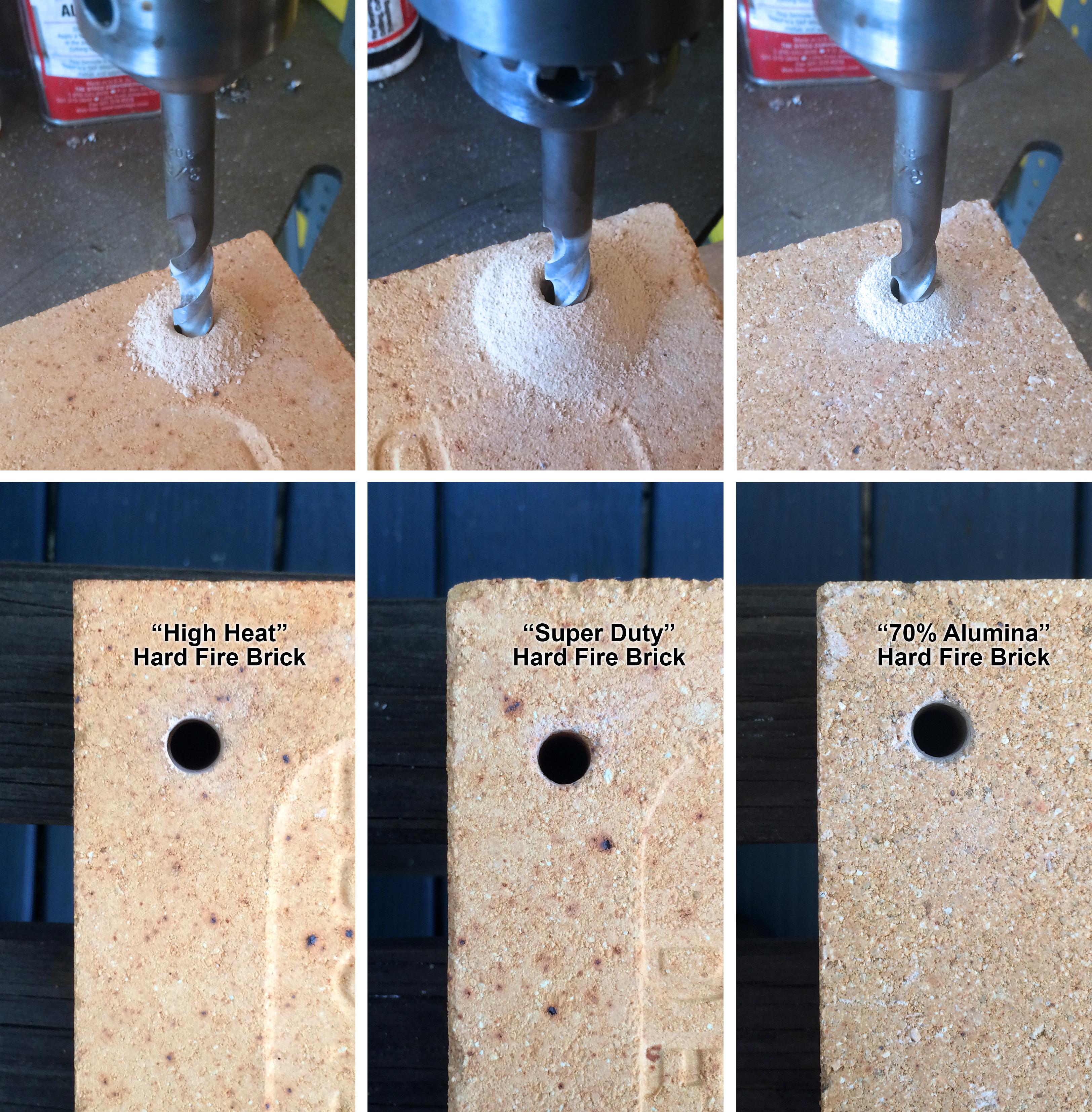
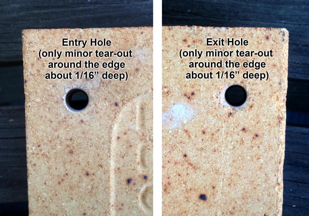
Frosty, those are the entry holes, but the exit holes really aren't too bad either. Here are both sides of the "high heat" brick: I'd say that all but about the first and last 1/16" of the holes are nice and round, straight, and with smooth sides. The 70% alumina brick had a bit more tear-out than the others and seems more granular in nature than the others. The masonry bits that I use have very "crisp" edges on the carbide inserts...almost what I would call "sharp." I can check on the brand, but I usually order them from McMaster-Carr. In any case, they seem to cut smoothly and evenly...at least that's my "physical"perception. At the microscopic level, they could very well be chattering away like mad, as you said. I've done a lot of stone foundation work and granite splitting with feathers and wedges, so I've drilled hundreds of holes in granite, schist, gneiss, and other stones with hammer drills, and some bits definitely hold up better than others, and some have deeper inserts than others, allowing more resharpening. I think that if one were to drill a hard fire brick with the brick tightly clamped against a piece of sacrificial hardwood, it might further reduce the tear-out at the exit edge. I'm guessing that a small amount of tear-out would be acceptable, as you might want to put a very small radius on the edge to help stabilize the edge and smooth the gas/air flow into the hole a bit. Al (Steamboat)
-
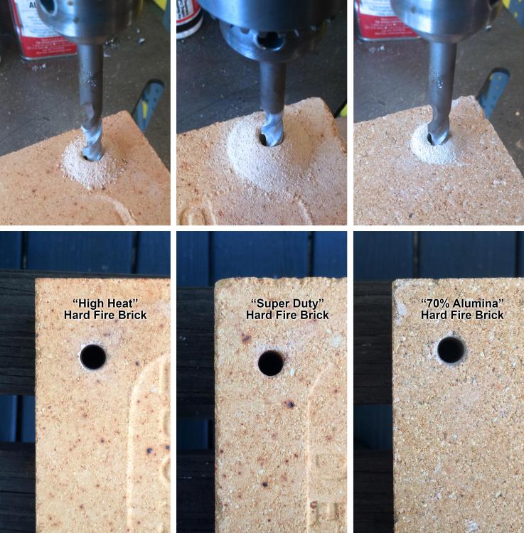
Ted, what specific kinds of hard fire bricks were you trying to drill? I've been able to drill hard fire bricks using an ordinary carbide-tipped masonry bit in a drill press (i.e., WITHOUT a hammer drill) quite easily. For example, as shown in the image below, I drilled holes through three different kinds of hard fire bricks with the same carbide-tipped masonry bit in a drill press, and I had no problem at all. I got these fire bricks from Sheffield Pottery in Massachusetts, and the terms in quotes are the nomenclature that they used on their website. The bit drilled through the first two types VERY easily, taking less than a minute to drill a 3/8" by 2.5" hole all the way through each brick (these are full-size bricks). I think that the "high heat" brick was a touch softer than the "super duty" brick, but both drilled quite easily. The third (70% alumina) brick was harder than the other two, and it took an extra minute or so to drill the hole through that one. All of these holes are quite smooth inside. After drilling the 70% alumina brick I noticed some erosion on the leading edge of the carbide tips, but I think I could probably drill three or four holes through the 70% alumina brick before having to touch up the bits on a wheel or use a new bit. However, I'm sure that I could drill a lot more holes in the first two brick types without replacing or sharpening the bit. More information about these bricks should be available on the Sheffield Pottery website. By the way, Ted, I like reading your posts. Keep it up! Al (Steamboat)
-

Looking for an anvil mount in Portland, Oregon
Steamboat replied to Ott's topic in Stands for Anvils, Swage Blocks, etc
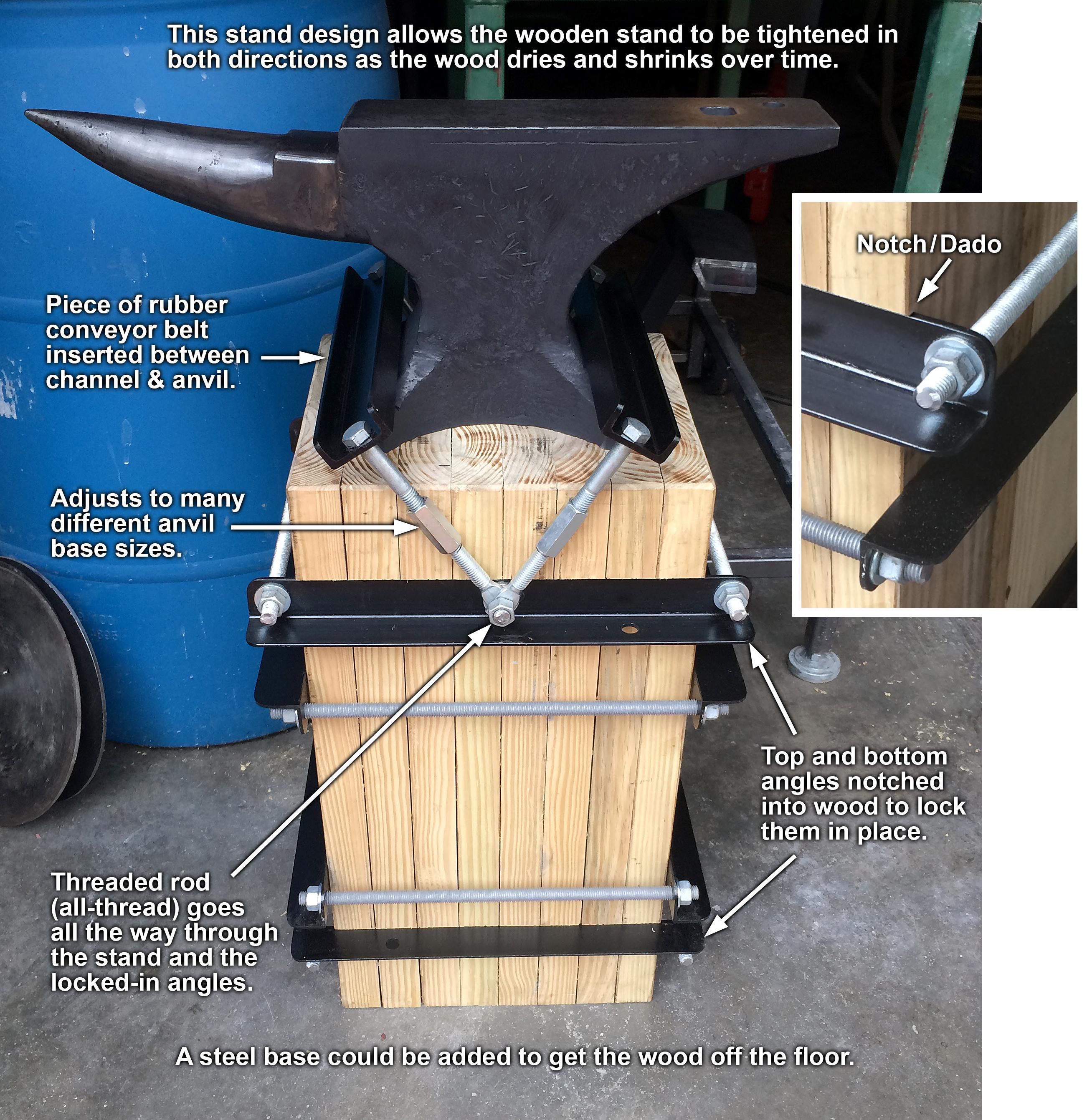
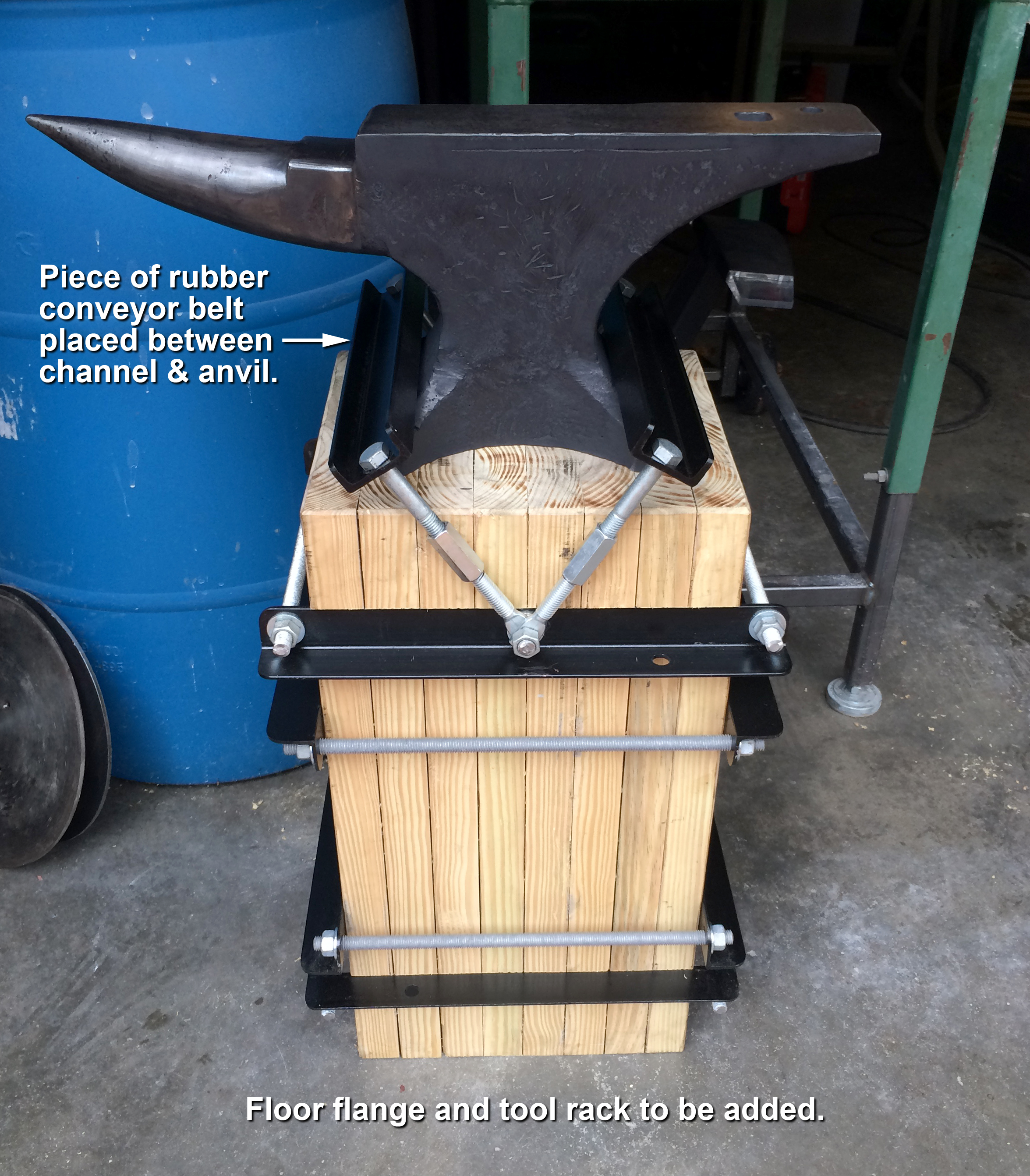
Here's an anvil stand that I built and posted on IFI a while back, but I thought it might be useful to post an updated image of it in this topic with more callouts added. This particular stand will work for small- to medium-size anvils. If I ever get a large anvil, I'd make a larger version of this stand. Al (Steamboat)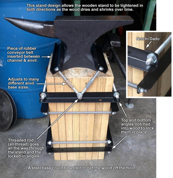
-
I've used Baldor motors for various projects, They should have product information packets for their motors on their website. Go to www.baldor.com and enter your motor's model number in the search field. In the results, click on "Products." The motor's product page should come up. There should be a link on that page to the product information packet. Hope that helps a bit. Al (Steamboat)
-
Old/New, Compact, "Convertible" Solid-Fuel Forge (photo heavy)
Steamboat replied to Steamboat's topic in Solid Fuel Forges
Thanks for the positive feedback. My wife said almost the same thing about not wanting to get it dirty, and that I should put it tn the living room instead (well, to be honest she quickly corrected herself and suggested putting it in my office instead of the living room). She's actually looking forward to using it herself. I think my gas forge makes her a bit nervous, and she took a short blacksmithing course where they used coal forges, so she should be more comfortable with this one. As to putting my projects into use, as long as I have a few photos of my projects in their "BD" state (before dirt), I don't mind getting them dirty. It helps to think of dirt as the "patina" of honest toil. Thanks, Dylan. -
Old/New, Compact, "Convertible" Solid-Fuel Forge (photo heavy)
Steamboat replied to Steamboat's topic in Solid Fuel Forges
Thomas, I think the video makes the blower look more powerful than it really is. I've found that it doesn't take a massive amount of pressure and volume to float an empty aluminum can. While it might be more blower than "necessary" for this forge, it works beautifully. Using the air gate, I can adjust the air flow from what you saw in the video down to where it will barely lift a Kleenex. The fan (or impeller if you prefer) is actually quite small, and there is a large empty space inside the housing beyond the outer perimeter of the fan blades. As it happens, I did carry out one "real" test of the blower. I wanted to see how much current it draws at different air gate settings. Here are the results: With the air gate completely closed (maximum restriction & minimum--virtually zero--flow), the motor drew 1.6 amps. As I gradually opened the air gate, the current draw increased to 1.8 amps by the time the air gate was completely open. This is with the ash dump door closed and the grate in place. When I removed the grate and opened the ash dump door, and with the air gate still completely open (minimum restriction & maximum flow), the current draw increased to 2.1 amps. So, the motor uses LESS current when the flow is more restricted and it's pumping less air through the blower. And the motor gets its cooling air from outside the blower housing anyway, so I think we're good with this blower. Like everything else, I'll check the motor temperature with an IR thermometer during a long forging session, but I think it should be fine. I'm hoping to use the forge again this weekend and post a few images of it in use. Al (Steamboat) -
Old/New, Compact, "Convertible" Solid-Fuel Forge (photo heavy)
Steamboat replied to Steamboat's topic in Solid Fuel Forges
Glad you liked it, Frosty! I really try to pay attention to the details on everything that I build, which drives my wife crazy sometimes, since home-related projects sometimes (read "almost always") take longer than usual to complete. As to a rheostat, there's no speed control; I just use the air gate, which works fine. So far, in some short fire-up sessions, the hardware under the hearth does not seem to be getting too hot. I'll check it again after a longer session, but I suspect that it should be OK. If not, I'll post it here. As mentioned, I know that the ITC-100 was unnecessary and probably insignificant as far as any positive effects in the duck's nest, but there it was, a neglected, half-used jar of the magical slurry, just sitting by itself on a shelf, staring me in the face and silently pleading to be used instead of left to gather dust. I couldn't help myself...I didn't have the heart not to use it. If nothing else, it made the castings look pretty until I got them dirty. Al (Steamboat) -
Old/New, Compact, "Convertible" Solid-Fuel Forge (photo heavy)
Steamboat replied to Steamboat's topic in Solid Fuel Forges
Beer Can Forge Blower "Test" I made a short video the other day of my new solid-fuel forge. I was just curious as to how much pressure and volume the blower was putting out, and so I conducted a non-scientific and basically meaningless "test" (if you can call it that) using an empty beer can. It didn't really give me any data, other than demonstrating that the blower was pumping air in the right direction (which I already knew), but it was still kind of fun. blower-beer-can-test.mp4 Al (Steamboat) -
Old/New, Compact, "Convertible" Solid-Fuel Forge (photo heavy)
Steamboat replied to Steamboat's topic in Solid Fuel Forges
Thanks, Tom. It was rather fun to build...and I enjoy making modifications, too. Al (Steamboat) -
Old/New, Compact, "Convertible" Solid-Fuel Forge (photo heavy)
Steamboat replied to Steamboat's topic in Solid Fuel Forges
Very good observation, JHCC, and I had the same thought, which is why I designed it so that the grate can be easily lifted off, allowing either the large or small duck's nest to be used with or without the grate in place. That reminds me of one little tweak I'd like to make: For using the larger duck's nest with the grate in place, I'd like to make a ring to go around the flange of the grate so that the bottom of the duck's nest will be flat in that configuration. That should be an easy mod. It could just be a couple of large washers, or I could cut a couple of rings with my plasma cutter. I could also fabricate a flat grate, which would give me an even deeper duck's nest when using a fuel that doesn't need a clinker breaker. With the current raised grate, there is enough clearance over the clinker breaker that the breaker won't strike the grate. However, if I made a flat grate, the clinker breaker would strike it IF the clinker breaker is rotated. However, that might be useful, since "rattling" the grate with the clinker breaker might dislodge small clinkers or debris in the grate. I plan to pick up some coke and charcoal soon to see how those fuels work with the forge. As to the horrible precedent, (insert fiendish laugh here). Cheers, Al (Steamboat) -
Old/New, Compact, "Convertible" Solid-Fuel Forge (photo heavy)
Steamboat replied to Steamboat's topic in Solid Fuel Forges
Thanks to both of you. I'm sure that fire clay would have worked just fine. One "possible" positive note about the castable refractory is that I've trundled the forge numerous times over some pretty bumpy and hard surfaces, which has given it a good shaking up, especially with the cast-iron wheels, and so far, no cracking in the refractory castings. Maybe fire clay would also hold up well to some bumping around...possibly depends on the type of clay and mixture, etc. If I didn't already have some nearly-expired castable lying around I would have gone with some kind of fire clay, which I can get from a local pottery supply house. I was thinking that inside the duck's nest an ITC-100 coating might reflect some heat back into the fire, but it's probably not a significant factor. I've still got some leftover ITC-100 for the gas forge. When that eventually runs out I might experiment with other coatings. Steamboat -
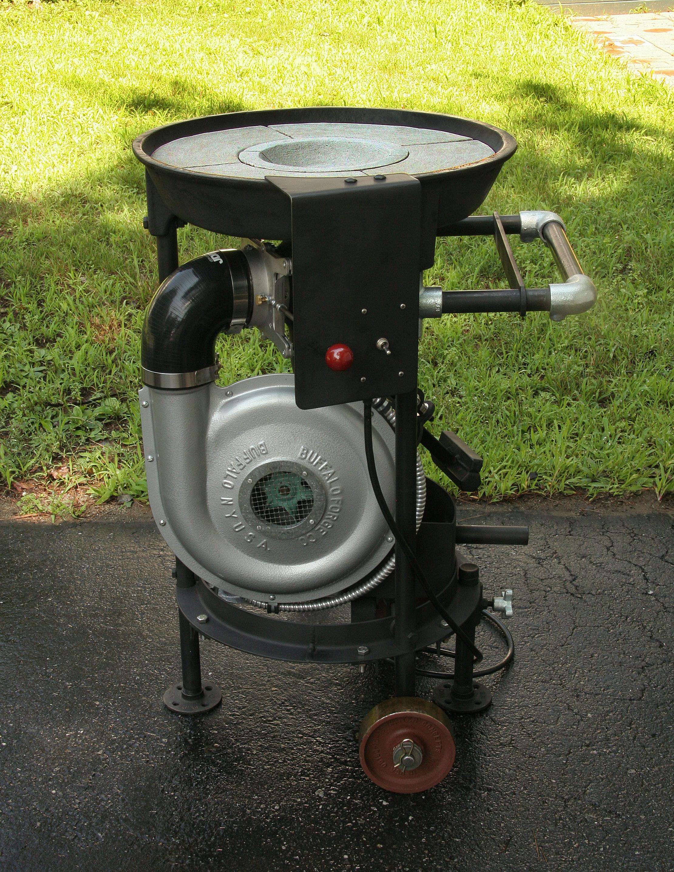
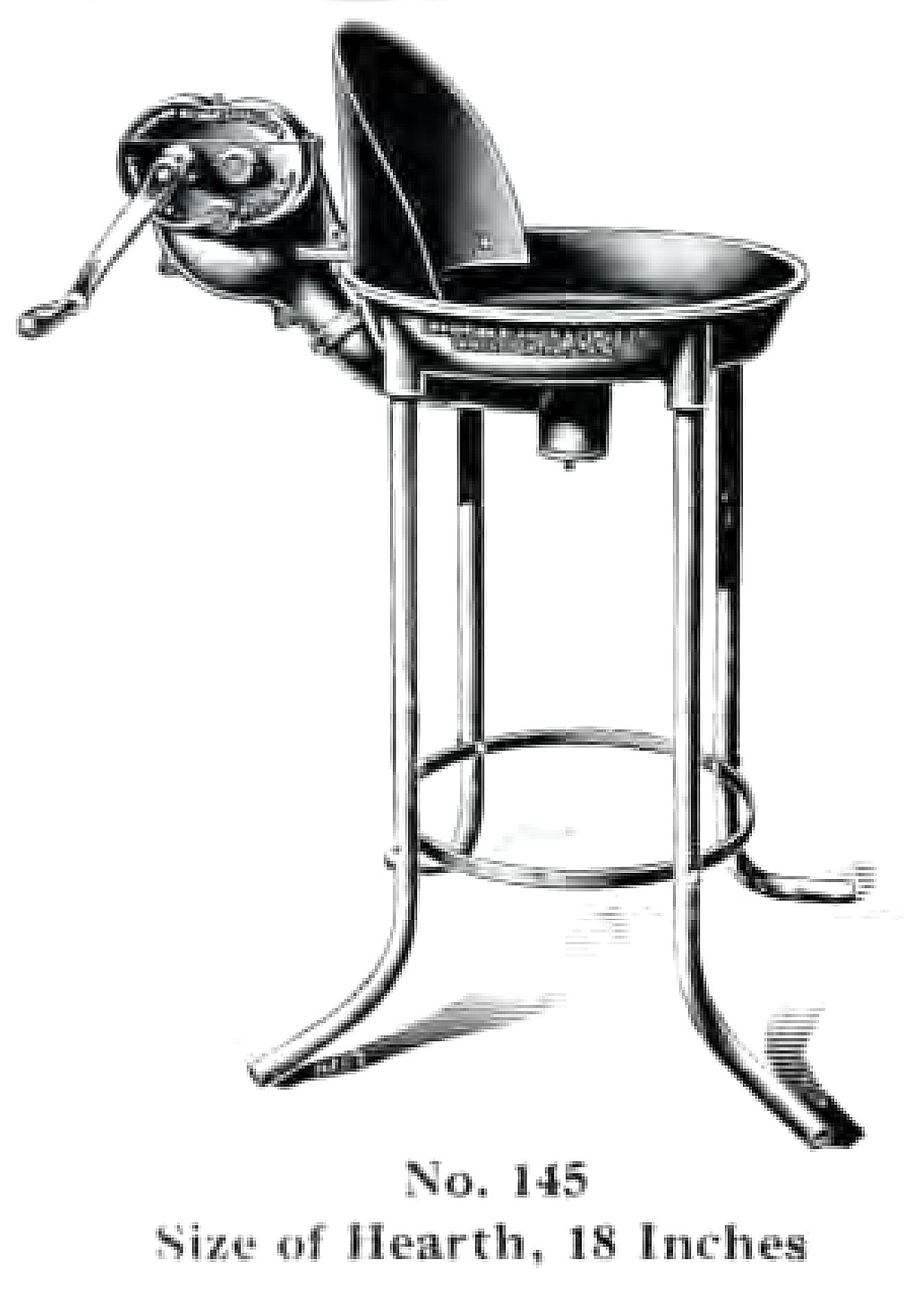
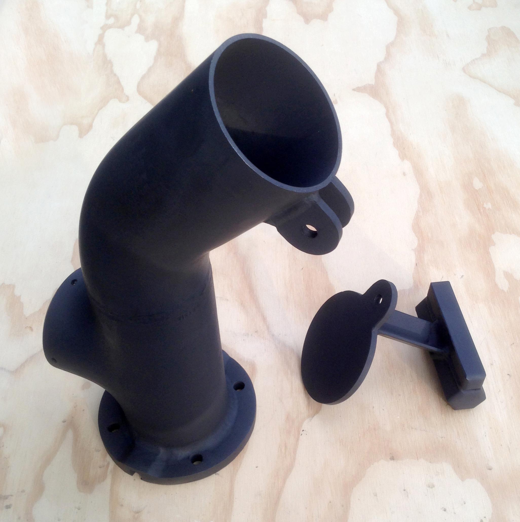
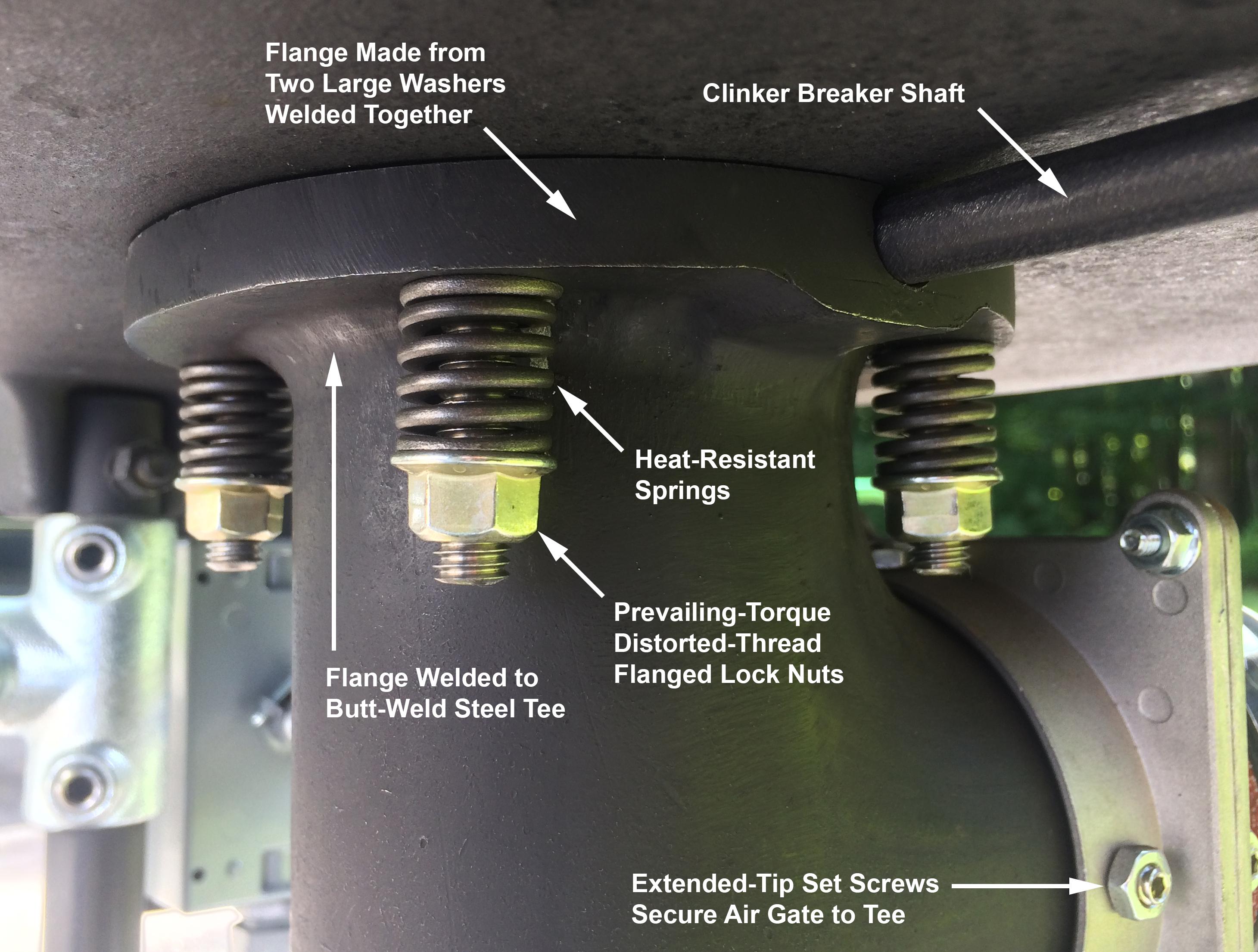
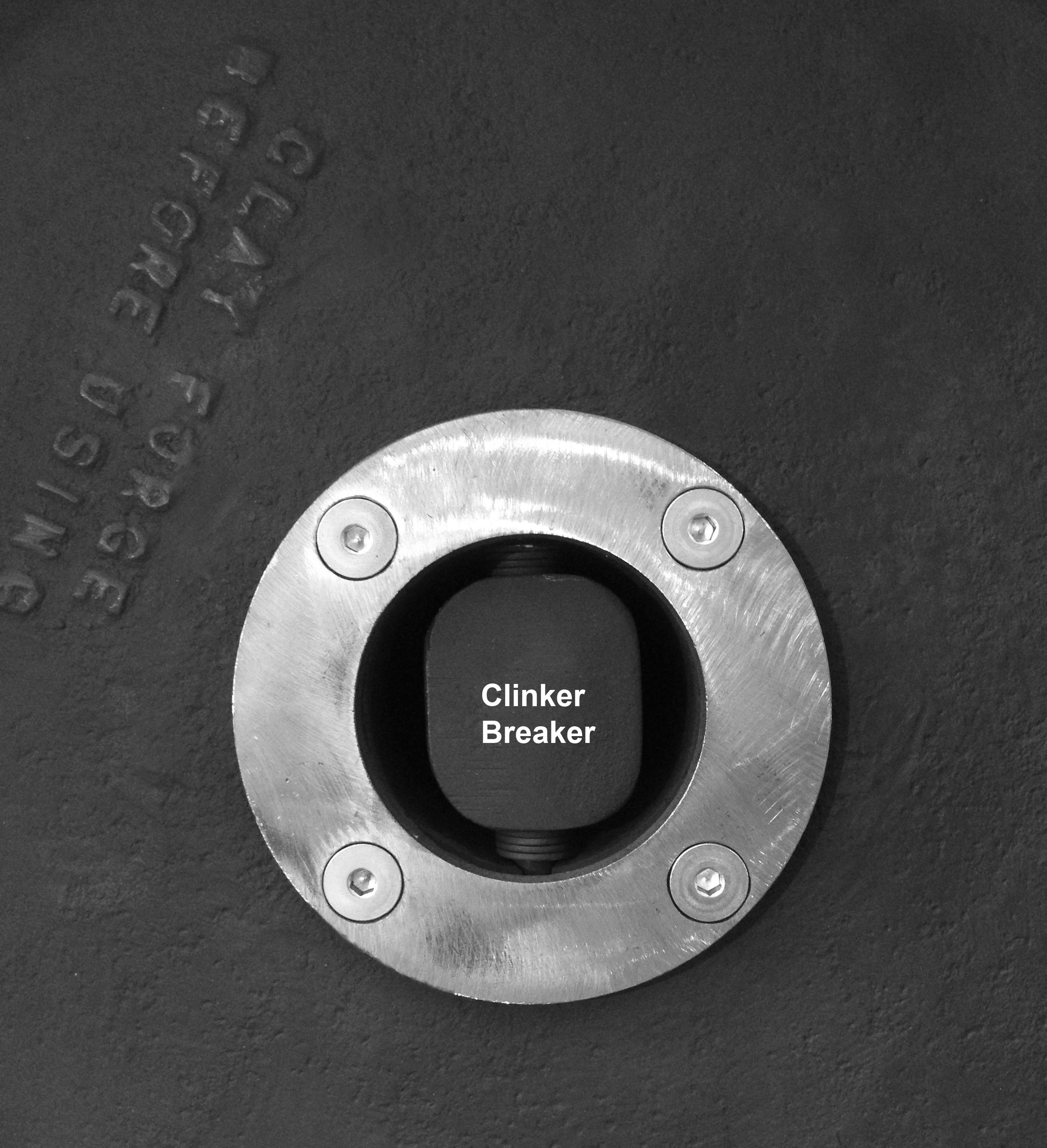
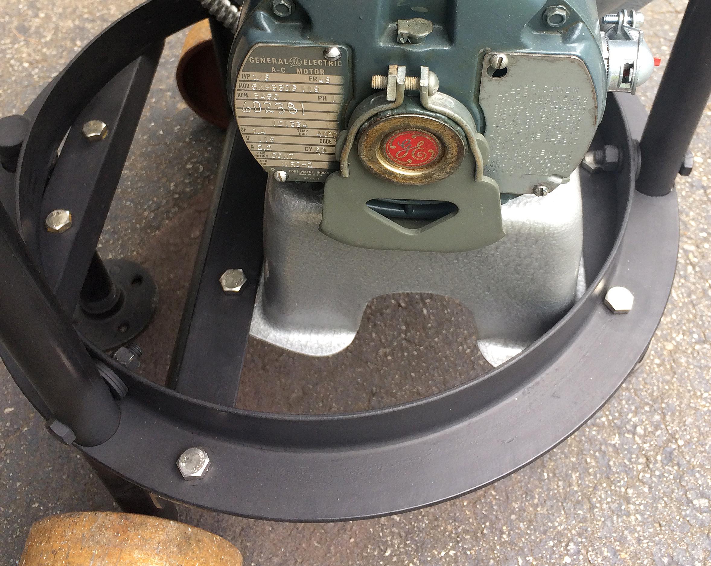
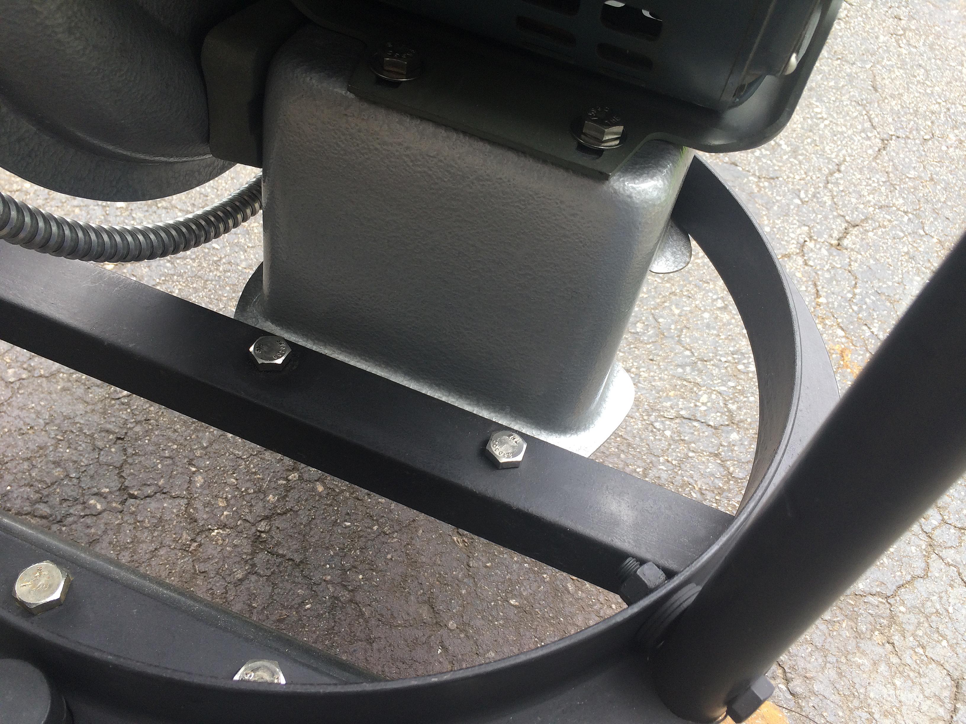
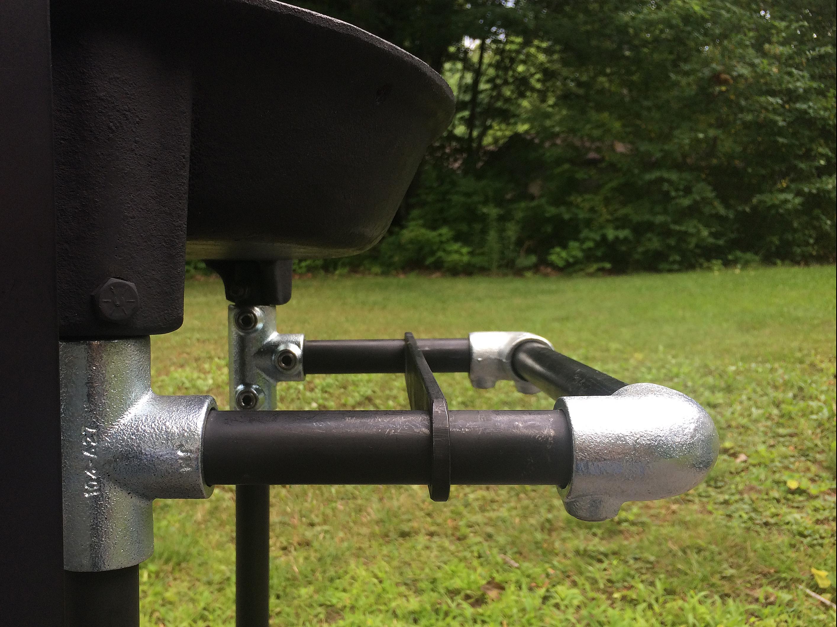
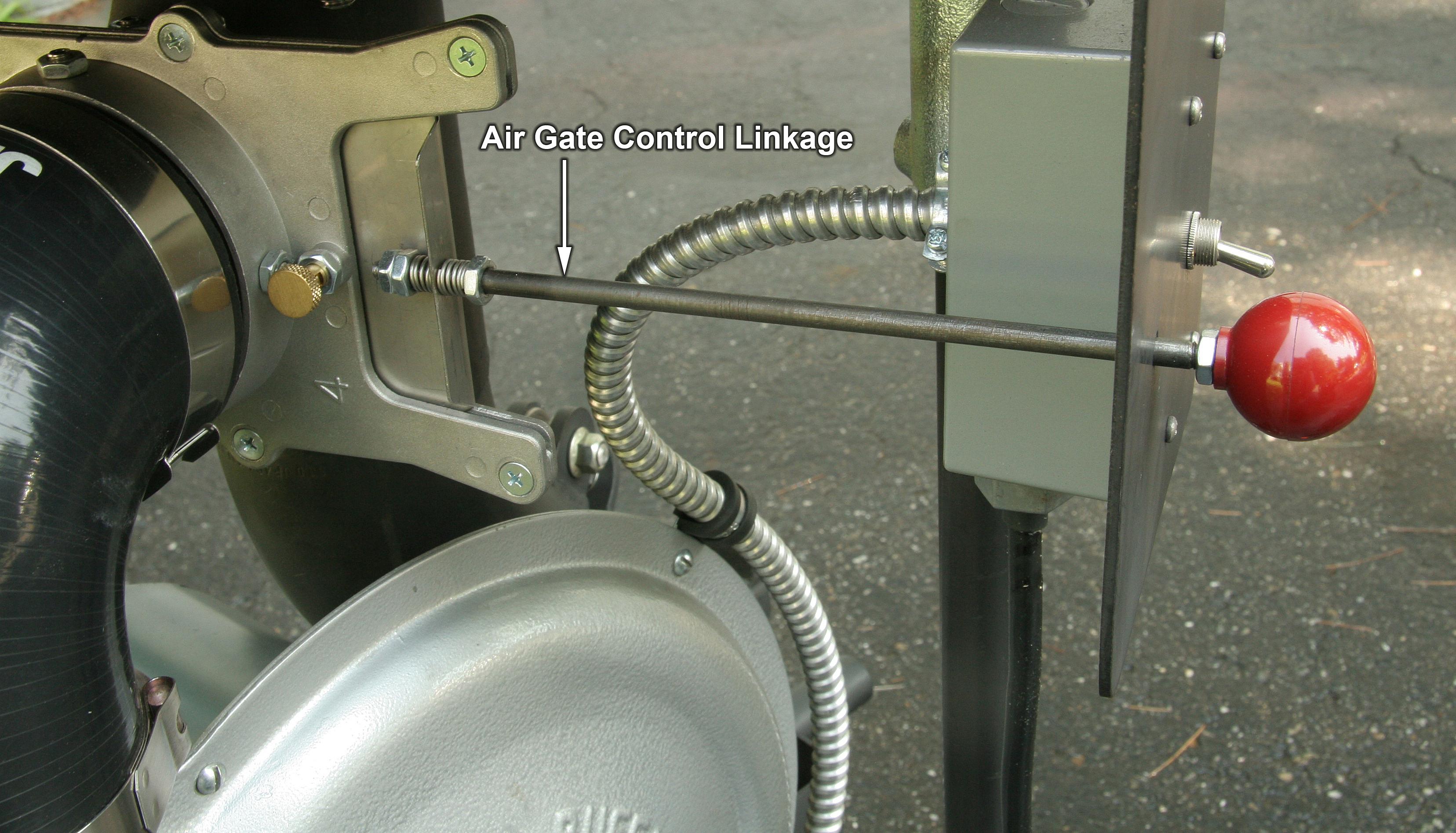
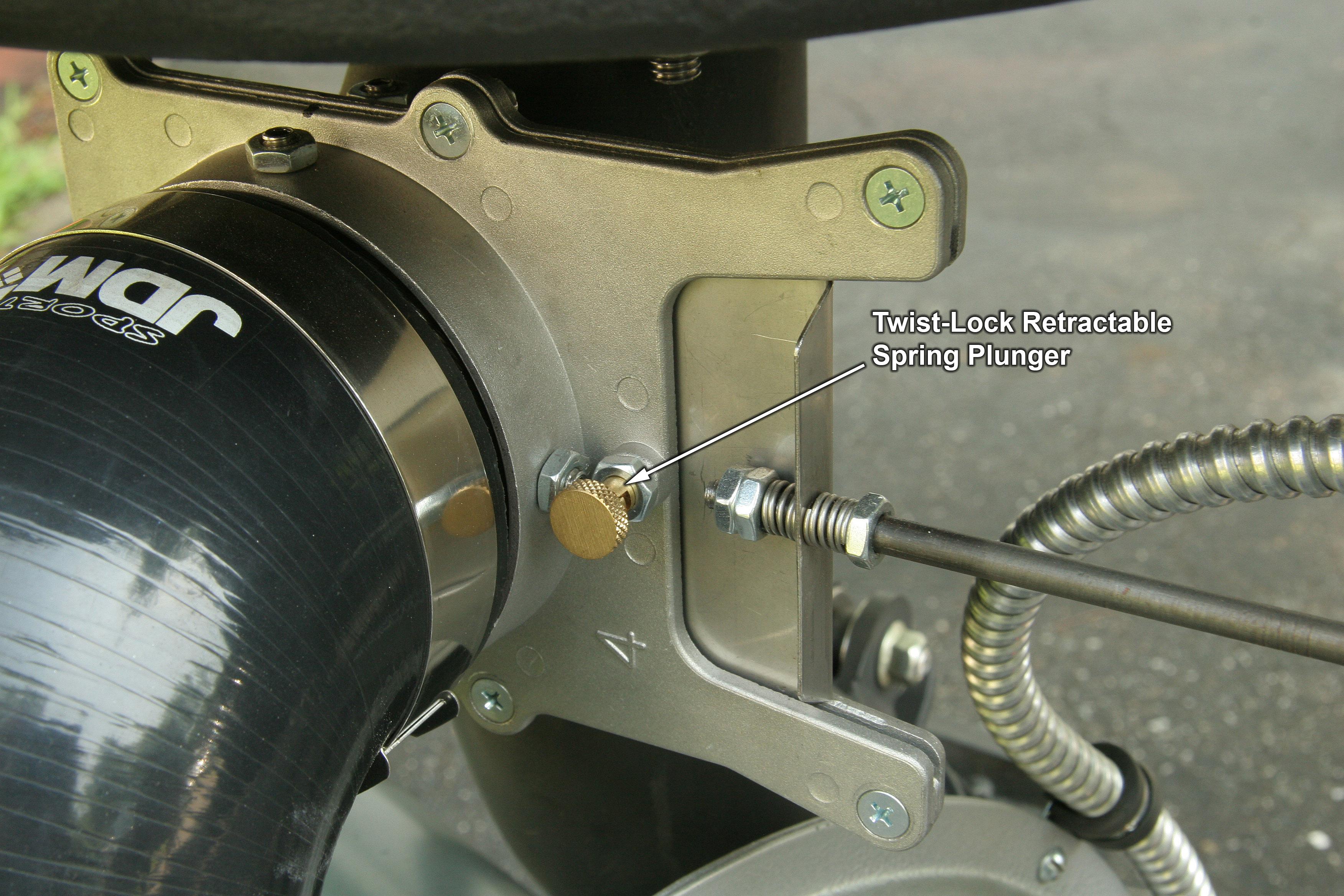
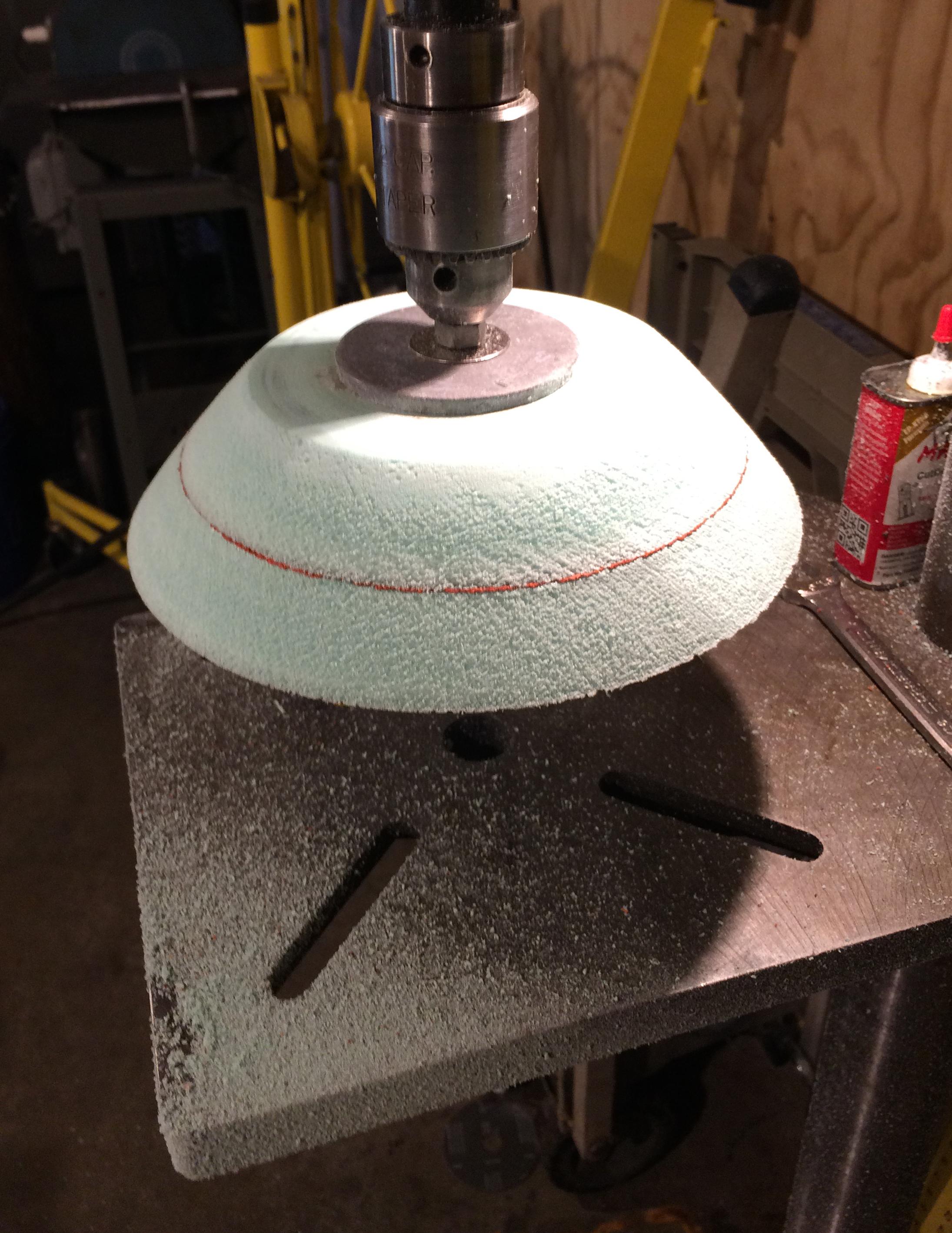
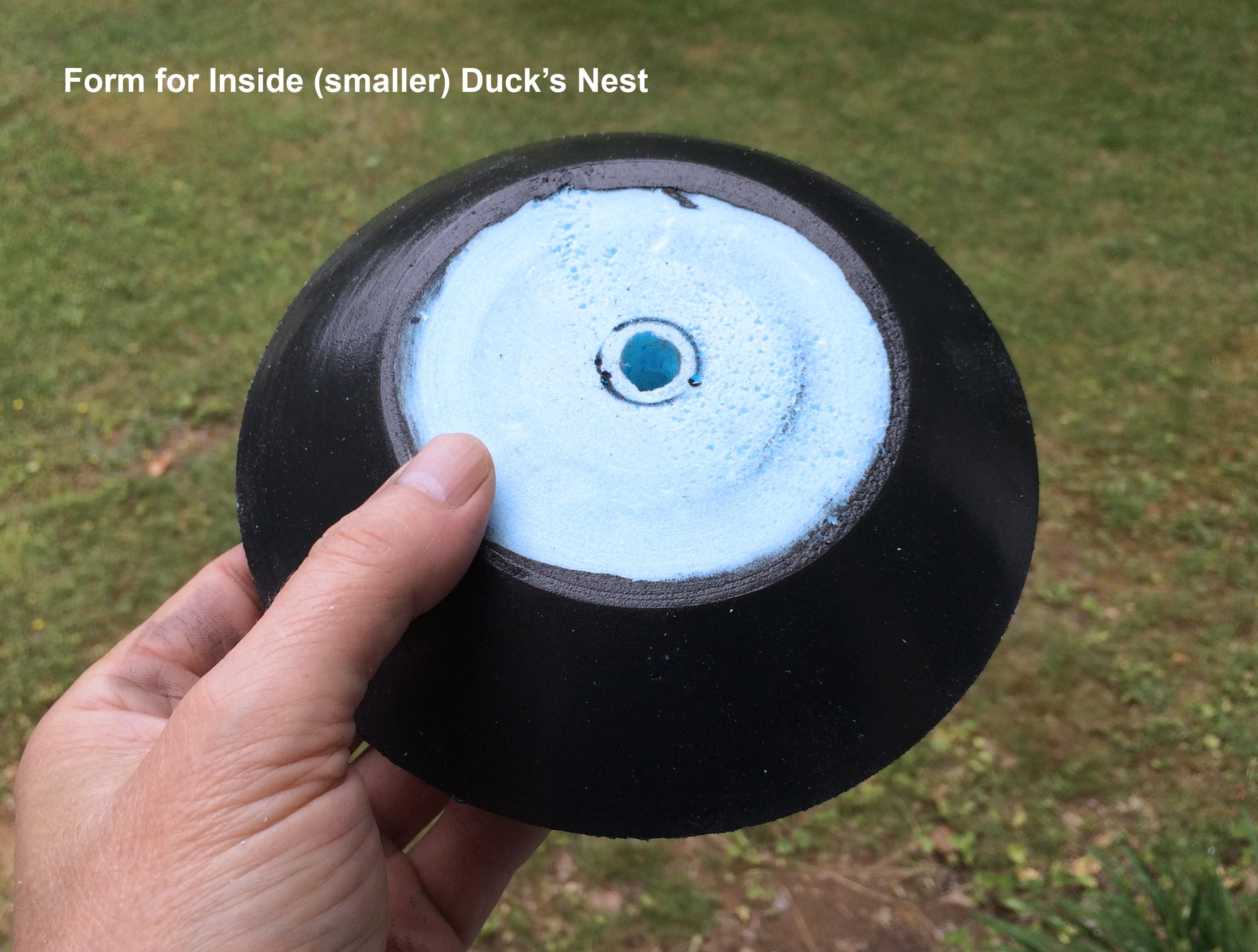
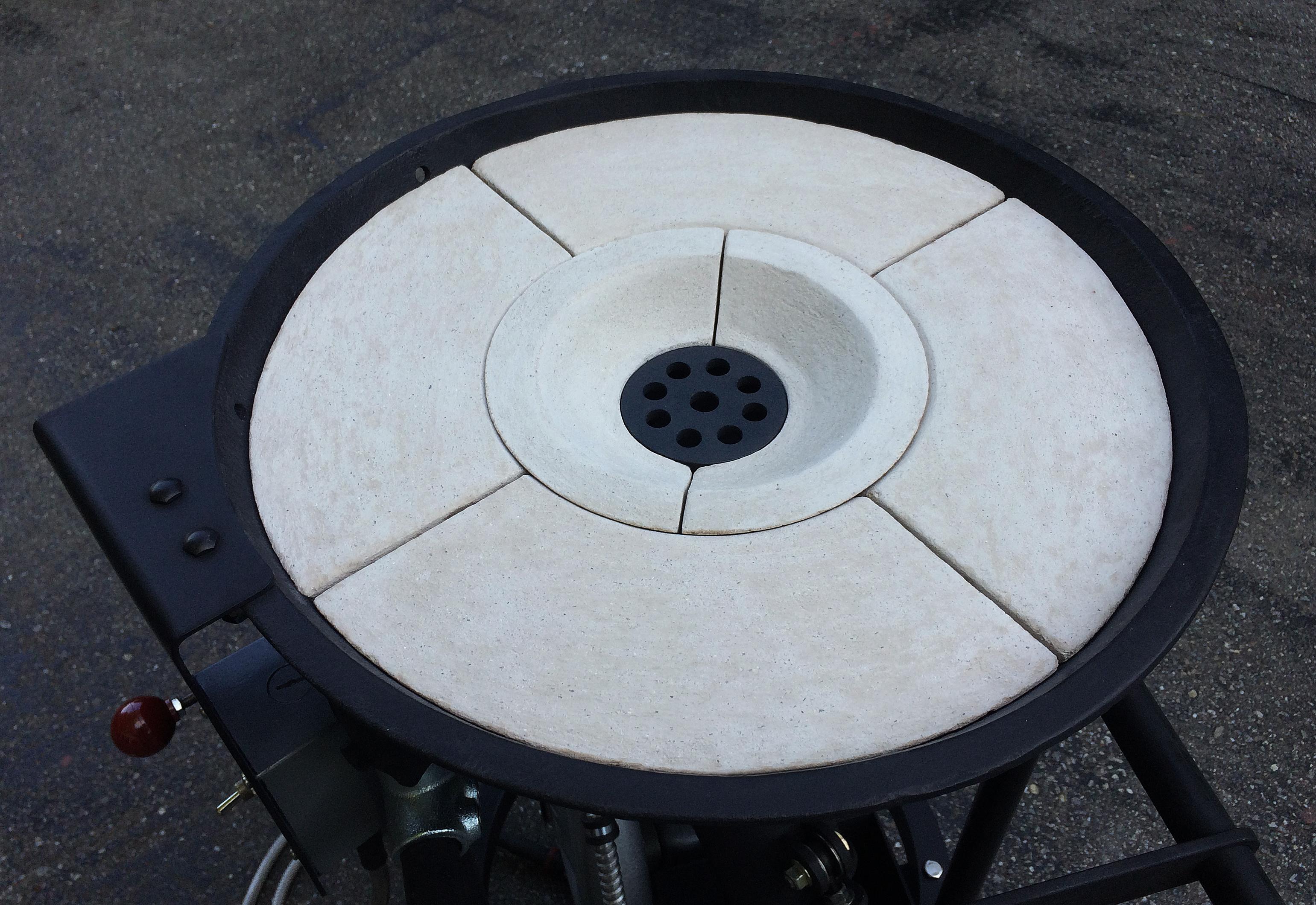
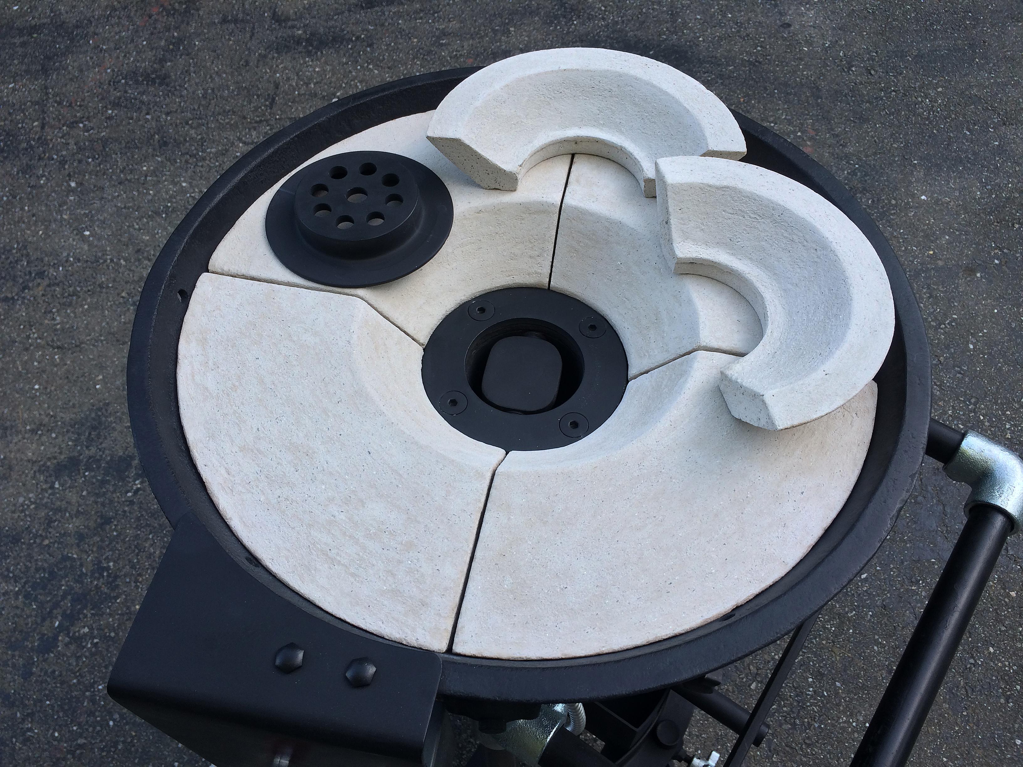
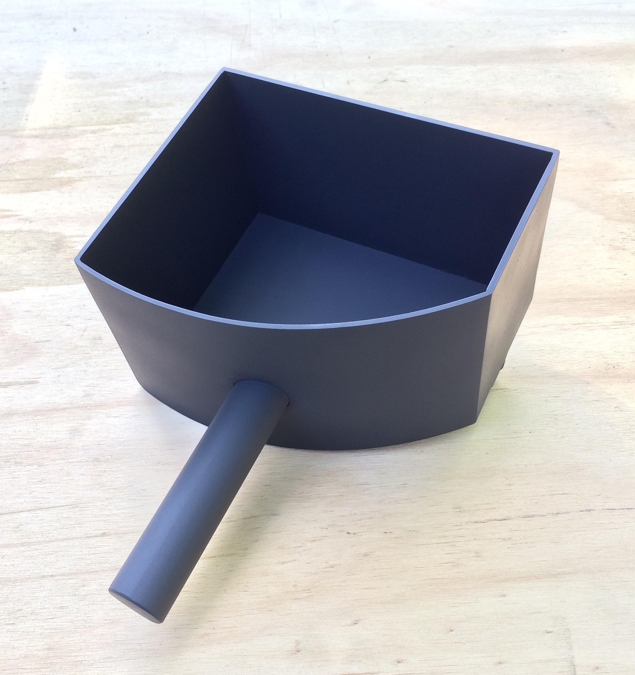
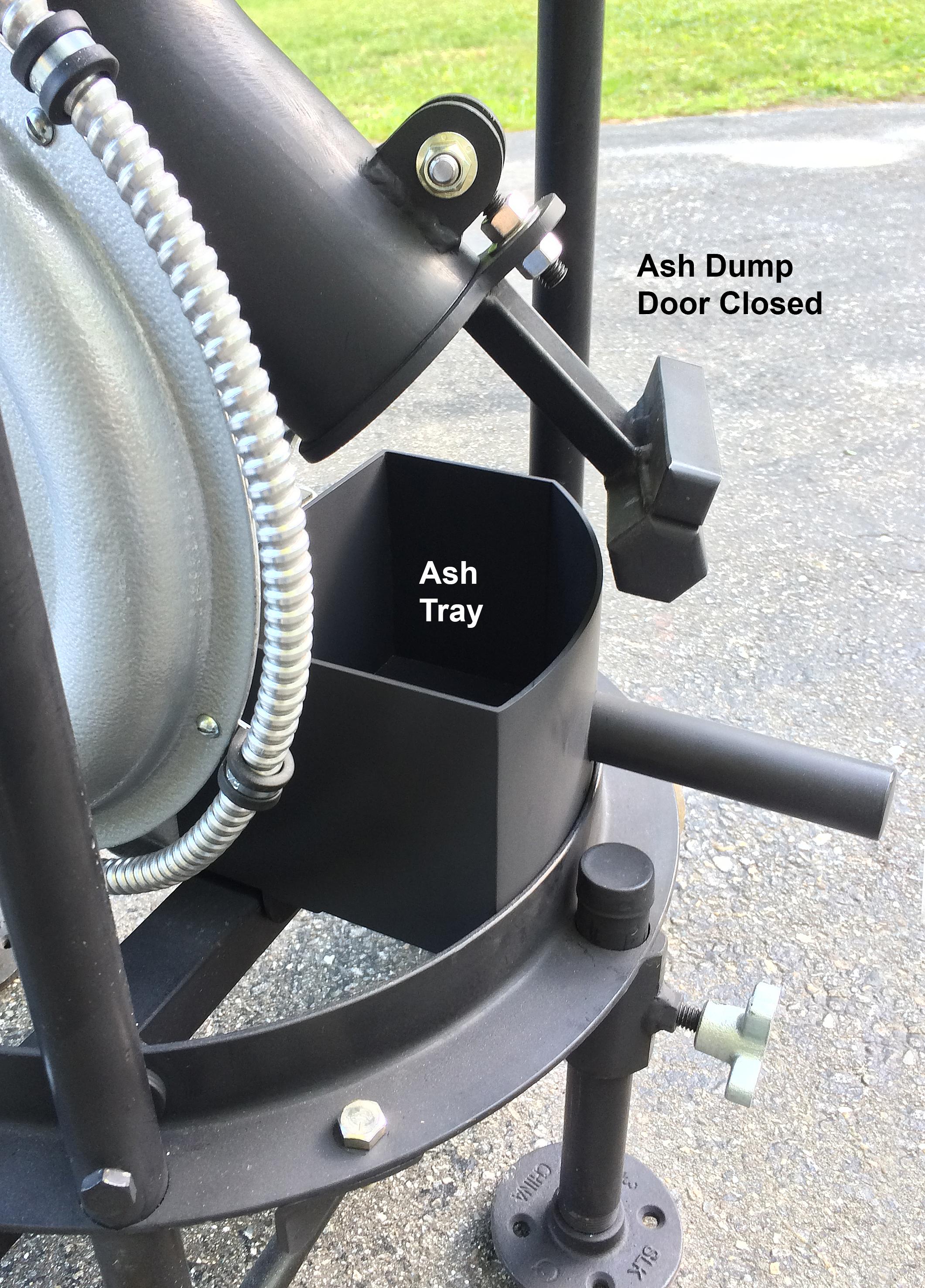
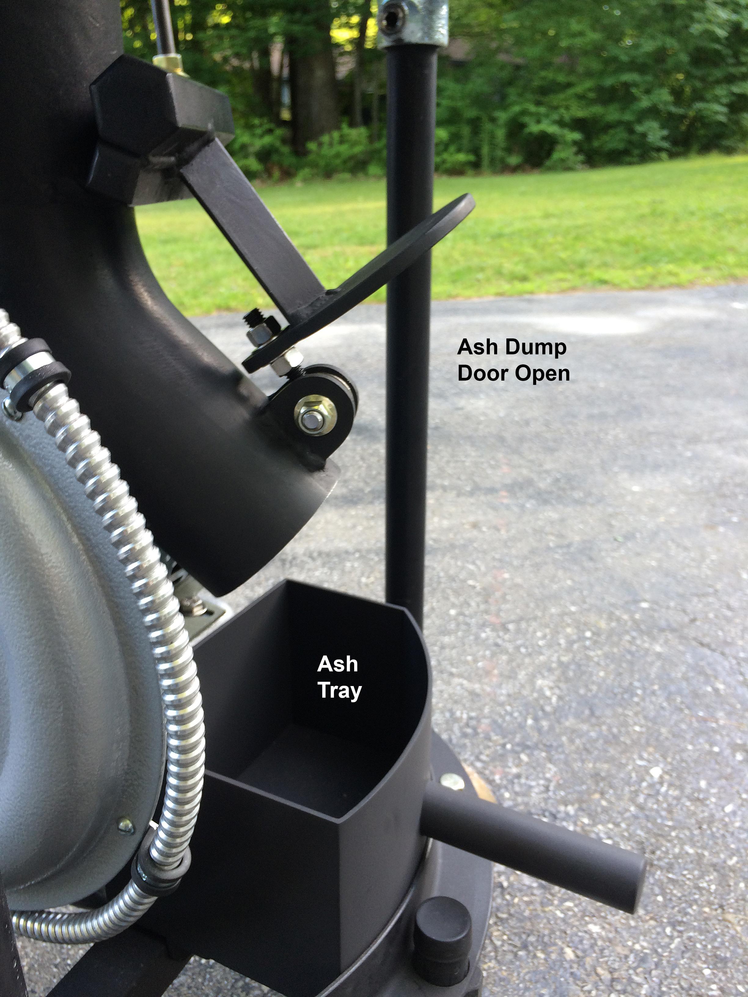
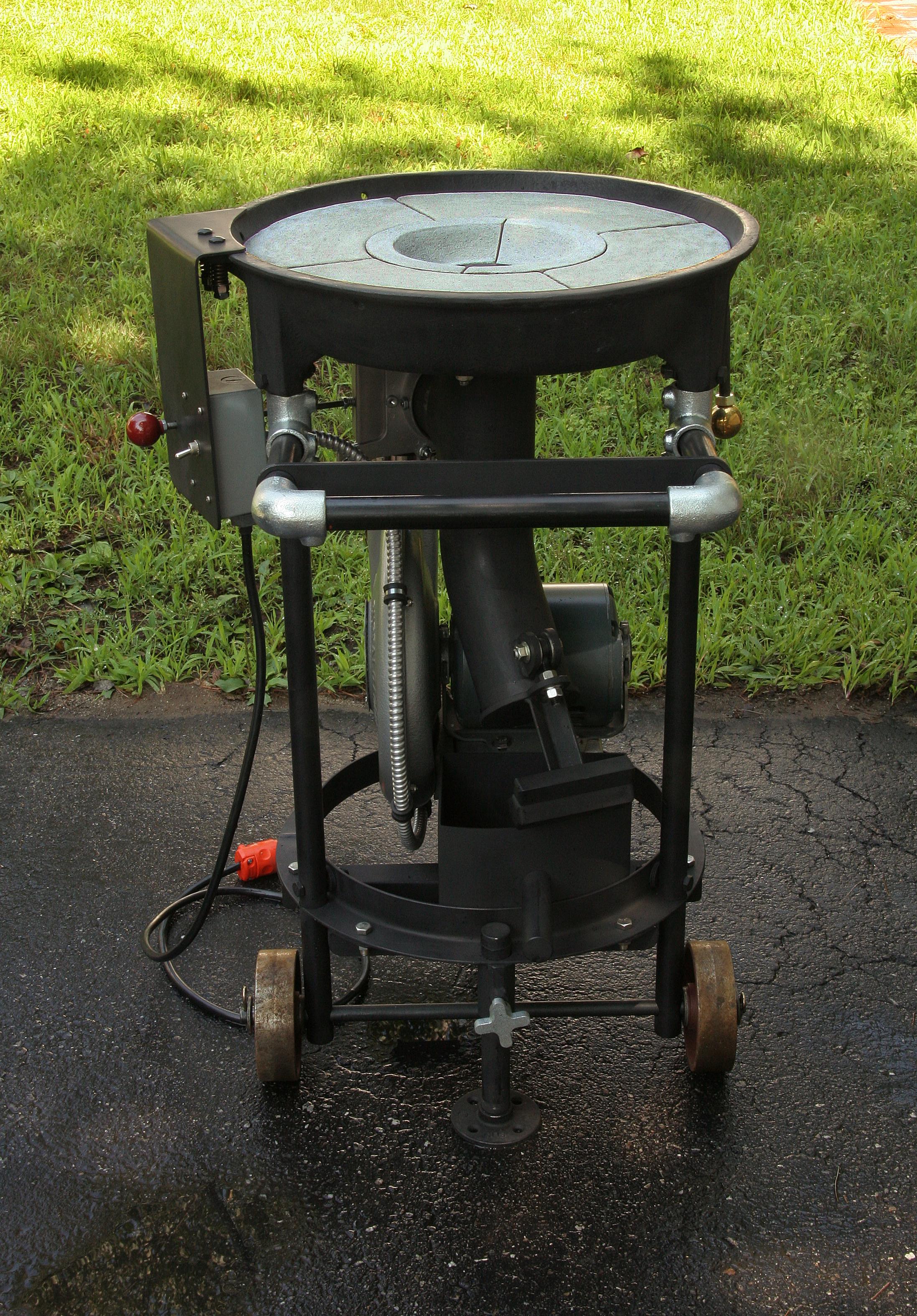
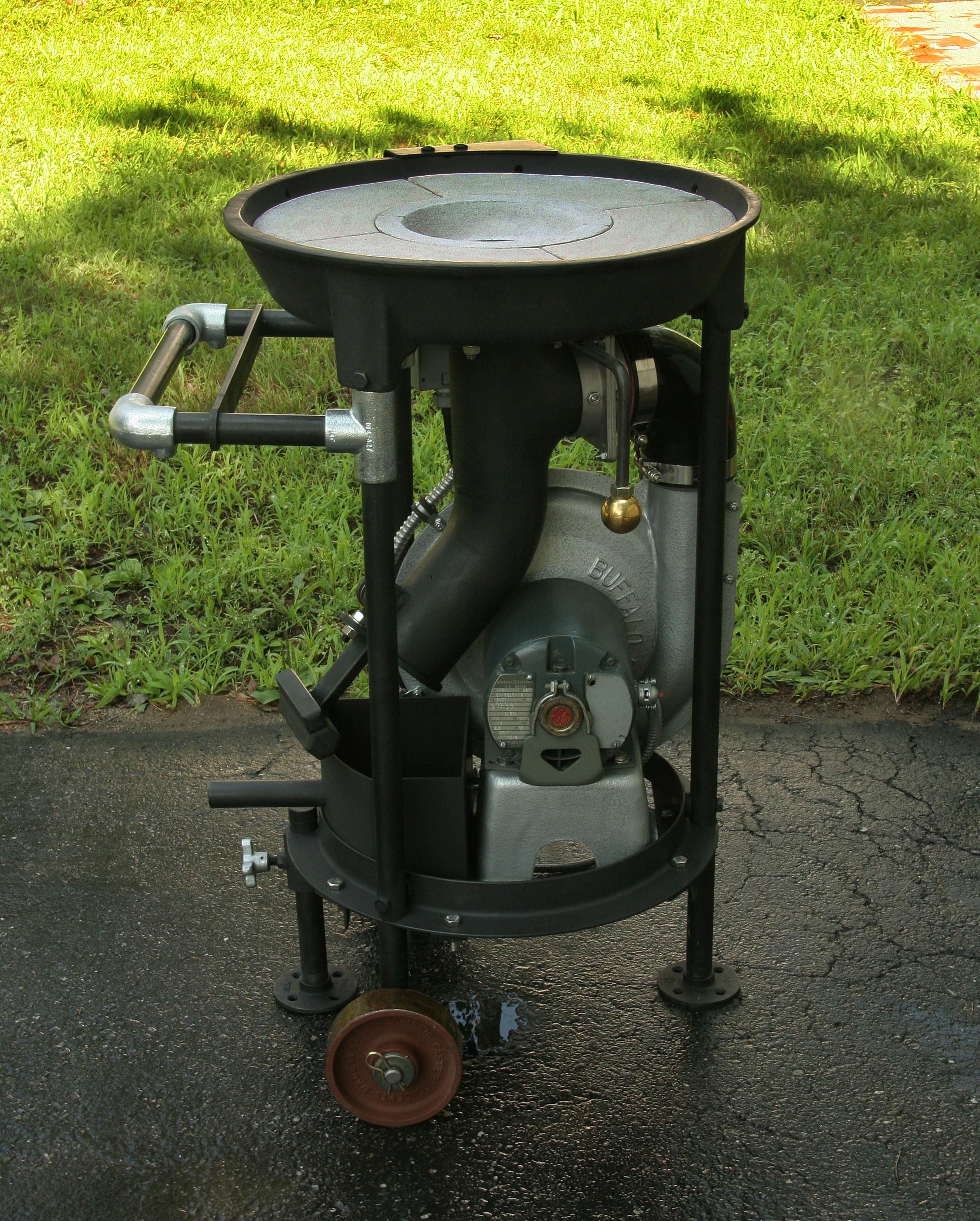
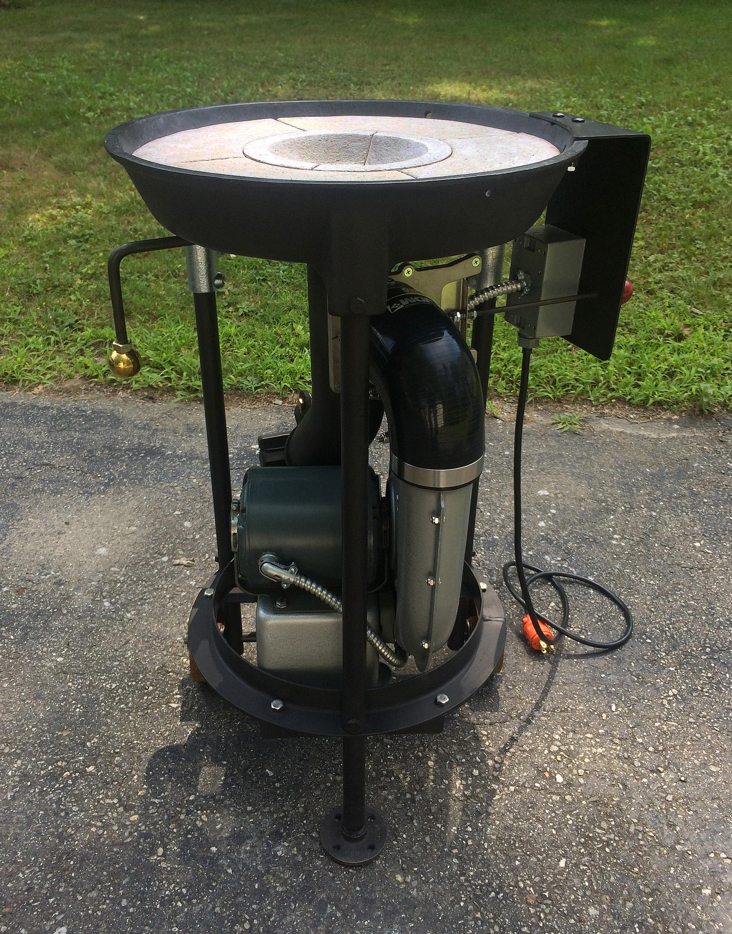
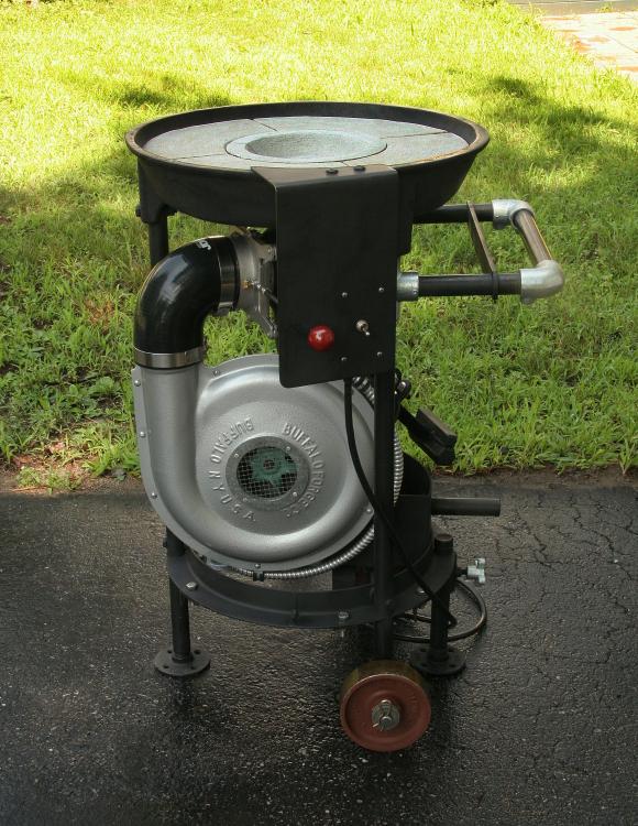
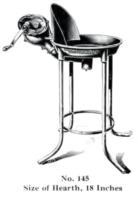
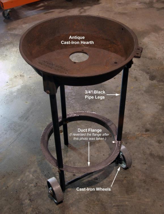
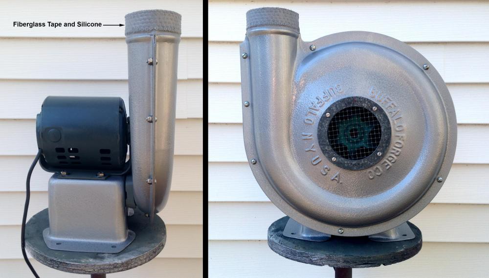
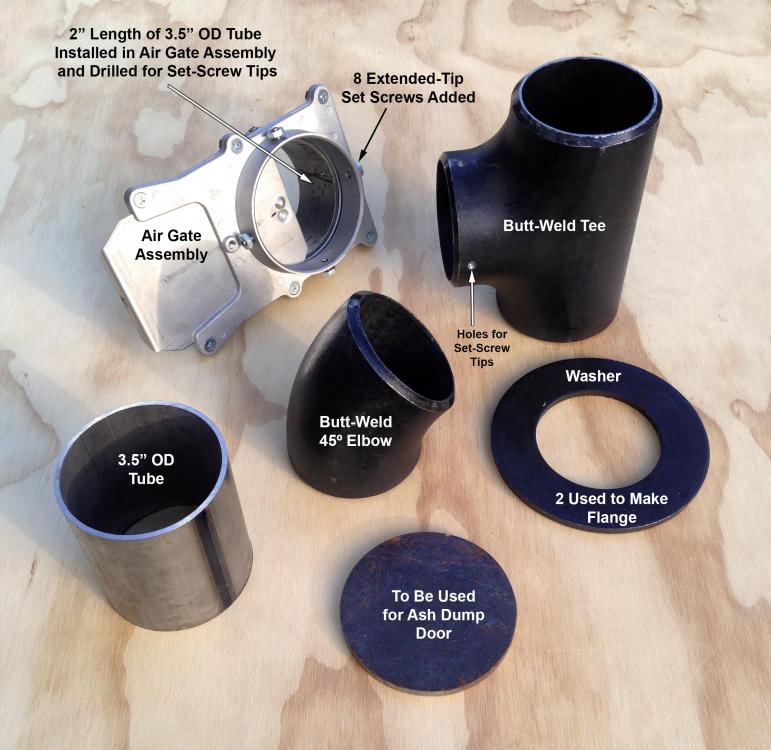
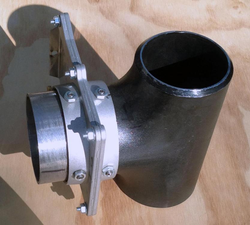
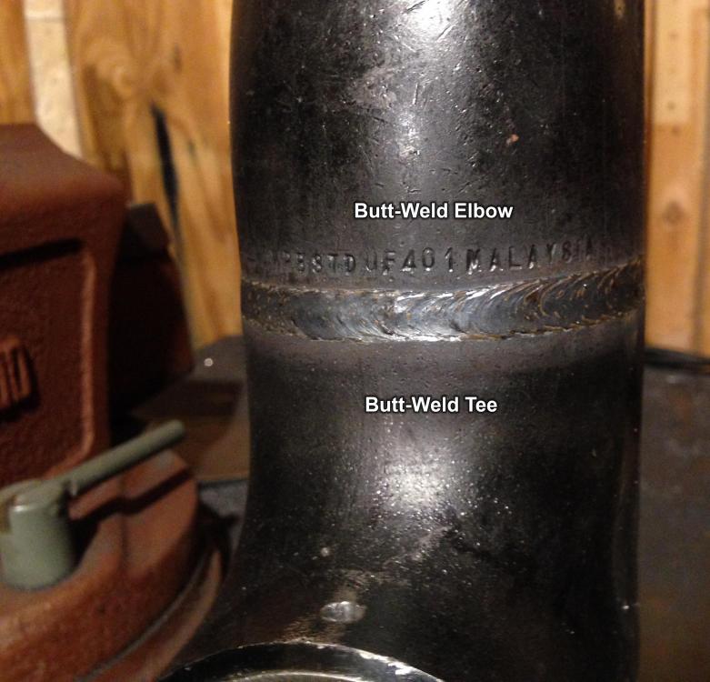
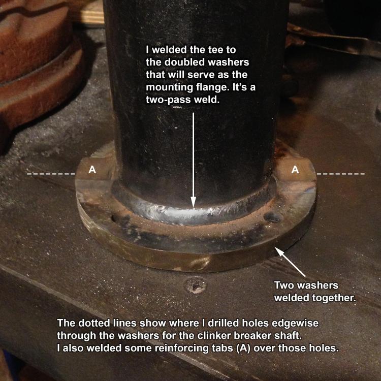
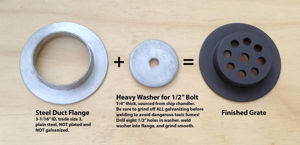
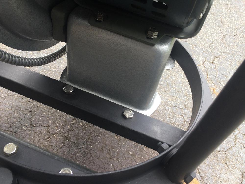
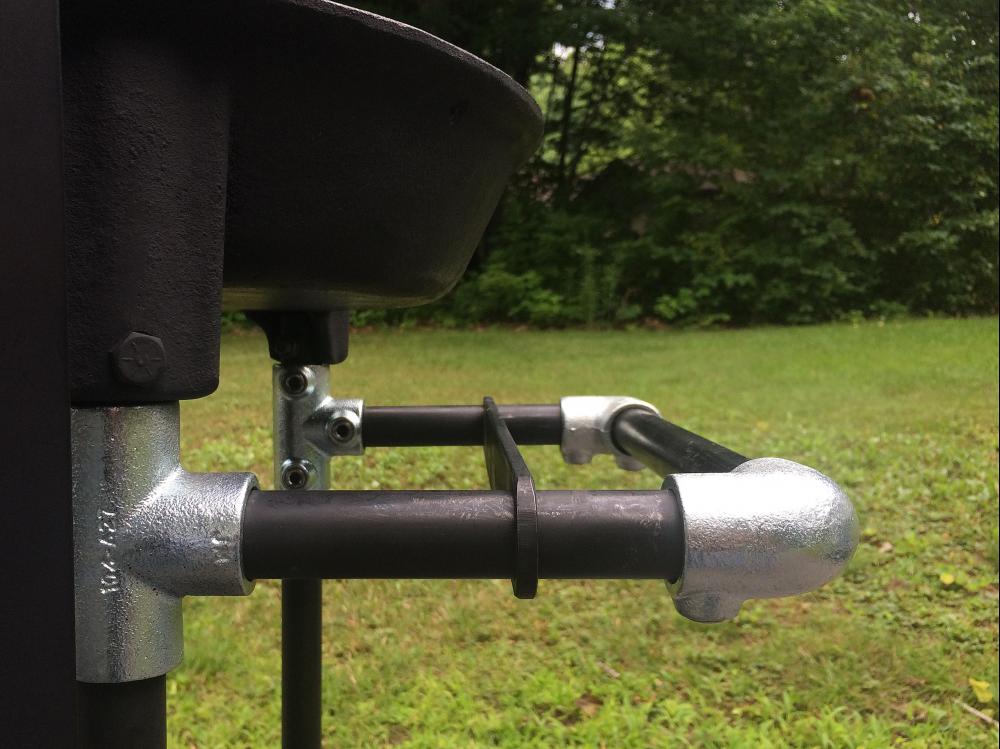
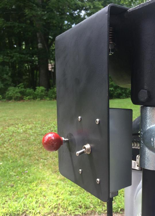
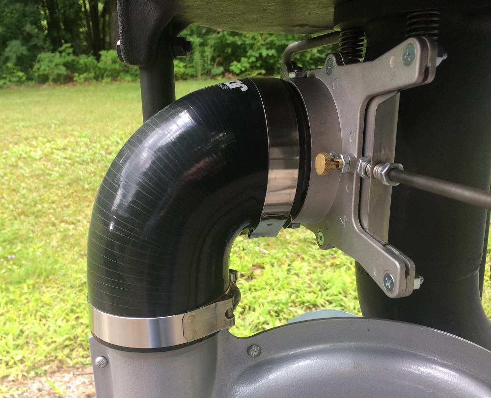
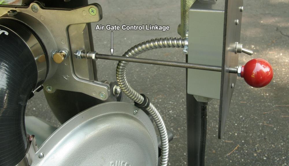
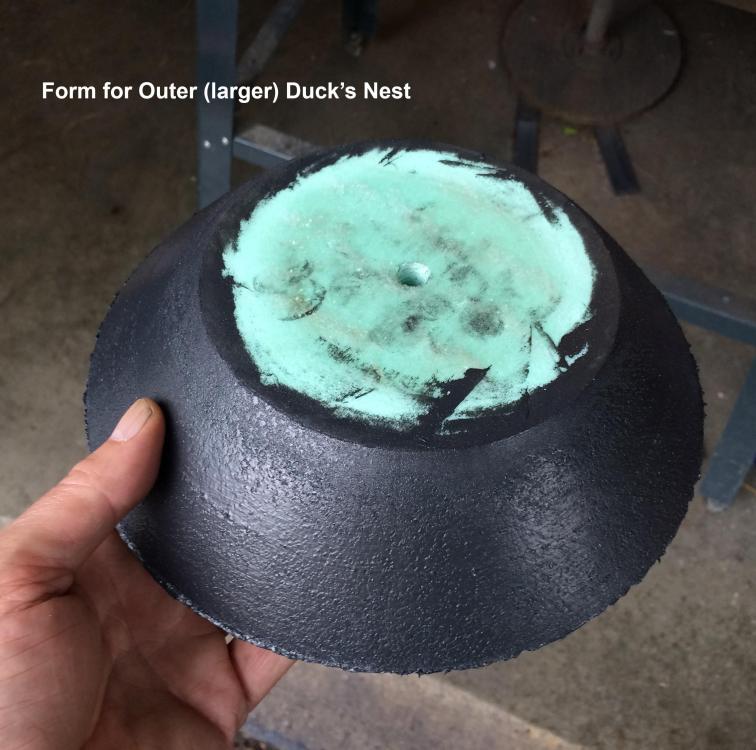
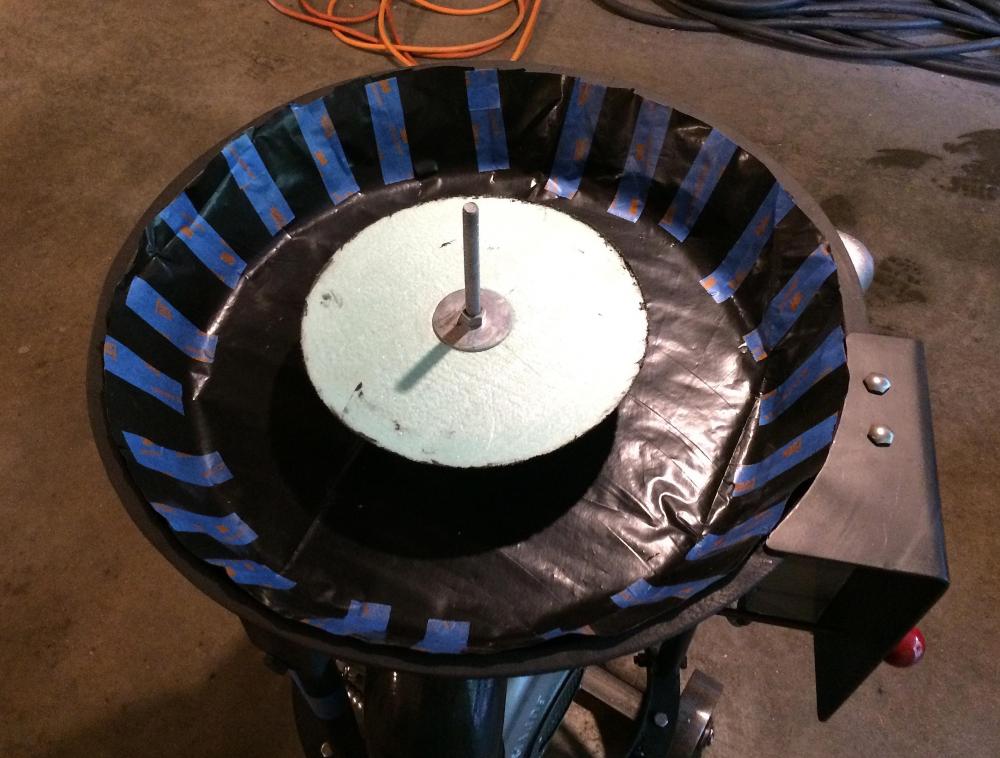
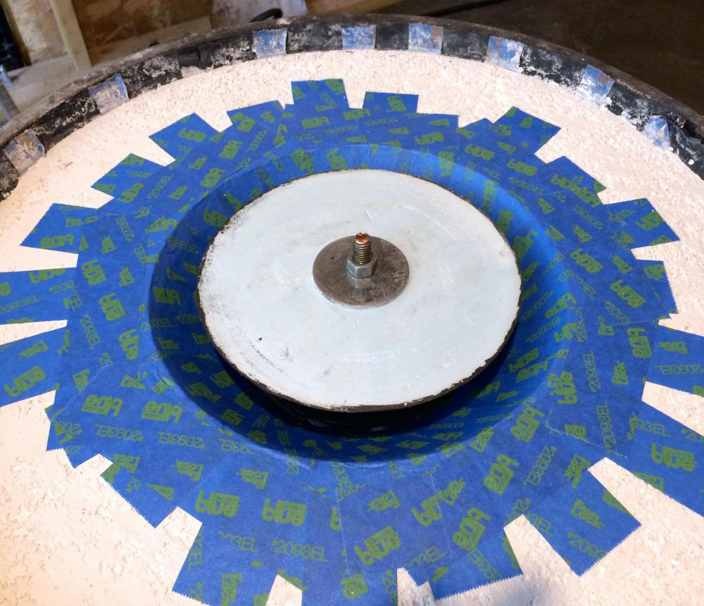
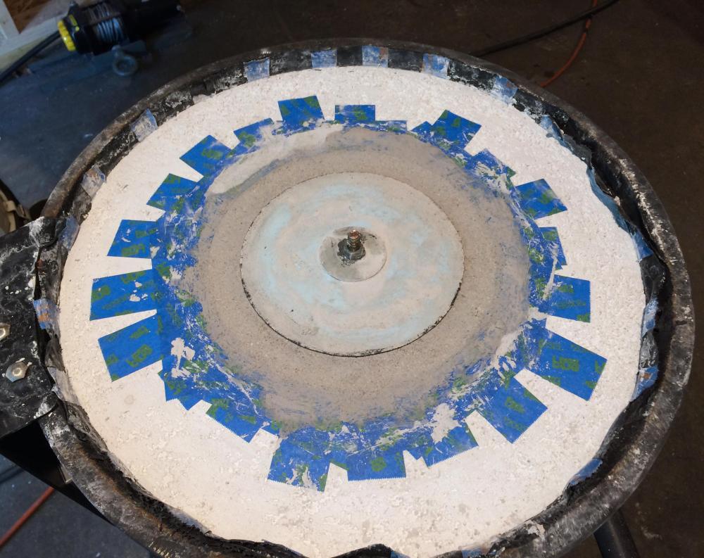
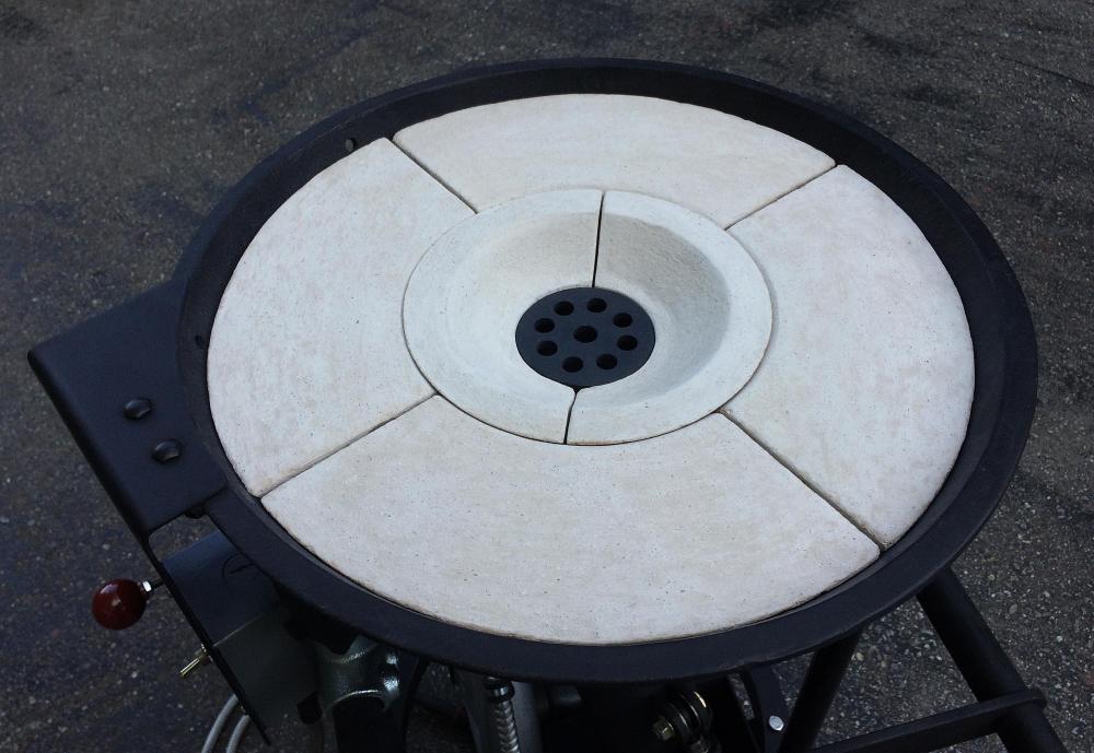
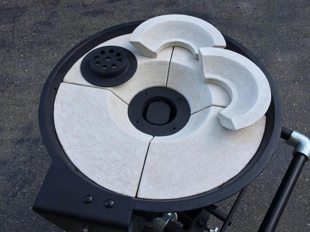
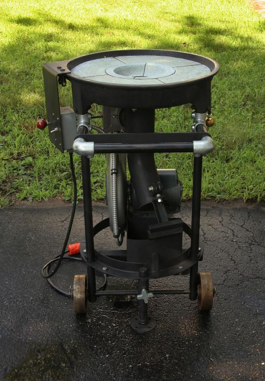
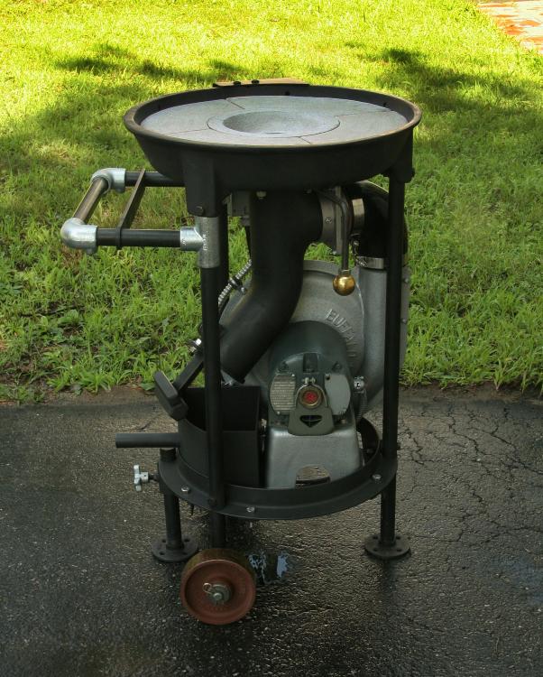
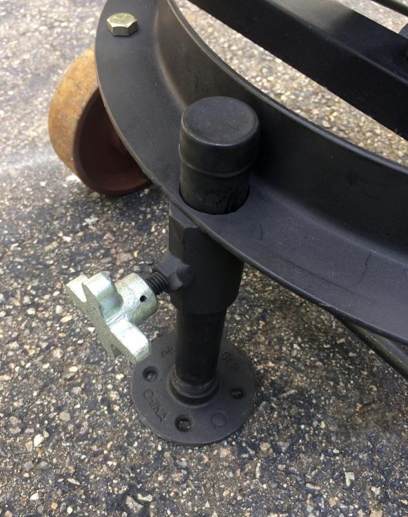
After several months of having to deal with a number of more pressing matters in life, I’ve finally gotten back to modifying and finishing a couple of forges. One is a gas forge that I built last year and works very well, but I’m making a few minor mods to it to enhance its performance, after which I plan to post it on IFI. The other forge is a solid-fuel forge that I just built, which I’m describing here. Both forges are experimental (to me). I use the term “experimental” loosely, since they do NOT represent any brand-new, far-out designs, but I have been playing with a couple of ideas and putting my own spin on a few features, for better or worse. Here’s what my solid-fuel forge looks like, and I’ll explain how I fabricated it. This solid-fuel forge project was inspired by the discovery of a nice antique cast-iron three-leg forge hearth (or “tray” as some of you may call it) for 20 US bucks at Liberty Tool Company, in Liberty, Maine. It was just the bare hearth...no legs or any other attachments. It had some light surface rust, but no pitting, no cracks, and no marks that would have been left by bolts, nuts, or washers around any of the attachment holes, so I think it could have been an NOS part that was cluttering up someone’s barn for a century or so. The underside has an embossed “145-3,” which makes me think it could be a three-leg version of the four-leg Champion Model 145 forge. Any ideas from the antique-forge-savvy crowd out there? Here’s a four-leg Champion 145, as illustrated in an old Champion catalog. The hearth looks very similar to mine, except for the number of legs. After considering how many other projects I “should” have been working on instead of this forge, I abandoned logic and reason and began the process of converting this felicitous ferrous find into a functional forge. One major factor that influenced my design is available space, or the lack thereof. I’m in the process of converting half of a double garage into a small shop area for my metal-related work, and space will be at an extreme premium, especially considering the size of some of the equipment that I want to squeeze into such a small space. Therefore, I wanted both of the forges to be very compact and to be able to roll them out into the driveway for use outdoors. It was easy to restrict the gas forge to a small footprint, but a bit more challenging for the solid-fuel forge. My scheme for keeping it compact was to fit all of the working bits underneath the hearth, with nothing extending out more than a couple of inches, and I wanted to do this without sacrificing any whistles and bells, so there was a lot of kit that had to be stowed in that small space. I had a bit of spare change available for this project, but since there are other things that I like to squander my hardly-earned dollars on, I tried to use surplus and leftover material that I had lying around, although I still had to buy a few items. The first order of business was to add some legs and something to secure the legs. I had some 3/4” schedule 80 black pipe on hand, so I used that for the legs, and I found a round steel duct flange to secure the legs. To add mobility to the forge, I installed a 5/8” diameter axle rod from my scrap bin and a pair of cast-iron wheels from McMaster-Carr. I found an old electric Buffalo Forge blower on eBay for $76 USD plus shipping. I don’t know how old it is...maybe 1960s? It was in working order when I got it, but I discovered that the motor was probably not the original one, and consequently I had to shift the blower housing about 3/16” to re-center the fan in the housing. It has an ordinary, general-purpose 1/8 HP single-phase induction motor, rather than the universal motor that I believe I’ve seen on some old Buffalo Forge Company blowers. I also gave the blower a cosmetic touch-up while I was at it, including re-spraying it with hammer-tone paint like the original. I also replaced the dried-out rubber sleeve around the output port with a piece of 1/8"-thick fiberglass gasket tape saturated with silicone. It really pumps out the air now, with more volume and pressure than I need for this little forge, but I figure better too much than too little, since I can easily control its output with an air gate. It’s also a relatively quiet blower compared to some I’ve heard. The original forge probably would have had legs that splayed out a few inches at the bottom, something like the catalog illustration above, and while that does add stability, at the same time I think the splayed-out legs might constitute a tripping hazard for klutzes like me. Of course, I wanted the forge to be adequately stable. I "think" that I've managed to achieve a comfortable level of stability as a result of the following factors: It doesn’t have a heavy, cast-iron hand-crank blower protruding out to one side a foot or so like the original forge would have had. All of the workings and accessories are installed directly under the hearth, which lowered the center of gravity considerably. The cast-iron wheels added a few extra inches of base width in one dimension, as well as extra weight at the bottom. The “clay” I’m using (which isn’t clay...more on that later) is lighter than fire clay that I’ve used when doing pottery stuff, which probably reduced the weight at the top of the forge. For added stability, I fabricated a drop-down, adjustable 4th leg, and being adjustable, it adapts to uneven surfaces, so I don’t lose that particular advantage of a three-leg forge. Here's the added leg that I installed: Of course, every respectable solid-fuel forge needs some kind of tuyere, so I fabricated one that would connect to an air gate, using the following items: One schedule 40 3-inch butt-weld steel pipe tee. One Schedule 40 3-inch butt-weld 45-degree steel pipe elbow. Two 5.5” OD, .25-inch-thick steel washers (one of which is shown in the photo below). One 4” piece of 3.5-inch OD steel tube. One 2” piece of 3.5-inch OD steel tube (shown attached to the air gate assembly). One sliding air gate. I used an off-the-shelf air gate that I found on McMaster-Carr and modified it a bit. I drilled and tapped holes in it so that it would mount securely to the tee of the tuyere, using four “extended tip” set screws. The extended tips fit into four corresponding holes drilled in the tee, and I used jam nuts to lock the set screws in place. I used the same technique to install a short piece of 3.5” OD steel tube on the other side of the air gate. The connections seem very solid. I also added a drag mechanism to the air gate (more on that later). Butt-weld steel pipe fittings can be expensive, but I found some online that were pretty reasonably priced. Here are the basic items used to make the tuyere: I welded the tee to the elbow, as shown below. Then I welded the two heavy washers together, drilled four mounting holes in the flange formed by the washers, drilled a hole sideways (edge-wise) through the washers to accommodate a clinker breaker shaft, and welded a couple of tabs over the shaft holes, just to add some thickness at those points. By laying a double-pass bead where I welded the flange to the tee, I had plenty of metal for touching up the weld to form a nice radius that almost makes the assembly look like a one-piece casting. The photo below shows the tuyere with the 4-inch length of 3.5-inch tube welded onto the elbow and the ash-dump door and the hinge brackets for the door welded onto the tube (more on the ash-dump door later). Now it was time to mount the tuyere under the hearth. Note that I mounted the tuyere with spring-loaded machine screws. This is one of the “personal touches” that I added to the design. My “theory” is that in addition to shock-heating, shock-cooling, and overheating, one of the reasons that cast-iron hearths develop cracks might be due to different expansion/contraction rates between the hearth and any objects that are bolted securely to the hearth (like a tuyere, for example). I figured that if I used some stiff and relatively heat-resistant springs to mount the tuyere, it would allow the hearth and the tuyere to expand and contract at different rates without stressing the hearth at the attach points. I made sure that the mounting holes were well-aligned with each other and drilled the holes a little larger than the mounting screws to allow a bit of differential movement. On the top side of the tuyere mounting, you can see the clinker breaker, another 5.5” OD washer that I added, and the 3/8” flat-head internal-hex screws for mounting the tuyere, which are countersunk into the washer. I constructed the tuyere grate from a heavy washer that was about 1/4” thick (obtained from a marine chandler) by drilling 8 additional 1/2” holes in it. Please note that I ground off ALL of the zinc galvanizing before welding the modified washer into a small steel NON-galvanized duct flange. I don’t like toxic smoke and fumes from burning zinc (or anything else for that matter). I extended the handle of the clinker breaker downward and installed a brass knob at the end to act as a weight to help keep the clinker breaker centered. As I recall, the clinker breaker itself came from Centaur Forge, and it works just fine, but if I build another forge I might experiment with my own clinker breaker design, since I have a few ideas along that line. To mount the blower, I fitted and bolted a couple of steel angles to the circular duct flange that secures the legs. The blower just happened to fit perfectly, requiring no alterations to the blower base,, other than drilling a couple of holes, but I’ll admit that I didn’t plan it that closely...some luck involved, I think. I constructed a handle for moving the forge, using some surplus 3/4” schedule 80 pipe and a few Kee Klamp® fittings, a couple of which I already had. The set-screw-type fittings allow the handle to be reconfigured or adjusted easily, and I added a sliding flat bar that could be used to hang a few tools on. I installed a steel plate alongside the forge, spring mounted to an existing flange at the edge of the original hearth casting. This plate accommodates the switch box for the motor toggle switch (which is adequately rated for the voltage and current load) and also supports the rod for controlling the air gate. Please note that I plan to keep close tabs on how hot the switch box gets during a long forging session. If it gets too hot, I may install a heat shield or else reposition the switch box...we’ll see. The wires from the switch to the blower motor are encased in flexible metal conduit (FMC) for some protection from impacts, and to the best of my knowledge I installed the appropriate connectors and bushings to prevent chafing where the wires enter and exit the conduit. I did the wiring myself, but I an NOT a professional electrician, so I will not guarantee the correctness, reliability, or safety of the wiring that I did. See the warning below. Warning: Have a licensed electrician do all of the wiring on your forge to help avoid potentially fatal shock hazards. I used a silicone heat-resistant turbocharger hose to connect the blower outlet to the air gate. I can’t remember the temperature rating offhand. I don’t think it will get too hot in this location but I’ll be checking the hose during longer forging sessions to make sure it doesn’t overheat. If it gets too hot, I’ll replace it with some kind of metal elbow. The control linkage I made for the air gate is quite simple: It’s just a straight rod with a knob at the end, which is connected to the slider plate with some springs to provide some stress relief and prevent rattles. The rod passes through the same steel plate that holds the toggle-switch box. Here’s a little twist that I added: To make sure that the position of the air gate’s sliding plate doesn’t drift (and to reduce possible rattling of the sliding door in the gate frame), I drilled and tapped one of the original locking-screw holes in the air gate to 1/4-20 and installed a brass “twist-lock retractable spring plunger” from McMaster-Carr, which presses against the stainless-steel slide and acts as both a drag and anti-rattle mechanism. Adjusting the depth of the plunger determines the pressure against the slider. I added a jam nut to hold the adjustment. The brass plunger tip rides smoothly on the stainless slider and doesn’t scratch it...it just makes a polished streak. The linkage allows very quick and easy changes in air volume, and I will probably add marks on the control rod to indicate favorite settings as I get more practice with the forge. Now, on to the “claying” of the forge. The hearth has the words “CLAY FORGE BEFORE USING” cast into it, which I thought would be advisable to avoid overheating, shock-heating, or shock-cooling the cast iron. I would have used ordinary fire clay, which is cheap and would have worked just fine, BUT I already had a couple of different kinds of leftover castable refractory, including some Kast-O-Lite 30, that was getting close to the end of the shelf life, so I thought I’d use my remaining stock of castable refractory rather than let it go bad. As long as I was using castable refractory, I decided to play with the castable approach and came up with the idea of making separate castings to create a “convertible” forge with two different duck’s nest sizes. It would have an outer casting that would form the larger duck’s nest, plus a removeable inner casting to form the smaller duck’s nest. A dual duck’s nest might not be a new idea within the greater scheme of things, but it was new to me. I made a Styrofoam form for the larger duck’s nest by roughing out some 2” Styrofoam and then chucking it in a drill press and using coarse sandpaper to smooth it while it was spinning. It was a very messy job (Styrofoam dust...I used a respirator), but it created a nice symmetrical form. I coated the Styrofoam with some silicone, thinking that the refractory wouldn’t stick to it very much (which worked ‘reasonably’ well). I adhered the form to the top of the tuyere with some very sticky double-sided woven polyester tape, and I also lined the forge hearth with some polyethylene sheet that I cut and taped to obtain a smoother, snugger fit with no significant wrinkles. The threaded rod was just there to make it easier to pull the form out when the refractory had set. It was time to make the first casting. Note: I followed the refractory manufacturer instructions as closely as possible for all aspects of the casting and dry-out process, from start to finish. Sorry, but I don’t have a photo of when I was making the outer casting. After the initial set or “air cure” of the first casting, I removed the Styrofoam form for the larger duck’s nest, lined the duck’s nest with masking tape to act as a mold release, and made a smaller Styrofoam form for the smaller duck’s nest in the same way that I made the larger one. This time, for the temporary mold assembly, I used a bit of silicone to stick the form to the top of the grate and adhered the grate to the top of the tuyere with double-sided tape. I basically used the same procedure to cast the smaller duck’s nest. After the initial set of the castings, I decided to cut them into smaller sections, which I thought might be advantageous in several ways: First, the cut sections would be small enough that I could put them in a programmable heat treatment oven to follow the official dry-out schedule. Second, the saw-cut gaps would allow expansion and contraction of the refractory castings while the forge is in use without stressing the cast-iron hearth. Third, it could help prevent cracks from developing in the castings while the forge is in use. I dry-cut the pieces with a 7-inch diamond blade. They cut easily, but there was a LOT of airborne dust (be sure to wear appropriate protective gear). After cutting the pieces, I followed the manufacturer’s time/temperature dry-out schedule to safely remove both free and chemically-combined water. WARNING: Always follow the castable refractory manufacturer’s exact instructions for all steps, including the controlled dry-out schedule, to avoid problems that could include potentially dangerous explosive spalling. Because of the castable refractory liner, I plan to keep the forge DRY. If the refractory castings get wet it would require a controlled dry-out process to avoid possible explosive spalling when the forge is used. The need to keep the castable refractory dry might be considered a drawback, since I can’t apply water to the coals for modifying the shape of the fire or allow the forge to get rained on. However, even if I were using some other material instead of a castable refractory for the liner, I would still be a bit leery of using water with a cast-iron forge, since it seems to me that any crack or gap in any kind of liner could allow water to directly contact the cast-iron hearth, in which case I would worry about causing cracks in the cast iron from thermal shock. At least that's my take on it. Someone correct me if I'm wrong. Like many cast-iron items, these old hearths are not perfectly formed, and the surfaces are not totally uniform and smooth, so to maintain a good fit I marked the refractory castings and their locations so that I could place them back in the hearth in exactly the same positions in which they were cast. I coated the cast sections with some left-over ITC-100 that I already had on hand from building my gas forge. Yes, I KNOW...the ITC-100 is unnecessary and expensive, but I already had the stuff and I was curious to know if it might help the fire get up to working temperature a little faster. As usual, I followed the manufacturer’s instructions for applying the ITC-100. The following photos show the cut pieces after they were initially coated with ITC-100. You can see that the inner casting is easily removeable to convert the duck’s nest to a larger size. In retrospect, I should have waited until I used the forge for a few sessions without the ITC-100 in order to get a baseline to compare the performance with and without the ITC-100, but that’s the way it goes sometimes. I get a bee in my bonnet, and off I go. Something to do with “project inertia,” I think. Note: I filled the narrow gaps around the castings with some ash that can absorb a bit of movement as the castings expand and contract. Next was how to deal with ashes and clinkers. I fabricated a custom “ash tray” that fits snugly into the space under the ash-dump end of the tuyere. It’s made from 1/8” hot-rolled mild steel. I welded and ground the corners and installed a piece of 3/4” schedule 40 pipe for a handle with the end welded shut (for looks). It’s not huge, but it holds enough to empty the ash dump several times, and it’s in keeping with the compact nature of the project. I might end up shortening the handle a bit if it gets in the way. I constructed a counterweight-type ash dump door with an adjustable hinge that incorporates a solid rod-end (as opposed to a spherical rod-end). It has only one adjustment, and there is just enough play in the hinge that it automatically makes perfect full contact against the tube every time it closes. Because of the geometry of the door and the angled bottom of the tuyere, it has the advantage of remaining open if I lift it all the way, which allows me to open the door and then (while it’s up out of the way) remove the ash tray in an easy one-hand operation. I ended up adding a little more weight to the counterweight, as you can see in the photo. As to how it all works, I've only fired it a few times so far. It seems to heat up quickly, the air is very easily controllable, the blower is relatively quiet, it cleans up easily, it’s easy to move around, and it’s compact. Despite being compact, the forge is hefty enough that I ask for help if I need to lift it into my truck (I want to avoid a second hernia operation), but once it’s back on the ground I can roll it around easily. I will try to get some photos of it in operation over the next week or so and post them. Here are a few images of the forge from different angles: Some of you might consider this project to be overkill for a little solid-fuel forge, but I’m totally unrepentant. I had fun designing and building it and learned a thing or two in the process. I’m one of those guys who likes making tools as much as using them. You might say that I’d rather take the back road and enjoy the scenery, even if the expressway is faster (not the best analogy, but you get the idea). It would also have been easier and faster to fabricate the legs and other framework by doing more welding and using fewer fasteners, but I think it was worth the extra effort to use fasteners in several places, since it allows future modifications (and corrections) to be made more easily. If I were to build another solid-fuel forge, I’d probably build the hearth and firepot from steel, which would be less work than adapting everything to the old cast-iron hearth, and of course steel is much more forgiving, more easily modified, and more repairable than cast iron. Still, it was an interesting challenge to see what I could do with an antique hearth. I didn’t really keep track of my expenses for building this, which would have been difficult anyway, since I would have had to factor in the various leftover materials that I already had on hand. In any case, you can certainly build a forge that works very well for considerably less time and expense, assuming that your prime objective is to quickly get a forge up and running. There are still a couple of improvements that I will probably make: I might fabricate a removeable windbreak/sunshade that would also incorporate about a one-inch raised ring around the hearth to prevent wayward lumps of coal from straying too far from the herd, jumping the fence, and ending up on the floor. The hearth currently has a raised edge, as you can see, but it could stand to be a touch higher. I’m also thinking about modifying the handle assembly to include an adjustable-height tool rest...très chic in fashionable blacksmith circles this season, or so I’ve heard. I made such an animal for my gas forge, and it’s really handy. As mentioned, I will try to keep an eye on how hot the components under the forge get, especially during longer forging sessions. DISCLAIMER: I am NOT a professional blacksmith, engineer, or electrician, and I built this forge as a personal project and experiment. I DO NOT guarantee its safety, reliability, or functionality, so if you copy or adapt any of my methods, or the features, materials, or characteristics of this forge, it is entirely at your own risk. I welcome your feedback and suggestions. I'll post a few pix of it in use as soon as I have a bit of free time, which is kind of a rare thing for me these days. Cheers, Al (Steamboat)


-
Thanks for checking, ede. I did finish building the forge, but our Maine winter and several high-priority projects intervened, so I was only able to give the forge a very brief trial, which was very encouraging. Now that the weather is decent and I'm getting caught up on a couple of other things, I plan to make a few minor "adjustments" to the forge and fire it up again (hopefully in the next week or two) and post some photos of the completed forge in operation. I always seem to start about three times more projects than I have time to finish, but at least I'm never bored, and I actually do complete some projects from time to time . Steamboat
-
Trenton Anvil? (or A&H or ?)
Steamboat replied to Steamboat's topic in Anvils, Swage Blocks, and Mandrels
Like you, I used an extra-long bit and drilled all the way through the wooden stand, so the threaded rod does go all the way through it. The fact that it also passes through the embedded steel angles just adds some (probably unnecessary) structural strength. The power line eyebolts you mentioned are a good idea for saving a few bucks. I'm assuming you're talking about the ones used to secure wire rope braces to the pole, or something similar. Steamboat -
Trenton Anvil? (or A&H or ?)
Steamboat replied to Steamboat's topic in Anvils, Swage Blocks, and Mandrels
Thanks. I just gave it its first workout on the new stand, and it's solid. I adjusted the surface of the wooden stand for maximum contact with the bottom of the anvil using a simple old technique: I rubbed graphite on the bottom of the anvil and moved it around on the wood to mark the high spots, and then ground off the high spots and repeated that several times until it was contacting the wood quite evenly. It might not be all that important, but I figured that it wouldn't hurt. I'll probably make a steel stand for the next anvil (whenever it materializes) and include a pair of small wheels that it could tip back on for moving it around the shop, but it would not rest on the wheels when upright, since I would want the stand to be firm against the floor. A tool rack could probably double as a handle for trundling it around. Steamboat -
Trenton Anvil? (or A&H or ?)
Steamboat replied to Steamboat's topic in Anvils, Swage Blocks, and Mandrels
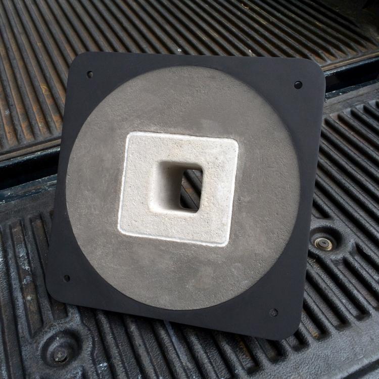
I did a bit of cleanup work on the Anvil (Trenton, ca. 1918). I didn't remove any metal from the top face other than burnishing off the light surface rust with a Scotch-Brite pad. I did a little light touch-up along the edges and also dressed the chips along a section of one edge (on the far side, not really visible in the photo), making a pretty decent 45-degree bevel, which could be useful. I'm also putting some finishing touches on a stand for it (below), which I made mostly from scrap lumber and metal I had lying around. I still plan to add a small tool rack, as well as a floor flange around the bottom. The top and bottom angle pairs are recessed into notches in the wood, which secures them so that they cannot be pulled out of place. I also used some pieces of reinforced-rubber conveyor belt as spacers between the hold-down channels and the anvil. The rubber spacers and the wooden stand seem to have quieted it down a good deal. Now, instead of a loud 'clang,' I get a much more subdued 'clunk,' which should help keep the neighbors happy. I'm keeping my eye out for a larger anvil, but this little 75-pounder is a welcome addition to my slowly-growing blacksmithing kit, and the price was right. Steamboat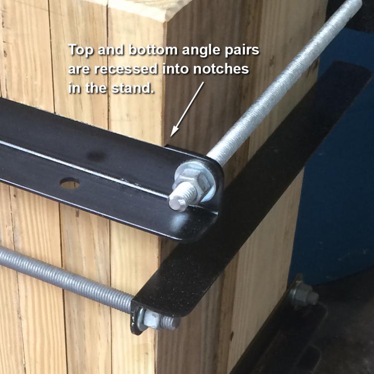

-
I'll take that as a compliment. Muchas gracias. I hope to get this thing fired up in the next few days, barring any major glitches. I plan to post some photos in the gas forges section. Actually, it's probably an overly complex design, but it's been fun to work on...mostly. Steamboat I just may give that a shot...sounds like another good experiment. I could even paint some stripes on a piece of insulating firebrick with the two solutions and heat it with a propane torch, or just toss the brick in the forge and watch what happens to it. Steamboat
-
Thanks for the reference. I read about his use of stainless screws to connect a piece of Kaowool board to a horsehoe, and I've noticed how ceramic blanket material can be formed into shapes to some degree. I was initially thinking that I might secure the insulating board in the end-bells with some kind of stainless fastener, but it wasn't necessary in this case because of the design of the forge. When the forge is assembled, the board should be held securely between the curved end-bell and the insulation material in the forge body itself, so it shouldn't be able to move in any direction. At least that's my theory. Here's a photo of one of the end-bells (the one with the vent/pass-through port). The end-bell is entirely filled with insulating material, with no open areas. I used a bit of Inswool Moldable caulk around the edges of the rigidized board as part of my experiment, and I'm also experimenting with a thin coating of refractory mortar on the board. I think it was Derby 3000 Hi Temperature Mortar that I used on this end-bell, but I'll have to check my notes. Before installing the board in the end-bell and coating it with mortar, it was heated to drive off any binders and also to set the rigidizer. All exposed insulating surfaces will be coated with ITC-100. As usual, I followed the manufacturers' instructions and safety guidelines when using these materials, including the use of personal protective gear, and I'll add my 'experiment' disclaimer below. Disclaimer: The methods and designs presented here are intended only as an experiment and not as a recommendation for their use. I do not warrant the safety, efficiency, applicability, or any other characteristic of these methods or designs, and their use is entirely at your own risk. Steamboat