Steamboat
Members
-
Joined
-
Last visited
Everything posted by Steamboat
-
@Candyman, I never have gotten around to making the upsetter blocks...too many other projects going on. I have, however, used the vise a number of times, and it's nice to have both hands free when you need to do multiple hold-and-reposition operations, especially with hot metal, when timing is important.
-
HCO41, be sure to re-read all of my postings and revisions in this thread, just to make sure you understand my point of view. If you have any questions, feel free to PM me. Thanks, Al (Steamboat)
-
Thanks for the Drill Doctor suggestion. I'll have to have a look at their models. I've been working on our old house all day (no rest for the wicked, I guess). And I might do a little blacksmith work tonight to fabricate an old-fashioned looking support bracket for a cracked beam. Al (Steamboat)
-
Frosty, regarding the diamond wheel grit. I did some checking to refresh my memory. I had started out with a 120-grit wheel (even though it appears quite a bit coarser in the photos), and as mentioned earlier in this thread I thought that a finer grit would have been better, so I decided later to change to a 220-grit wheel. As you said, I think a guide or device could be built that could control or limit pressure against the wheel, along with other factors. There are a lot of possible configurations. Perhaps some adjustable spring-loaded approach? It could be fun to design, but as usual, I always have more projects and ideas than available time to play with them. My current big project is restoring our 225-year-old house. I'm doing most of the work by myself, since hiring a crew to do the work is beyond our budget. It's amazingly time consuming, but I enjoy working on it, and as a result I get a lot more exercise than most retirees like me manage to get at my age. I'm at the point in the restoration process where I'm looking at reproducing some of the old hardware (door latches, hinges, etc.), which will give me an excuse to do some more blacksmithing...and save some money.
-
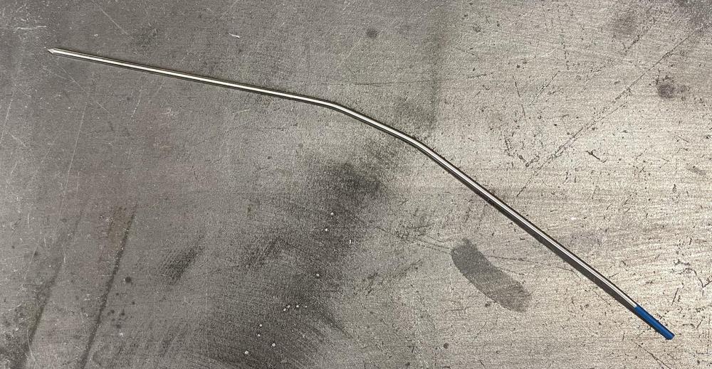
I don't remember what grit the diamond wheel is, but it is a lot finer than it looks in the photos, probably because of the way the surface makes random reflections, making the granules look farther apart. The points should be ground longitudinally (lengthwise, with grind marks in line with the electrode), according to all of the instructions I've read. Tungstens can snap very easily, but they can also be bent. To demonstrate, I just went out to the shop and bent this 2% lanthanated tungsten in a couple of places, cold, (while wearing appropriate protective gear, of course, in case it snapped).
-
bubba682, as you alluded to, I've seen some sharpeners that didn't have much, if any, adjustability, although I can adjust my experimental jig to produce a fairly wide range of point angles/lengths. You mentioned using a diffuser and extra stick-out for pipe welding. I'm not a professional welder, but I've done a fair amount of welding on my own projects over the years, and I've recently started using gas lenses/diffusers. I think that my welds are coming out more consistently clean, and since the smoother gas flow allows some extra stick-out, I have a little better visibility of the weld pool. Maybe it's the improved visibility (or maybe it's just from having more practice), but I seem to be accidentally dipping my tungsten less often. By the way, Cape Breton Island looks like a gorgeous area. We've spent a good deal of time in New Brunswick, as we used to go to places like Campobello Island, Grand Manan Island, etc., on a regular basis, but we haven't yet made it to Nova Scotia. It's on our bucket list of places to go.
-
Thanks for the comments, Frosty. Tungsten is hard, but the coefficent of friction between a tungsten electrode and a grinding wheel can still be significant, at least in my experience. I just looked through the leftover parts from my earliest experiments...and at the contents of my used-electrode bin...and the sight of several bent and broken tungsten electrodes refreshed my memory of experimenting with a fixed/restrictive guide combined with a 'dragging' rotation direction. I can recall the wheel pulling an electrode(s) through the guide and breaking it. The fixed guide allowed forces to build up in a fraction of a second. I think a drag-sharpening situation could be different if MANUALLY sharpening an electrode by hand, WITHOUT using a fixed, restrictive guide like mine, since the pressure against the wheel and the resultant pulling and bending forces could be limited by the user when holding the electrode. -------------- Disclaimer: I am not an expert. This post is not intended to be an endorsement of any product or idea depicted or described here. I do not guarantee the safety, efficacy, or applicability of my experimental prototype electrode sharpener device that is depicted or described in my posts in this thread, or the use of any product with that device. Any use of my design or methods is entirely at your own risk. Use appropriate personal protective gear at all times. My posts are not intended as instructions for grinding tungsten electrodes, but only to show the stages in the development process of my experimental prototype electrode sharpener.
-
I suppose there could be ways to reverse the direction of a grinder wheel relative to what you're working on. HOWEVER, if you feed an electrode through a restrictive GUIDE (such as the one shown in my experimental device in this thread) into a wheel that is rotating AWAY from the point of the electrode instead of TOWARD the point of the electrode, there is a good chance that the electrode could be grabbed by the wheel and drawn/pulled through the guide, which could bend and break the electrode and throw sharp pieces of metal around, etc., which could be dangerous. It's been quite a while, but I seem to recall that happening when I tried something like that. Disclaimer: I am not an expert. This post is not intended to be an endorsement of any product or idea depicted or described here. I do not guarantee the safety, efficacy, or applicability of my experimental prototype electrode sharpener device that is depicted or described in my posts in this thread, or the use of any product with that device. Any use of my design or methods is entirely at your own risk. Use appropriate personal protective gear at all times. My posts are not intended as instructions for grinding tungsten electrodes, but only to show the stages in the development process of my experimental prototype electrode sharpener.
-
Thank you. It's been quite a while since I've posted on the forum, as I've been swamped with a dozen big projects for some time...house restoration, archaeology project, freelance writing, property sale, etc., etc. Anyway, to answer your question, I did the welding with my Millermatic 251 MIG welder, using a 75/25 argon/CO2 mix. For the welds on the pipe and washers, I just tacked the parts to a simple turntable I cobbled together, and then rotated it slowly as I welded it. Someday I might actually build or buy a nice variable-speed motorized rotator.
-
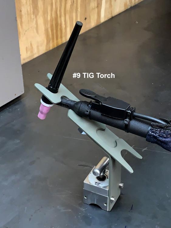
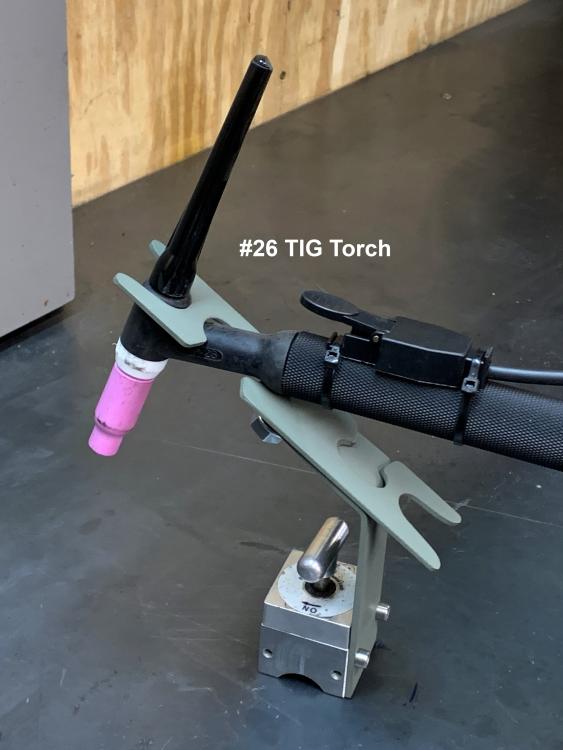
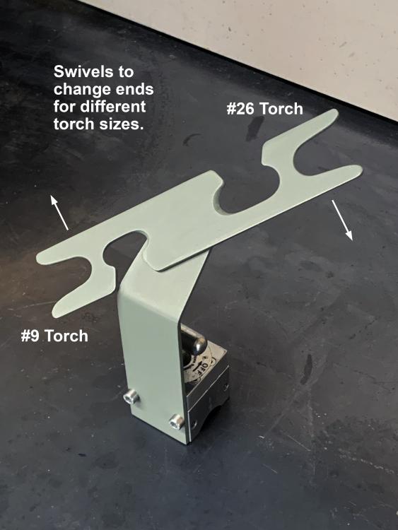
I've been incredibly busy this past year and haven't done much in the way of blacksmithing, but I have done a few welding projects. Here's a little gadget I just finished up to make my TIG welding a bit more convenient. I borrowed a few ideas from torch holders I’ve seen online. My variation on the ones I’ve seen was to make two sets of cutouts, one for a larger TIG torch and one for a smaller TIG torch, which could be rotated to select the size. I don’t think that’s a new idea, as there are almost certainly people who are smarter, faster, and better looking than I am who thought of it first, but here it is. Two opposed pairs of Belleville disc springs provide adjustable clamping force to maintain the selected position with enough resistance to keep it from rotating when in use, but still allow it to be rotated by hand. The multiple Belleville disc springs provide a wider, less-sensitive adjustment range than a single Belleville spring. The switchable magnet makes it easy to reposition, and it can drop any beard of ferrous debris that it might grow. The magnet can also serve double-duty as a setup magnet. As with other magnetic bases, it’s much more strongly attracted to a thick steel bench top than a thin one. If the steel top is too thin, the magnet might not hold adequately. My usual disclaimer: I do not guarantee the safety, efficacy, or applicability of the devices, designs, or ideas I have described here. Any use of these devices, designs, or ideas is entirely at your own risk.

-
Actually, I would keep them just because I like the way they look. To me, it's an appealing shape...maybe for part of a future sculpture, or maybe just to look at once in a while. Also, you could use them for letters. If you cut off part of one of the legs, you could make a "J" and turn one on its side for a "C" (in case you know anyone with those initials). A "u" or "n" or "m" or "w" are other possible characters...or maybe a very large "O." Or maybe legs for a trendy coffee table? Al (Steamboat)
-
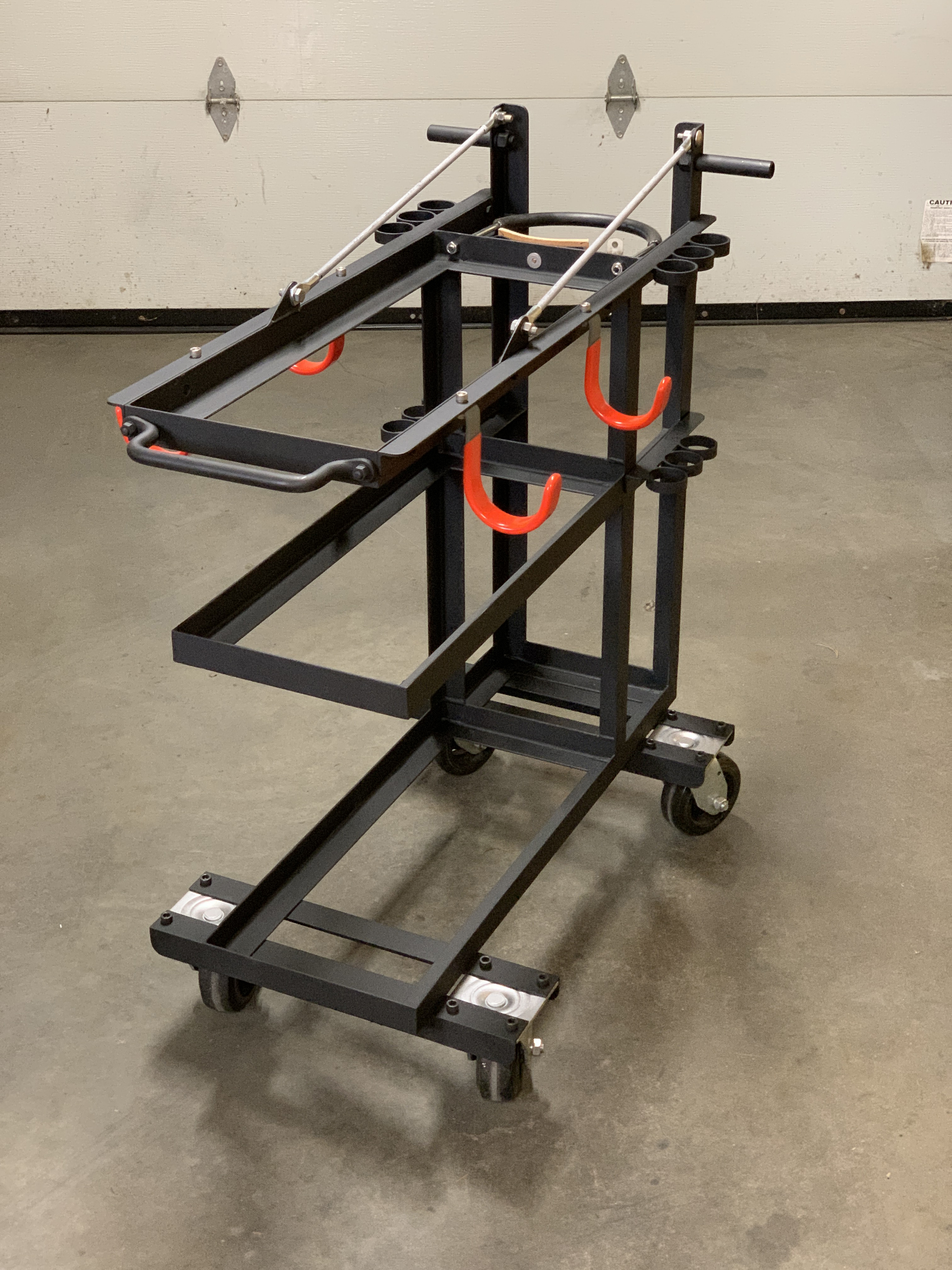
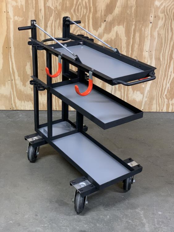
Thanks, Arkie. The support/suspension rods were an idea I had to add rigidity to the top shelf without blocking access to the middle shelf. The cable hooks do block access to the middle shelf to some degree, but if I decide that they are causing interference, a hook can be repositioned easily just by drilling a new mounting hole. The hooks could even be mounted on the back of the cart if necessary, although I'm trying to limit the front-to-back length of the cart so that it doesn't stick out too far when backed up against a wall. As mentioned, space is at a premium in my small shop. Al (Steamboat)
-
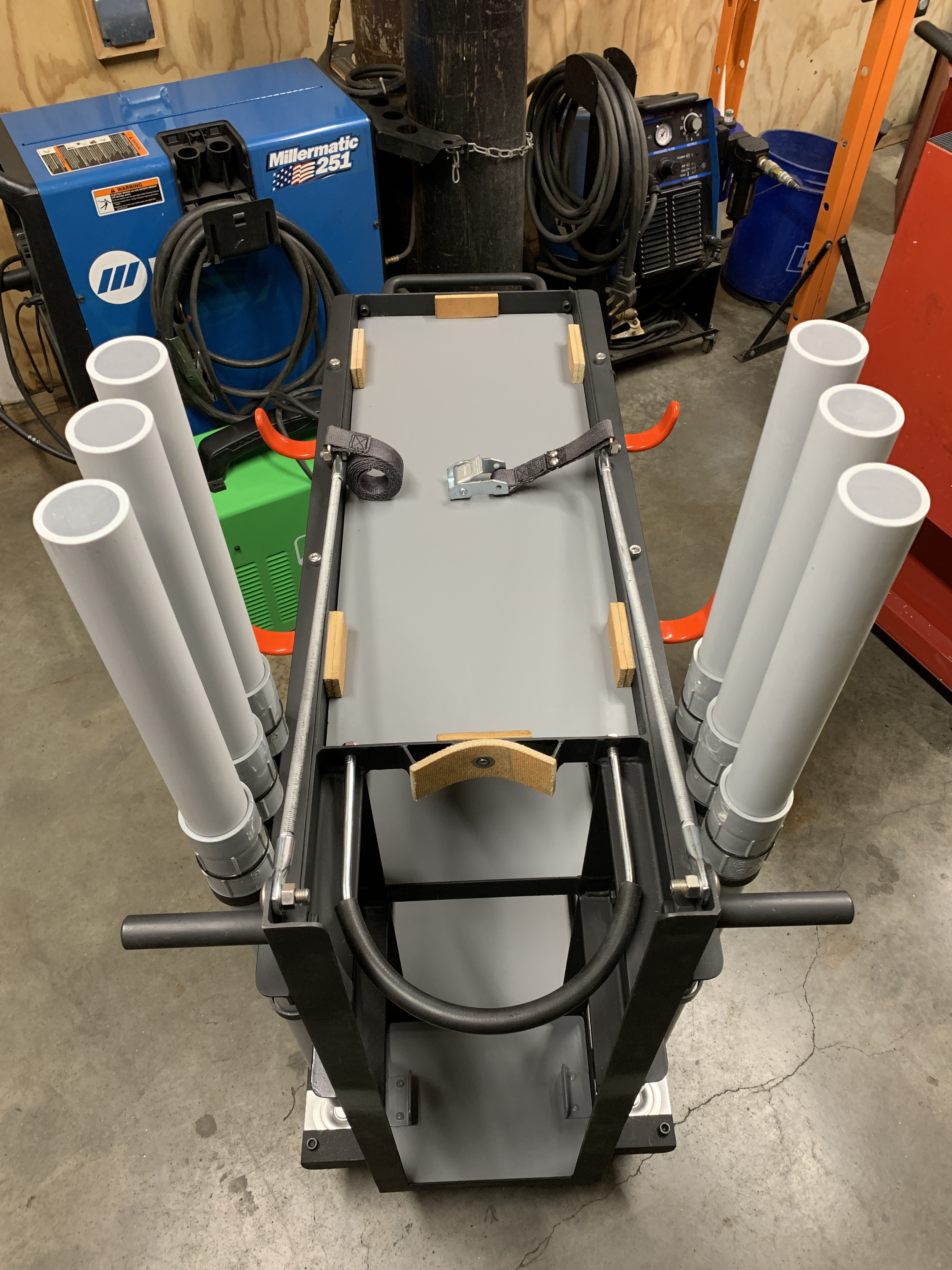
Slight correction: The filler rod tubes were made from schedule 40 PVC conduit, not schedule 80, although schedule 80 would have worked fine, too. Schedule 40 is certainly thick enough to make a durable tube, and you'd lose some interior volume if you used schedule 80. Al (Steamboat)
-
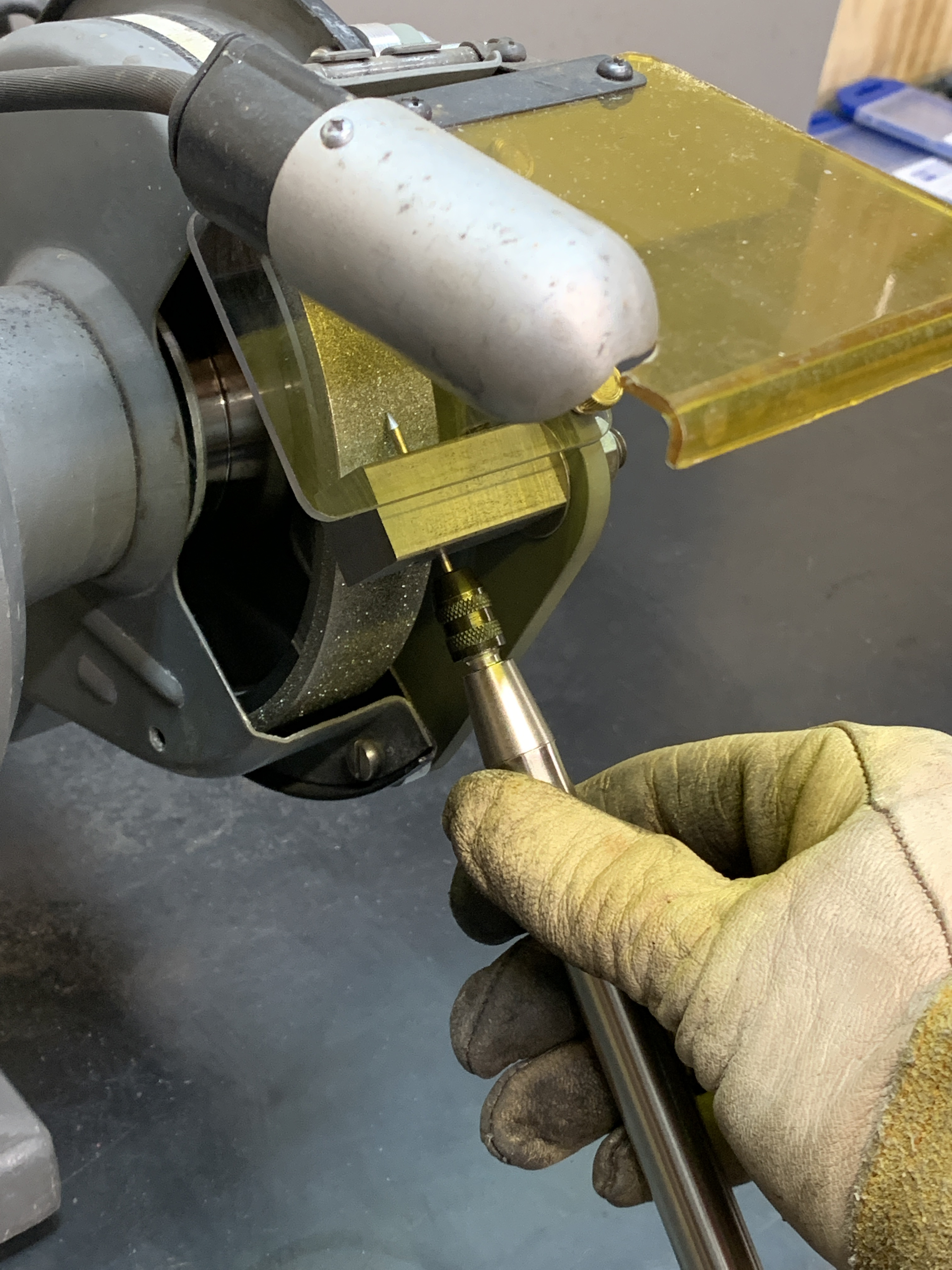
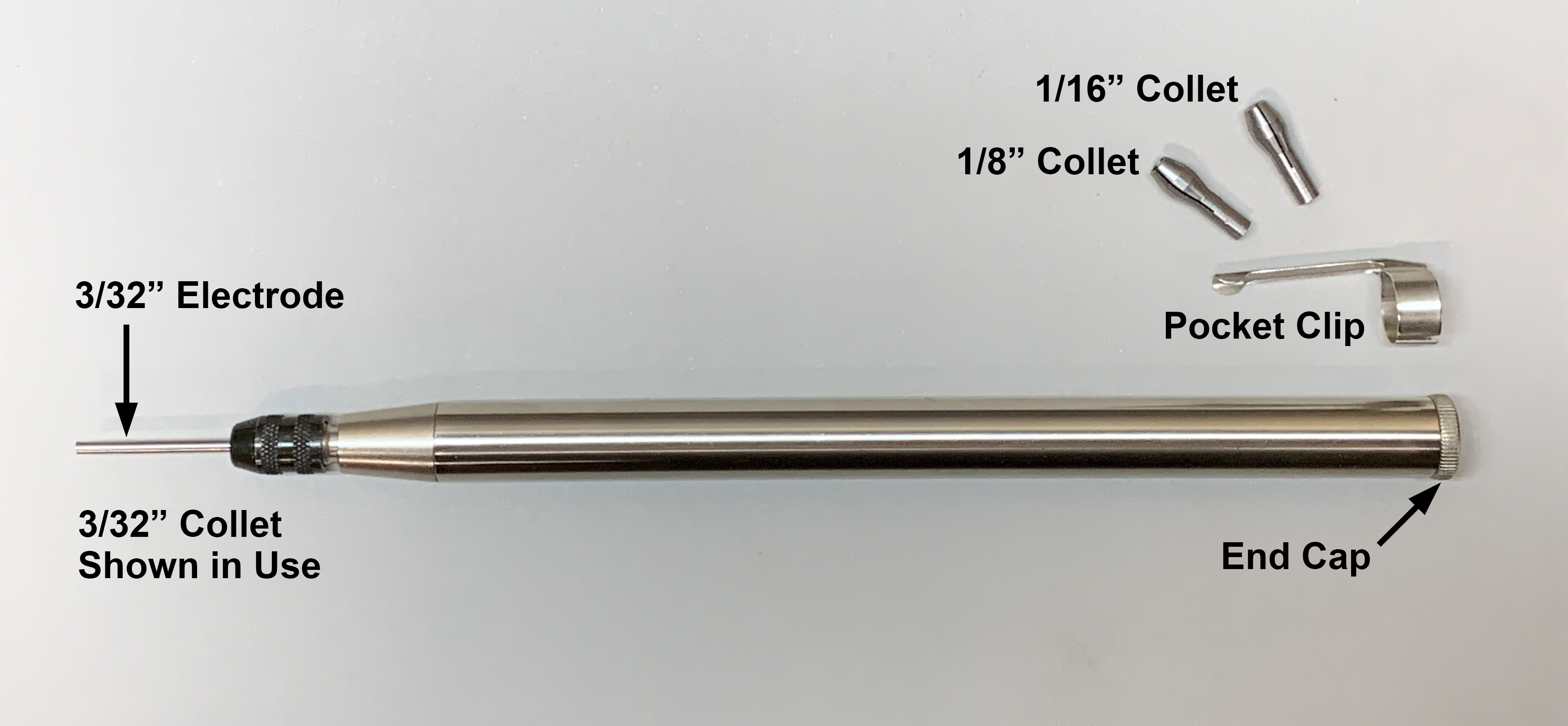
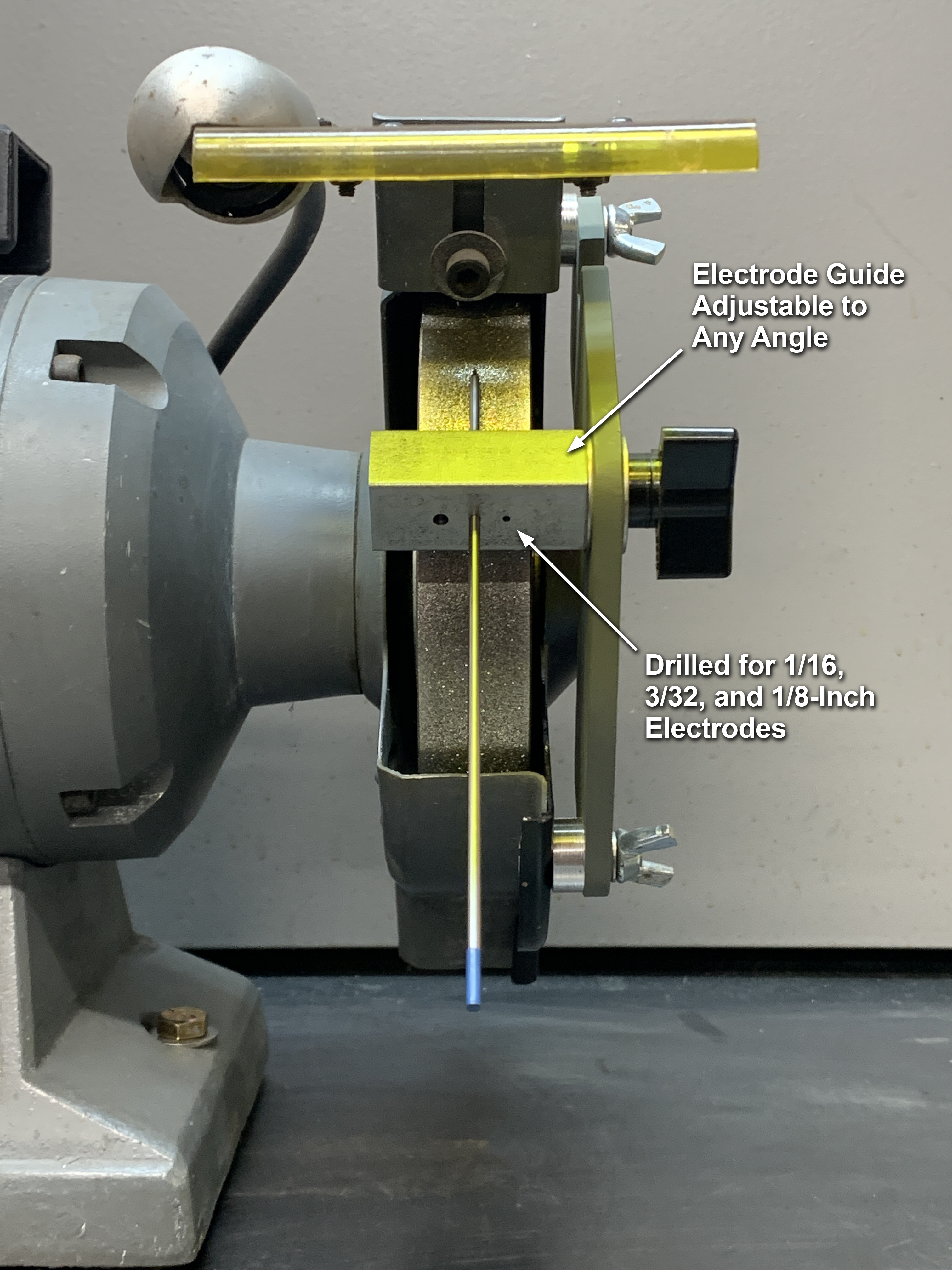
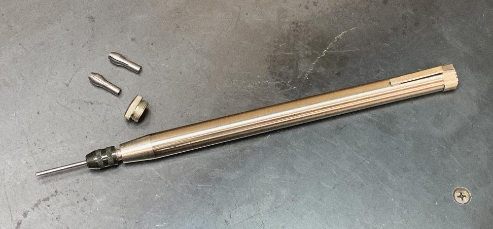
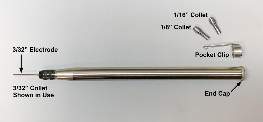
Another update: I recently bought an electrode holder to try using with my experimental prototype electrode sharpener. In the photo below, the holder encloses the electrode almost up to where it enters the guide hole of my sharpener. The holder came with collets for 1/16, 3/32, and 1/8-inch electrodes. The collets can be stored in the holder when the holder is not in use. I can rotate the holder easily with gloved fingers, which I really like, as I feel that it gives me more control over the grinding process. The pocket clip can be removed if desired. Note that I always tighten the collet firmly and screw the end cap onto the holder before grinding an electrode to prevent the electrode from coming loose or getting pushed out through the end of the holder. It seems to me that using this electrode holder with my experimental prototype electrode sharpener could improve safety in case of kickback. Grinding electrodes is never totally safe, however, and I will continue to take my usual precautions while doing further testing. In the photo below, I've set up the holder for grinding a 3/32" electrode, with the end cap in place and the collet tightened. The other collets and pocket clip that came with the holder are also shown. Disclaimer: This post is not intended to be an endorsement of any product depicted or described here. I do not guarantee the safety, efficacy, or applicability of my experimental prototype electrode sharpener device that is depicted or described in my posts in this thread, or the use of any product with that device. Any use of my design or methods is entirely at your own risk. Use appropriate personal protective gear at all times. My posts are not intended as instructions for grinding tungsten electrodes, but only to show the stages in the development process of my experimental prototype electrode sharpener. Suggestions are always welcome, of course. Al (Steamboat)


-
Thanks, Daswulf. As mentioned, I think it would have been easier to fabricate the cart with square tubing instead of angle, but I'm pretty pleased with the way it turned out. Cheers, Al (Steamboat)
-
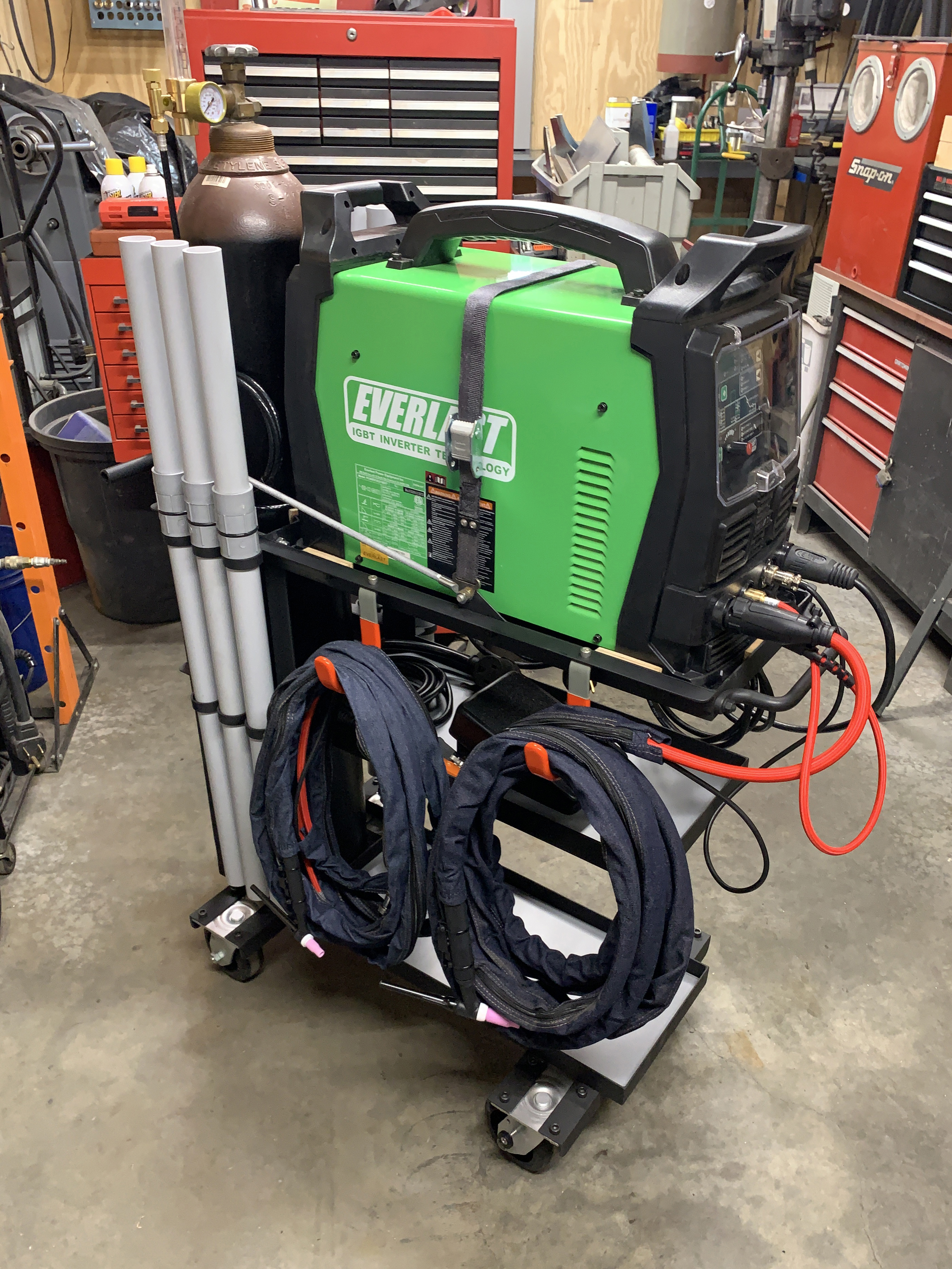
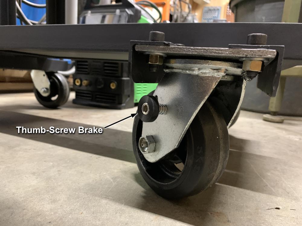
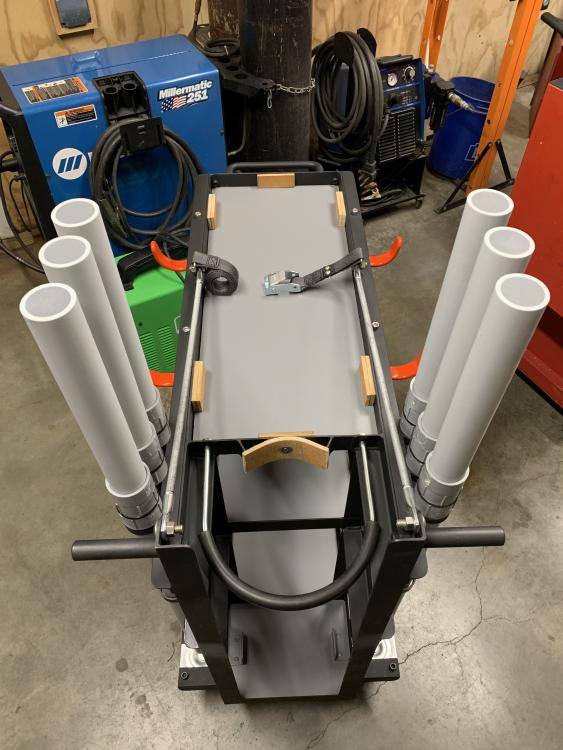
I just fabricated a we80lding cart (or "trolley" if you prefer) for my new TIG welder. I gave my old AC/DC TIG setup to a contractor friend who helps me out on occasion. I had about 60 feet of steel angle that was originally intended for a project that never materialized, and I had half a dozen swivel casters left over from when I built a dock some years ago, so I didn’t have to buy much stuff to build this. It would have been easier to fabricate from square tubing, but I wanted to use what I had on hand and save a few bucks. My little shop area is so crowded that I needed as much maneuverability as possible for the cart, and using four swivel casters makes it very maneuverable. When the new welder arrived, I discovered that the new model is longer than the previous year’s model, so I had to lengthen the top shelf a bit. The shelf bottoms are 1/8" steel and are removeable to make future modifications easier. I mounted a handle on the front of the cart, plus a pair of handles on the back of the cart that sort of act like handlebars and make the cart very easy to maneuver around. The side rails of the top shelf consist of four pieces of steel angle (one 1.5" x 1.5" x .125" and one 1" x 1" x .125" on each side) that extend unbroken all the way to the posts at the very back of the cart, and I added two 3/8" all-thread "suspension" rods for even more support. The middle shelf is for accessories and won't be carrying much weight, and its rails also extend unbroken all the way to the posts at the back of the cart. I’m reserving the bottom shelf for a cooler unit. I’ve been researching liquid coolers for TIG torches, and eventually may build or buy a cooler. I like the open design of the shelves, with no posts up front to get in the way, as I think it allows for a wide variety of configuration and usage options. My shop floor and the area of the driveway where I would be using the welder are quite level, but I decided to add brakes to the casters anyway. I installed thumb-screw brakes on the front casters (see below), and I plan to add brakes to the rear casters as well. The argon cylinder is secured with a large U-bolt with a piece of high-pressure air hose on it for padding, and the cylinder is pulled snugly against a V-shaped pair of angles welded to the frame, with a chunk of conveyor belt for padding. The cylinder doesn't contact the screw that holds the padding on the frame, as I designed it with a gap in the middle. I don’t like cylinders to bang around when moving a cart, and this setup holds the cylinder securely. I also added some pieces of conveyor belt as spacers/bumpers to fit the welder snugly in the top shelf, so that it can't slide around. I also installed a strap to further secure the welder. I made a set of low-cost filler-rod tubes from 1-1/4” schedule 80 PVC conduit schedule 40 PVC conduit. I fashioned internal plugs for the top and bottom ends out of slices of solid PVC rod, sanded them to fit snugly, and solvent-glued them in. Note: The tops might look open in the photos, but that's because the internal plugs are darker than the PVC conduit. The internal plugs eliminated the need for PVC fittings at the top and bottom, which allows me to slide the tubes in and out of the rings that I welded on the shelf rails. The tubes have male and female thread adapters where the top and bottom sections connect, and by using a thick O-ring, the tops screw on easily and stop against the O-ring before the threads have a chance to start binding. I just had to sand off the raised letters on the edge of the female adapter to allow a tight seal against the O-ring. These tubes should be durable, and they cost less than the off-the-shelf plastic holders that I’ve seen. I suppose if one wanted to get fancy, one could create a chamber at the top of each tube to hold a little bag of desiccant gel. Future modifications might include a short metal tube in which one could place short pieces of filler rod that might still be hot, and maybe a rest for the TIG torch. I might also try to figure out some sort of drawer or bin for the accessories. In the meantime, it is working well. I'm always open to suggestions for improvements. Disclaimer: As always, I do not guarantee the safety, efficacy, or applicability of the devices, designs, or ideas I have described here. Use at your own risk. Al (Steamboat)


-
Things can get switched around easily when translating between languages. Cheers, Al (Steamboat)
-
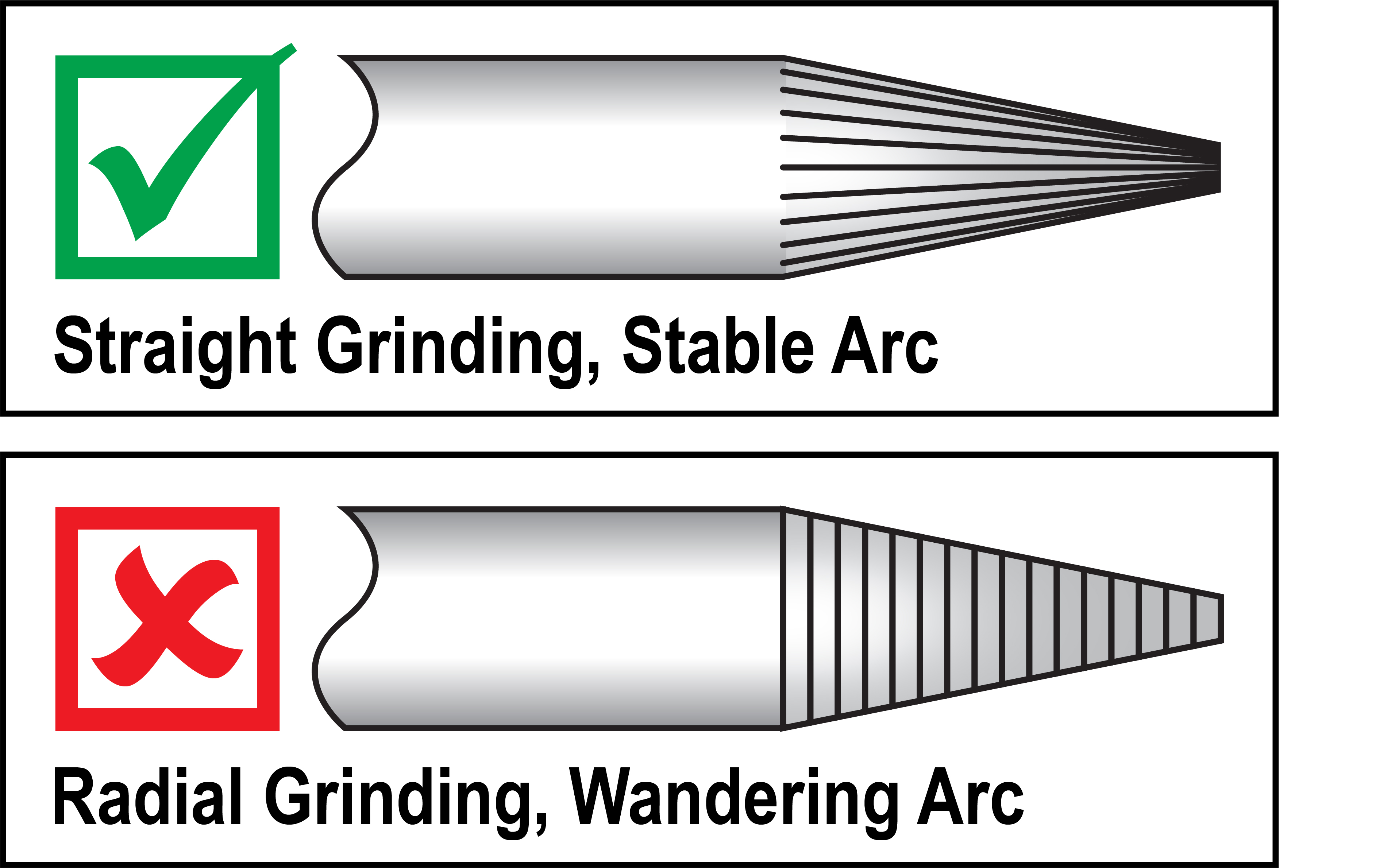
As I mentioned, straight grinding marks on a tungsten electrode point should produce a more consistent, stable arc than radial grinding marks. It's interesting that such a small detail can make a significant difference. By the way, I just ordered an electrode “wand” for holding tungsten electrodes while grinding them. The wand I ordered should be more than long enough to contain/cover the entire electrode right up to the electrode guide in my prototype device, and I think that the diameter of the wand should probably be a reasonable size for rotating the electrode with gloved fingers while grinding. I should receive it sometime in the next week or so, and IF I like it, I'll post a photo and the brand/model information. Disclaimer: The device I have described in my posts in this thread is an experimental, prototype device, I do not warrant the safety, efficacy, or applicability of this device, and any use of this design or device is entirely at your own risk. Use all appropriate personal protective gear when using this or other tools. My posts in this thread are not intended to serve as instructions for grinding tungsten electrodes; they only provide a description of an experimental prototype device in its early development stages. Al (Steamboat)

-
Deimos and Nodebt, I agree with both of you that some kind of handle/knob/holder for the electrode is worth investigating. The holder could act sort of like a larger-diameter "end" to the electrode, which could be safer than a bare electrode in the event of a possible kickback. Of course there's still the chance that an electrode might break into pieces if kicked back. Perhaps a holder could be used that contains (encapsulates) the entire electrode except the portion extending through the electrode guide. I've seen a couple of holders that are reminiscent of an extra-long pin vise, with separate collets for different electrode sizes, and yet small enough in diameter that one could twirl it easily and quickly with gloved fingers while grinding the point. I may order one of those and try it out. By the way, regarding your suggestion, I have a Drill Doctor, which has worked well for drill bits, and I think I also have a drill bit sharpening attachment for a bench grinder in a drawer somewhere. I've never looked into modifying those for other purposes, but who knows? The nice thing about using a diamond wheel on a bench grinder is that the grinding marks run parallel to the electrode, which might sound like a minor thing, but (as you might already know) straight grinding marks help prevent the arc from wandering, which can happen with spiral or perpendicular grinding patterns. Thanks for your suggestions! Al (Steamboat)
-
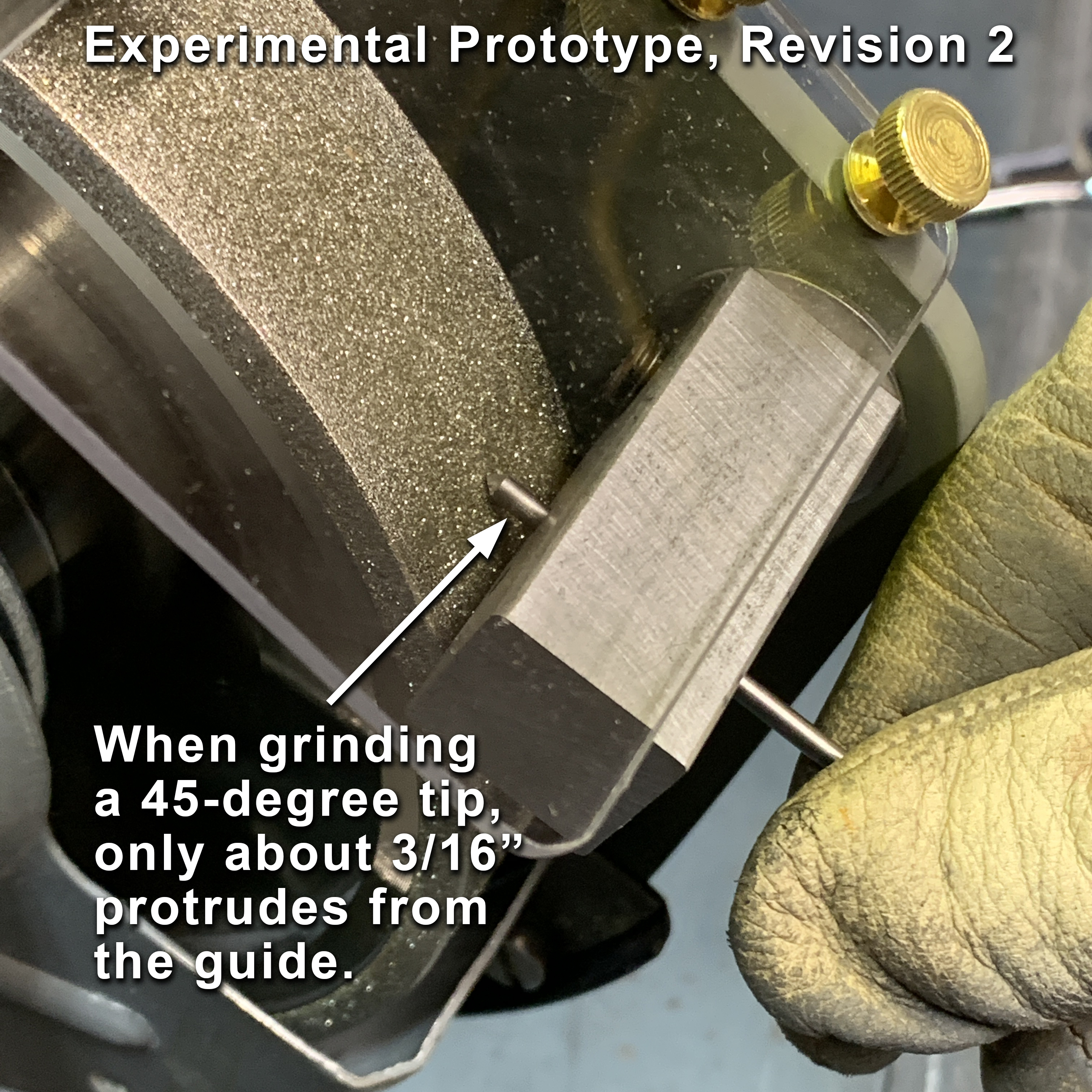
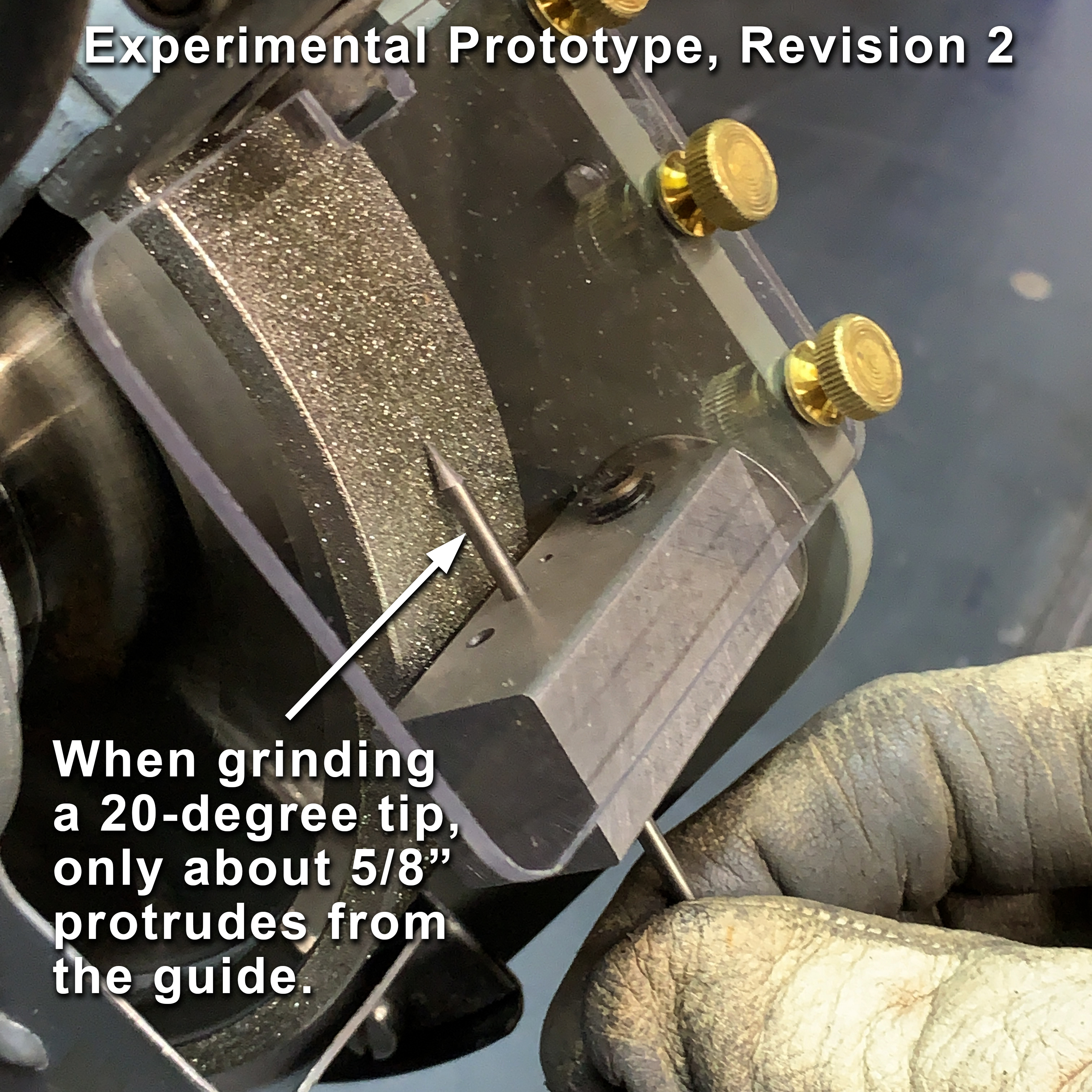
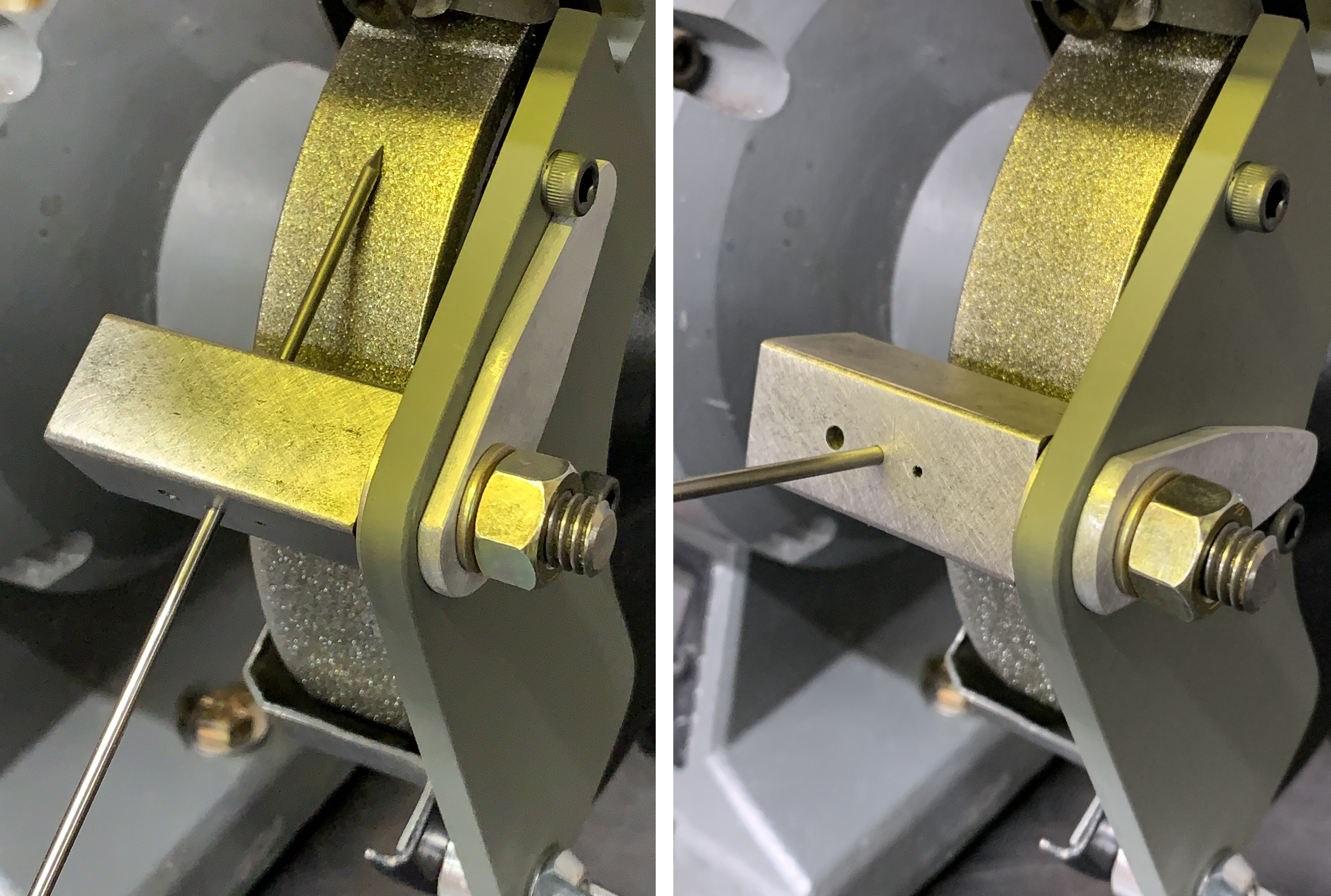
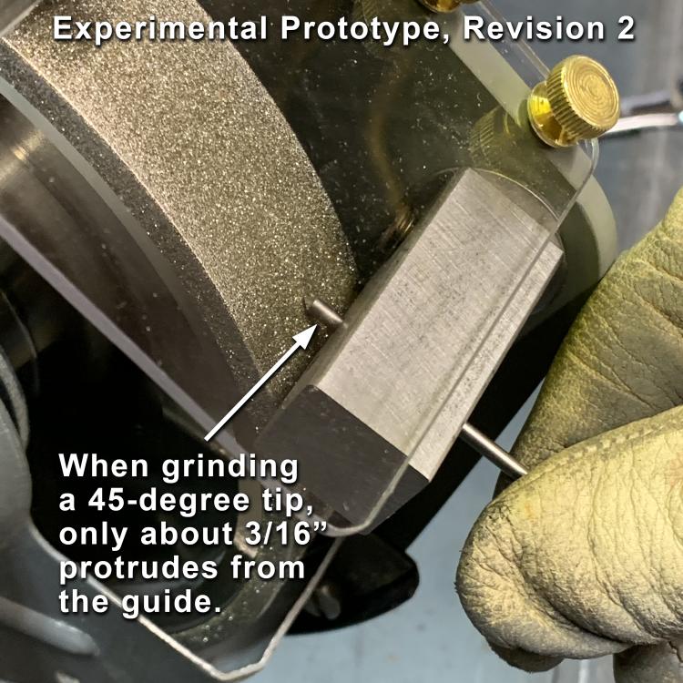
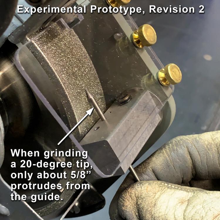
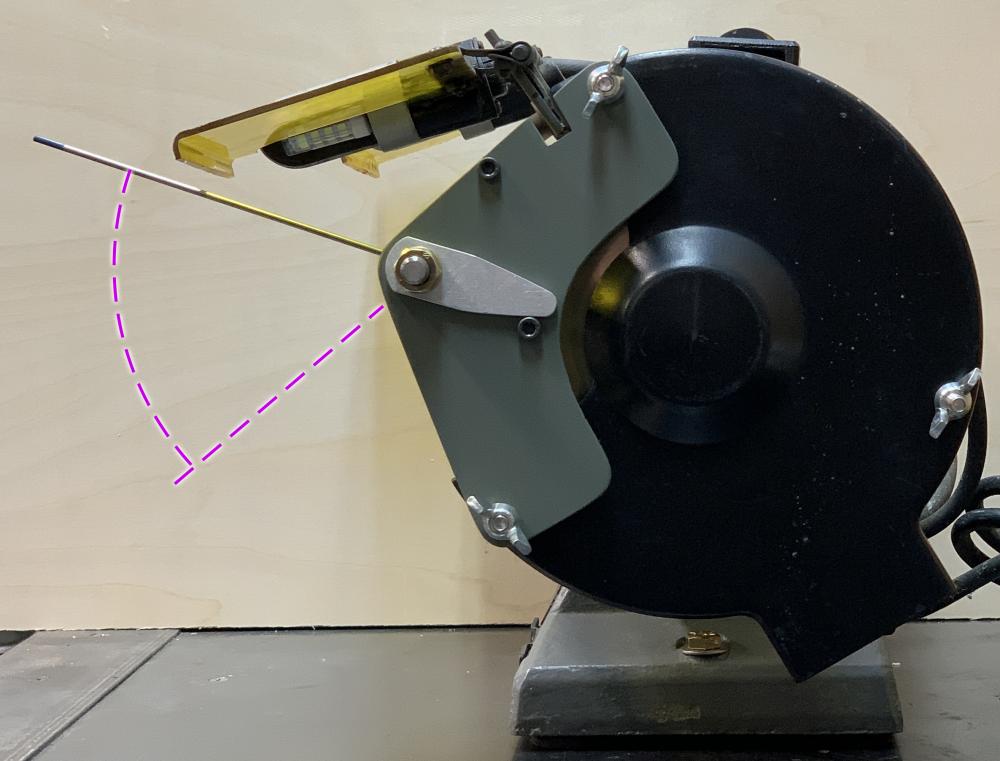
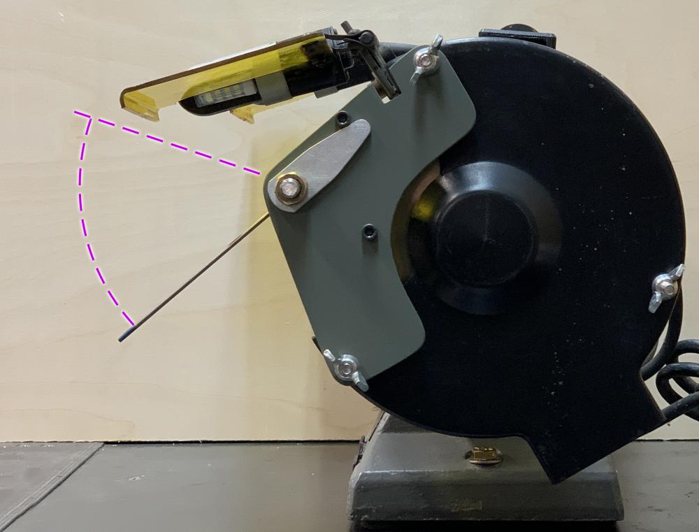
Deimos, thanks for your feedback. I assume that you are talking about how an electrode is oriented relative to the rotation direction of the grinding wheel during the grinding process. Most welders that I've observed grind tungsten electrodes pointing against the rotation of a bench grinder wheel, and most of the instructional material (that I've seen) also shows it done that way (see example links below). I think that visibility might be one factor in the choice of direction, and there could be some other factors involved. Bottom of page 8 in this document from Miller Welders: https://www.millerwelds.com/-/media/miller-electric/files/pdf/resources/gtawbook.pdf At about 2:36 into this video from Miller Welders: https://www.youtube.com/watch?v=BLU6oZnDxBM Page 2 of this document: https://www.arc-zone.com/blog/weldlikeapro/pdf/GrindingTungsten.pdf On the third page of this article: https://diamondground.com/WinningPreparation.pdf However, I personally do not like to grind electrodes manually (i.e., hand-held, without an electrode guide of any kind). For one thing, when grinding against the direction of wheel rotation, I've observed that the danger of electrode breakage and kickback increases as you increase the electrode point angle, since it changes the geometry between the wheel and the electrode. When manually grinding against the wheel rotation, I have only felt reasonably safe when grinding long, sharp low-angle points, like maybe 20 degrees, with the electrode almost tangential to the wheel. I wanted to see if I could come up with a single electrode guide device that would allow me to produce consistent results at any given point angle, while only having to make one adjustment, and with good visibility for good control. Hence my experimenting with this prototype. I haven't fully met that goal yet, but I think that I at least have a good starting point. There are a number of existing electrode grinding devices on the market at a wide range of prices, but I wanted to see if I could build a decent one on a shoestring budget...and I like to build stuff, so the time invested in not an issue. My current experimental idea is that by employing an electrode guide and reducing the distance between the electrode guide and the grinding wheel surface (i.e., allowing very little of the electrode to protrude from the electrode guide), the electrode might be better supported, and with the shorter electrode extension, it seemed to me that the wheel would have less leverage to try deflect the electrode, thus reducing the chance of breakage and/or kickback, even though it would not completely eliminate the possibility of breakage or kickback. Does that sound correct? In the photos below, you can see that only about 5/8” (16mm) of the electrode extends from the guide when grinding a 20-degree point, and only about 3/16” (about 4.8mm) of the electrode extends from the guide when grinding a 45-degree point. Also, my prototype idea uses a diamond wheel, which should maintain a relatively smooth surface with normal use, and it cuts fast, so only very light pressure is required to grind the electrode tips, which I "think" should equate to less heat and stress to the electrodes. Again, that’s just my idea, and I’m only an amateur who likes to build things and get feedback from people who know more than I do. I'm not a professional in any related area, and I will not guarantee the safety of this device in any way. To try to further reduce the chance of breakage or kickback, I do the following: I check the surface of the wheel for damage, making sure it's still smooth. I give the wheel a spin and make sure it’s running true. I adjust the electrode guide to the desired angle and tighten it securely before turning the grinder on. I feed the electrode in slowly and gently, applying only very light pressure while rotating the electrode. Important: I wear personal eye and face protection in addition to viewing the grinding through the polycarbonate shield on the grinder and the shield on my prototype attachment. I also wear gloves, my leather blacksmithing apron, and a dust mask, and avoid having any part of my hands or body directly behind the end of the electrode in case of kickback. I think I previously mentioned that I don't grind thoriated electrodes. Kickback is always a possibility, whether you are grinding an electrode on a wheel or shaping a knife blade on a belt grinder. However, so far, I’ve ground points to varying angles on several dozen electrodes using the latest revision of the prototype device, without yet experiencing any kickback or breakage, but that’s still a very small test sample size, so I will not guarantee that kickback or breakage can't happen. Deimos, you also might want to re-read my mention in an earlier post in this thread regarding why I added stops to the electrode guide to prevent electrodes from being ground pointing downward through the guide in the direction of wheel rotation. I'll probably be making many more changes to this prototype in the future, as time and opportunities for experimentation/testing allows. As I already mentioned, this experimental prototype is a work in progress, and I do NOT recommend that anyone copies and uses this device at this time. Disclaimer: The device described here is an experimental, prototype device. I do not warrant the safety, efficacy, or applicability of the device described here. Any use of this design or device is entirely at your own risk. Use all appropriate personal protective gear when using this or other tools. This post is not intended to serve as instructions for grinding tungsten electrodes. It is only a description of an experimental prototype device in its early development stages. Thanks for your feedback. Al (Steamboat)
-
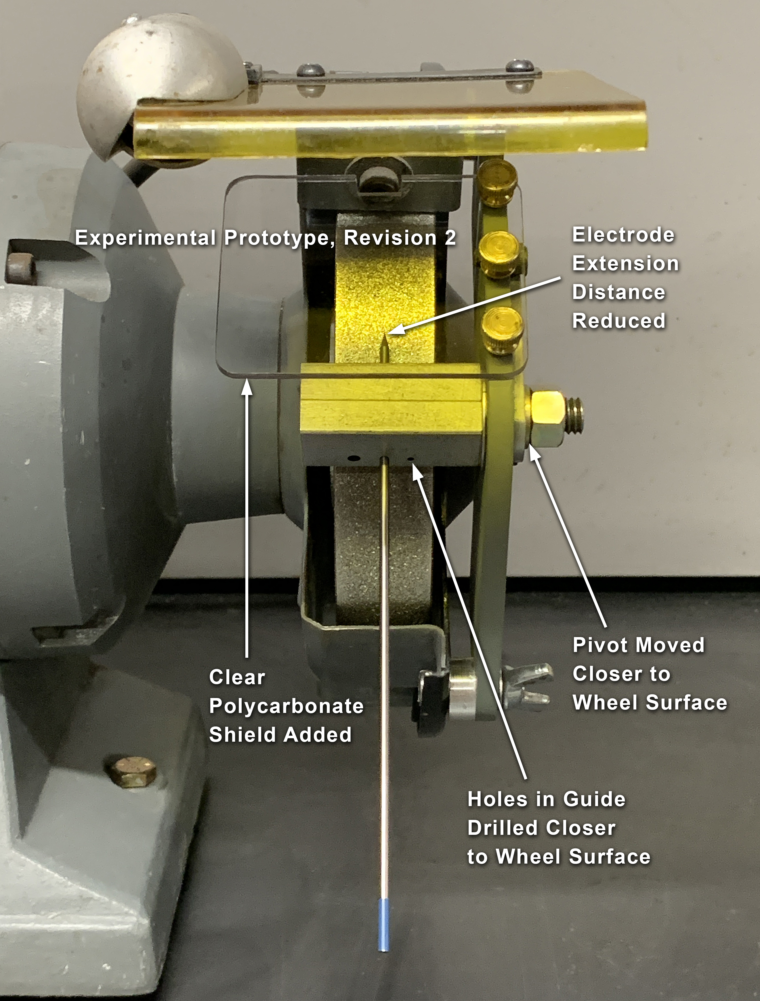
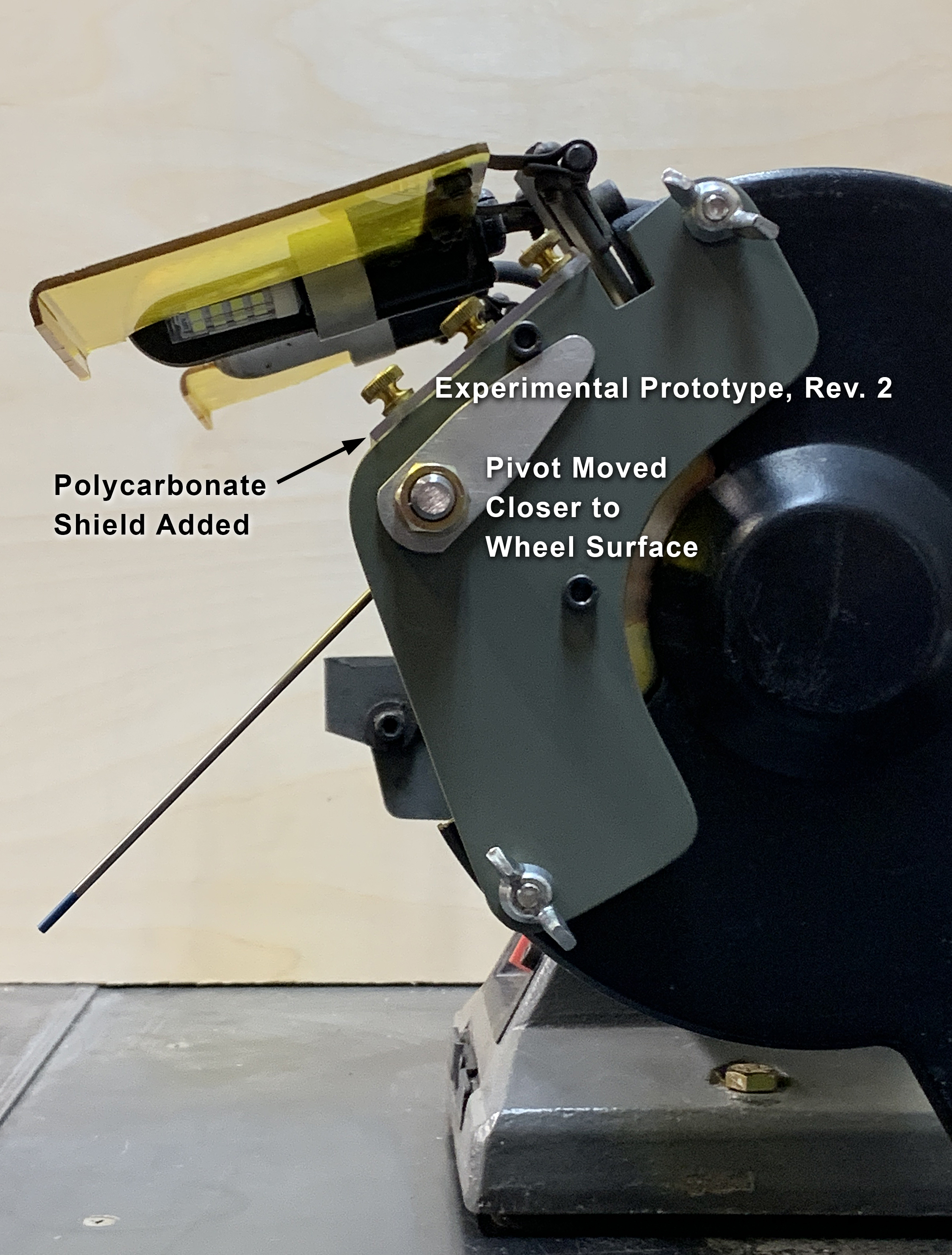
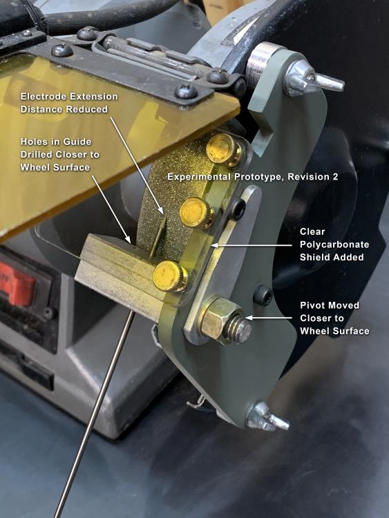
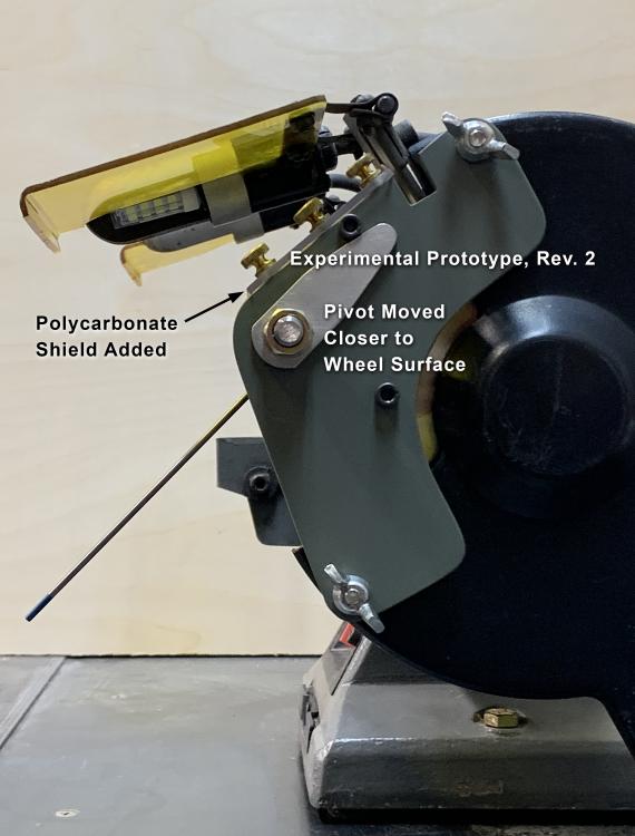
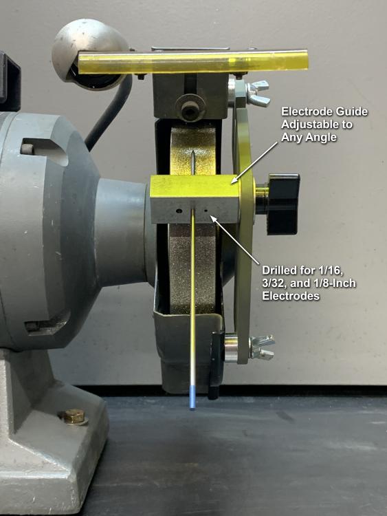
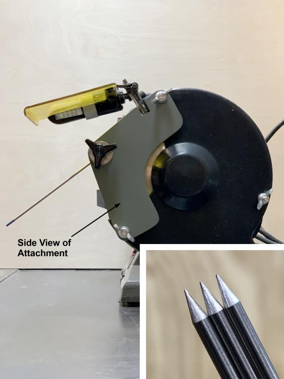
Updated material to "Experimental Jig for Sharpening Tungsten Electrodes” Revision 2. In this revision I moved the electrode guide pivot closer to the wheel and also drilled the guide holes closer to the wheel. These changes place the electrode closer to the wheel surface and reduce the distance that the electrode extends past the electrode guide (as shown below). One person contacted me with a similar suggestion. I think these changes could make grinding results more consistent. I do not know what effect these changes might have on the possibility of kickback or breakage. I haven't experienced any problems yet, but I haven't ground very many electrodes with the different versions of this device, and there is always a chance of electrode breakage or kickback. I would have to do a lot more testing before I would feel confident about the device's safety and effectiveness. I also installed a clear polycarbonate shield over the electrode grinding area (as shown below). I thought this might offer some additional protection in the event of damage occurring to the electrode. I attached the shield with thumbscrews for easy removal for cleaning or replacement. Even when using the bench grinder's original polycarbonate shield along with the new shield that I installed, I still wear eye protection when grinding electrodes (or anything else for that matter), as well as keeping myself clear of the end of the electrode when feeding it into the grinder. As stated before, this is an experimental prototype and a work in progress, so I do NOT recommend copying this design. More changes will probably be upcoming, if or when time permits me to do further experimenting and testing. Feel free to PM me or leave a comment. Disclaimer: The device described here is an experimental, prototype device. I do not warrant the safety, efficacy, or applicability of the device described here. Any use of this design or device is entirely at your own risk. Use all appropriate personal protective gear when using this or other tools. This post is not intended to be instructions for grinding tungsten electrodes. It is only a description of an experimental prototype device in its early development stages. Disclaimer: The device described here is an experimental, prototype device. I do not warrant the safety, efficacy, or applicability of the device described here. Any use of this design or device is entirely at your own risk. Use all appropriate personal protective gear when using this or other tools. Thanks for reading, and please check back for further updates. Please PM me if you have any questions or comments you'd like to discuss offline. Al (Steamboat)

-
“Updated material to Experimental Jig for Sharpening Tungsten Electrodes” Revision 1. I have made some changes to the original version of this device. As mentioned, this is an experimental prototype device. It is a work in progress and not in its final form, so at this point, I do not recommend building a copy of it. As I experiment with it and discover new problems or shortcomings, I will try to improve the device with safety, efficiency, and ease-of-use in mind. Please note that I am not a professional in any of the fields related to developing this device, and I am open to suggestions to improve my design. In this revision, I made the following changes: I replaced the knob used for tightening/locking the position of the electrode guide with a hex-head bolt that can be securely tightened with a wrench. Rationale: This will allow the electrode guide to be locked more tightly and securely in position and make it less likely to move while in use. I connected an arm to the electrode guide and added stops to limit the angular range of the electrode guide to PREVENT electrodes from being pointed downward in the direction of wheel rotation. This device is designed for grinding electrodes in the general orientation that I depicted in the photo in the original post and also below (i.e., against the rotation of the wheel). Rationale: Because this device employs an ELECTRODE GUIDE, if one were to grind an electrode with the tip pointing downward in the same direction of the wheel’s rotation, the wheel could “grab” the electrode and pull it down through the electrode guide, which could jam the electrode against the wheel, destroy the electrode, and possibly even send pieces of the electrode flying through the air, which could be dangerous. This modification is intended to prevent that situation. The electrode angle relative to the wheel is limited to the range shown in the photos below. This setup prevents the electrode from being pointed downward beyond the point where it is perpendicular to the surface of the wheel. In other words, it prevents the electrode from being pointed in the direction of wheel rotation. FYI, here is an informational (not sales) link to a Miller Welding document available at the time of this post, which includes some basic information on electrode preparation and grinding (see the bottom of page 8): https://www.millerwelds.com/-/media/miller-electric/files/pdf/resources/gtawbook.pdf Warning: It is very important to try to avoid kickback when grinding electrodes. Before grinding an electrode, I make sure the diamond wheel is running true and that the surface is smooth and free of any irregularities that might increase the chance of kickback. I feed the electrode through the electrode guide into the wheel carefully, rotating it against the wheel with light pressure, while keeping myself clear of the opposite end of the electrode. While I have not "yet" experienced any kickback when using this prototype device, to be on the safe side, one should always assume that it is a possibility, and of course one should always wear eye protection and view the grinding process through the safety shield on the bench grinder. I have only tried this device with a diamond wheel. I do not have any plans at this time to try it with other types of abrasive wheels, such as aluminum oxide, silicon carbide, etc., as there are too many variables to deal with, and I don't believe that other abrasive wheels would last as long as diamond wheels for grinding tungsten electrodes. Possible upcoming changes in future revisions: I might modify the shape of the electrode guide and install it even closer to the grinding wheel. I think that this might add more stability to the electrode during grinding, since less of the electrode would be protruding from the guide. I don't know if it would have any effect on reducing the chance of kickback. A scale could be etched on the mounting plate, and the arm could be used as a pointer to indicate favorite grinding angles, which could save adjustment time. Again, this prototype device is a work in progress and not in its final form. There may still be bugs to work out. I expect to be making a number of further changes and fixing issues as they come up. I am sharing the development process on the IFI forum because I am not a professional in any of the applicable technical areas, and I would like to get comments from forum members that could help me improve this device. Disclaimer: The device described here is an experimental, prototype device. I do not warrant the safety, efficacy, or applicability of the device described here. Any use of this design or device is entirely at your own risk. Use all appropriate personal protective gear when using this or other tools. This post is not intended to instruct the reader in how to grind tungsten electrodes. It is only the description of an experimental prototype device in its early development stages. Thanks for reading, and please check back for further updates. You are welcome to PM me if you have any questions or comments you'd like to discuss offline. Al (Steamboat)

-
Thanks. So far, it's working great, and I haven't messed up any electrodes (yet). I had about 40 electrodes that needed sharpening, which was a good excuse to make the jig. The diamond wheel cuts quite quickly, so a light touch is needed, but it's easy to get the hang of it. Al (Steamboat)
-
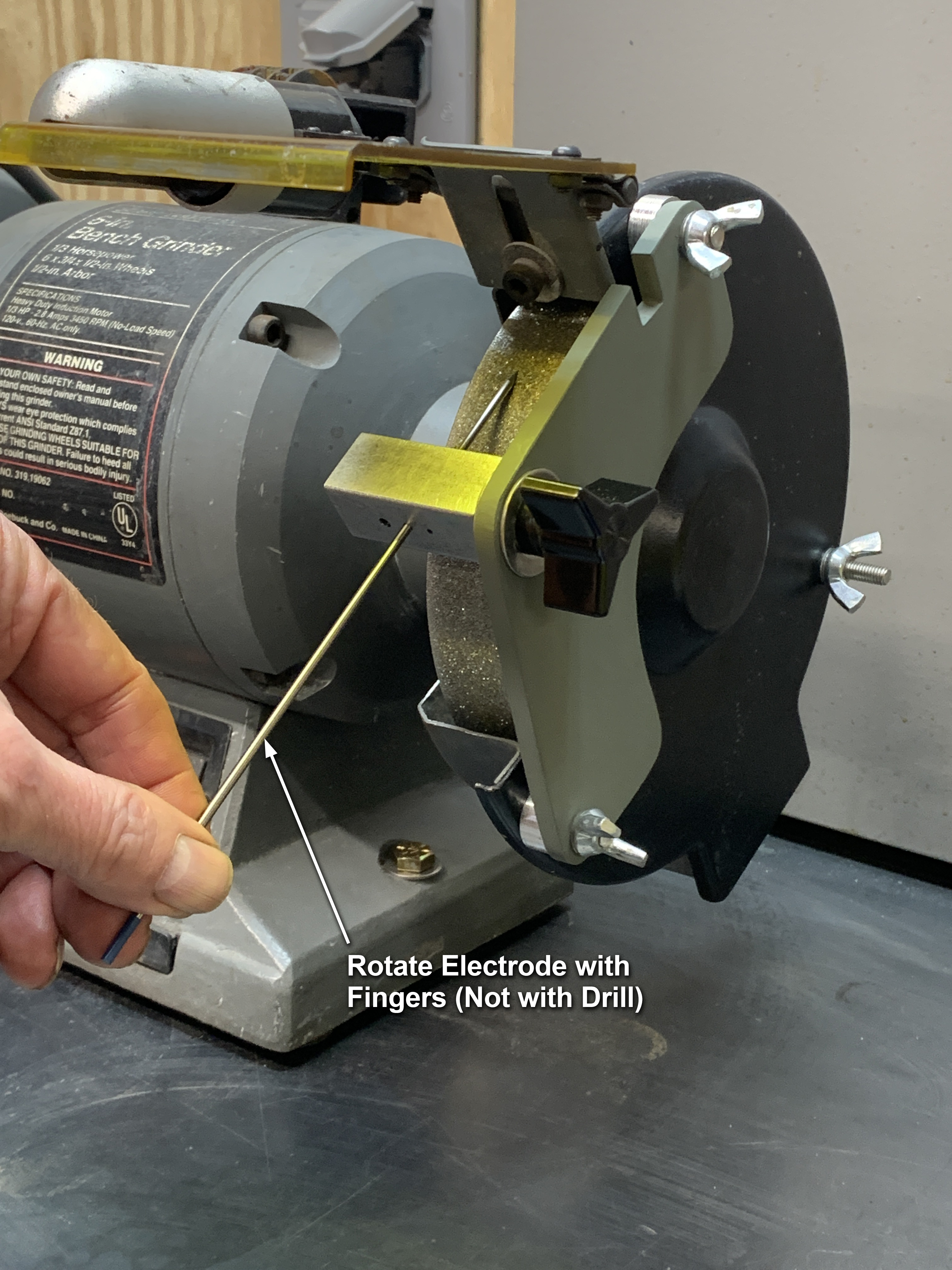
“Changes have been made to the design described in this post. Please refer to a later post below for an update.” I haven't posted here on IFI for quite some time, as I've been absolutely swamped with other projects and tasks like major home restoration work, property issues, a big archaeology excavation project, and other things that I won't bore everyone with. I'm finally getting back to the process of setting up a new workshop at home on a limited budget, and I'm making decent progress, although trying to fit all of my equipment into a relatively small space and still have enough room to work is pretty challenging. I decided to start posting a few of the things that I've been doing or making in the shop. I might also post this particular item on weldingweb.com. Yesterday I fabricated a bench grinder attachment/jig for sharpening tungsten electrodes for my TIG welder. Previously, I had been sharpening electrodes manually on a 12-inch disc sander, which worked OK, but this little jig helps me quickly produce nice consistent results. I had an old Craftsman bench grinder that was gathering dust, so I decided to dedicate one side of the grinder exclusively to sharpening electrodes, thus avoiding contaminating the tungsten with other materials. I installed a 6-inch diamond wheel (about 34 US dollars) on the grinder, using a bronze bushing to adapt the wheel's 1-inch bore to the 1/2-inch shaft. I cut the mounting plate out of 1/4-inch mild steel plate, and for the electrode guide, I drilled holes in a piece of 3/4" x 3/4" square bar stock for 1/16, 3/32, and 1/8-inch electrodes, which are about the only sizes that I use with my TIG welder, and drilled and tapped a hole for the tightening knob. With this jig I can set the electrode at any angle relative to the wheel to produce any angle of tapered point that I want. Also, the grinding marks produced by this setup are aligned WITH the electrode (and NOT spiraled or perpendicular to the electrode), which helps produce a steadier, more consistent arc. I doubt that I will ever wear out this diamond wheel by grinding electrodes, but if by some chance any tracks should become worn into the wheel's diamond surface, it's a simple matter to either add or subtract a washer to move the electrode guide a bit to the right or left over an unused portion of the surface. In hindsight, I think I would have gone with a somewhat finer grit (this wheel is 120 grit), but as long as I use a light touch when grinding, it quickly produces "relatively" smooth results, and since the grinding striations are oriented correctly (aligned with the electrode), I'm not overly concerned about getting it super smooth. When using this jig, I rotate the electrode ONLY with my fingers, rather than chucking the electrode in a drill, as I believe there is a danger of bending or breaking the electrode if any kind of powered drill is used to spin the electrode in the electrode guide. Note: I do NOT grind thoriated tungsten electrodes because I do not want to deal with the hazard of radioactive dust. I'm happy to stay with other types of tungsten (ceriated, lanthanated, E3, etc.) and avoid thoriated electrodes altogether. As usual, here's my disclaimer: The device described here is an experimental, prototype device. I do not warrant the safety, efficacy, or applicability of the device I have described here. Use this design or device entirely at your own risk. Use all appropriate personal protective gear when using this or other tools. Any comments or suggestions are appreciated. Cheers, Al (Steamboat) “Changes have been made to the design described in this post. Please refer to a later post below for an update.”

-
Thanks, W! Looks good, Timber Ridge! When you mount the vise on a base (or floor, perhaps?), just be careful when you tighten the bottom flange to whatever base you decide to use under it. If the flange is over-tightened against a surface that doesn't match the bottom flange surface perfectly, the cast iron could crack. Cheers, Al (Steamboat).