JHCC Posted August 21, 2019 Share Posted August 21, 2019 As noted in the "What did you do in the shop today?" thread, I've mounted a bigger motor on my horizontal bandsaw, the last one being terribly underpowered. Unfortunately, it goes the wrong way around, and I need to figure out how to reverse it, if possible. Here are some specs: the motor is a Marathon Electric model LQF 56C17G2007A W, 1HP, single phase, 115/230V. There is no "motor not reversible" warning or wiring diagram, nor is there the usual terminal cover ("peckerhead"). Instead, there is a box sticking off the side with a switch on its side and an ammeter and an hour counter on the top. Here's what's going on underneath the cover of that box: The incoming green wire is connected to bare copper ground. The incoming white wire is connected to two wires: one gray and one white The gray wire is connected to three wires from the motor: Black with white hash marks Brown Red The white wire connects to the hour counter and then (via a black wire) to the blue wire coming from the motor The incoming black wire connects to the switch, and then (via a red wire) to the blue wire coming from the motor. There are three wires coming from the motor that are not connected to the incoming wires: Black Yellow White Any thoughts? Quote Link to comment Share on other sites More sharing options...
Irondragon Forge ClayWorks Posted August 21, 2019 Share Posted August 21, 2019 Have you tried contacting Marathon Motors? They have a web site, just can't link it. They should be able to tell you if it's reversible. Quote Link to comment Share on other sites More sharing options...
JHCC Posted August 21, 2019 Author Share Posted August 21, 2019 Yes, and the friendly lady in technical support gave me the email for the engineering department. I emailed them and am awaiting an answer. Quote Link to comment Share on other sites More sharing options...
pnut Posted August 22, 2019 Share Posted August 22, 2019 Hmm. It's early and I haven't had enough coffee. Would mounting the motor facing the other way change the direction. In my groggy mind it seems like it would. Pnut Quote Link to comment Share on other sites More sharing options...
Dax Hewitt Posted August 22, 2019 Share Posted August 22, 2019 Mounting the other way was my first thought but having seen the photos it wouldn't be easy to do and probably get in the way. Single phase motors are a real sod, every manufacturer uses different colour coding and often wires them a different way. Single cap, dual cap, centrifugal switches. It's voodoo I tell you. I just checked my wiring diagrams but don't have anything for that manufacturer. Quote Link to comment Share on other sites More sharing options...
JHCC Posted August 22, 2019 Author Share Posted August 22, 2019 Mounting the other way is doable, but it puts the on/off switch on the far side of the machine. Possible, but a bit awkward. Quote Link to comment Share on other sites More sharing options...
Dasher Posted August 22, 2019 Share Posted August 22, 2019 As others have said, many AC single ph motors are not reversible, have you considered turning the motor around and driving the saw via a lay shaft? It will probably cost a few bucks for the added pulleys / bearings etc, but it is an option. Quote Link to comment Share on other sites More sharing options...
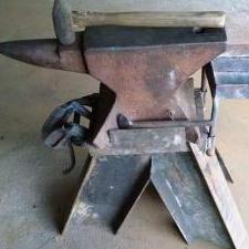
JHCC Posted August 22, 2019 Author Share Posted August 22, 2019 Turning the motor around would only require making and welding on a new mounting bracket. The only expense would maybe be a new v-belt, if I needed a different length. Current setup: Quote Link to comment Share on other sites More sharing options...
JHCC Posted August 22, 2019 Author Share Posted August 22, 2019 Update: the engineering department at Regal Beloit (current owners of Marathon Electric) emailed to say they couldn’t find that model number in their database. I’ve emailed them a photo of the nameplate. Quote Link to comment Share on other sites More sharing options...
Chris C Posted August 22, 2019 Share Posted August 22, 2019 I hate it when that happens. You call'em with THEIR model number and they claim they don't have a matching number in their data base. Been there-done that. It's infuriating, to say the least. Quote Link to comment Share on other sites More sharing options...
Buzzkill Posted August 22, 2019 Share Posted August 22, 2019 Given all that I'd probably choose to mount the motor the other way between the legs and install a new on/off switch where I found it convenient to operate. I might even consider removing the current box on the motor to remount in another location and just run some extra wire. Quote Link to comment Share on other sites More sharing options...
JHCC Posted August 22, 2019 Author Share Posted August 22, 2019 Well, here’s a test mounting with the motor the other way around. Seems to work pretty well (especially with the higher horsepower), although I will have to enlarge the base slightly to make it a bit less tippy. Frankly, I was thinking of doing that anyway, because the bed rail casters really aren’t up to the job. So, if the manufacturer comes through with information about reversing the motor, I can always move the motor back to the other mounting. Otherwise, I’ll turn the switch box to make it more accessible. Quote Link to comment Share on other sites More sharing options...
Stash Posted August 22, 2019 Share Posted August 22, 2019 Could you get a slightly longer belt and put a single twist in it? Then shim the motor slightly out of plane so the belt won't rub itself. Steve Quote Link to comment Share on other sites More sharing options...
JHCC Posted August 23, 2019 Author Share Posted August 23, 2019 This seems to work pretty well. The drive pulley is too small for me to put it very much out of plane with the pulley on the saw, but I have an idea for minimizing rub. More on that later. The weight is much better distributed, and the switch is now in the perfect position relative to the operator. I might make a guard to protect the switch box and motor from falling offcuts, but only if that becomes a significant problem. Quote Link to comment Share on other sites More sharing options...
Chris C Posted August 24, 2019 Share Posted August 24, 2019 Uh, I'd be more worried about "metal saw dust" than drop offs. Quote Link to comment Share on other sites More sharing options...
JHCC Posted August 24, 2019 Author Share Posted August 24, 2019 The switch box isn’t in the path of the shavings, and the motor is TEFC. Nonetheless, I have a cunning plan! More later. Quote Link to comment Share on other sites More sharing options...
Chris C Posted August 24, 2019 Share Posted August 24, 2019 Okay. Just bolt a cookie sheet onto the saw underneath the drop off area. (come on, work with me here!) Quote Link to comment Share on other sites More sharing options...
JHCC Posted August 24, 2019 Author Share Posted August 24, 2019 Update: made a guide from some bits of pipe to keep the belt from rubbing on itself at the crossover: With the motor mount welded down, we’re basically good to go. Thanks for the suggestions and input. Quote Link to comment Share on other sites More sharing options...
Chris C Posted August 24, 2019 Share Posted August 24, 2019 Whatever works. Hope the friction doesn't heat that belt up too much. Quote Link to comment Share on other sites More sharing options...
JHCC Posted August 24, 2019 Author Share Posted August 24, 2019 So far, so good. As a hobbyist, I am not using it so much that heat buildup would be a major problem. Quote Link to comment Share on other sites More sharing options...
Chris C Posted August 24, 2019 Share Posted August 24, 2019 Gotchya! Quote Link to comment Share on other sites More sharing options...
pnut Posted August 25, 2019 Share Posted August 25, 2019 You could use a little automotive belt dressing if it does heat up, that may help some. Pnut Quote Link to comment Share on other sites More sharing options...
Mr Moose Posted August 26, 2019 Share Posted August 26, 2019 That will make the belt grab a hold of the guides. Quote Link to comment Share on other sites More sharing options...
rockstar.esq Posted August 28, 2019 Share Posted August 28, 2019 JHCC Could you identify the wires coming out of the motor? It's a little hard to see in the pictures and your post doesn't explicitly say what each motor lead is connected to beyond that they're not connected to the incoming wires. Also, it's pretty important to know what the nameplate ratings are for voltage, current, frequency, and RPM's. The color code is manufacturer, and sometimes technician specific. Assuming that you're dealing with a single speed motor, chances are good that you've got a split phase motor with separate start and run windings. Since it doesn't have any capacitors, the start windings should have significantly higher resistance than the run windings. If you or someone you know has the ability to safely take resistance measurements, you might be able to determine which wires go to the start windings. Unless I misread your post, it sounds like you have six wires coming out of the motor. If so, it's possible that two are for start windings , two are for run windings, and two are for the centrifugal switch. Two of the pairs should have distinctly different resistance measurements, while the third pair should read zero, or near-zero resistance. If that's the case, you could swap the polarity of the start windings in the circuit, which will reverse the motor's direction of rotation. While all of that might have sounded like gibberish, it's actually easier than it sounds. If the ohm meter reads infinite resistance on two given leads, it's telling you that they are not a pair. If the ohm meter reads zero resistance on two given leads, it's telling you that the leads are connected, which suggests they're tied to the switch which is normally closed. If the meter reads some distinct resistance, on a pair, it's telling you that those leads connect to a winding. Again, please be safe. Also, be advised that some of the cheaper multi-meters have ohm scales that only read in the kilohm (1,000 ohms) range. You'll need better granularity than that to get useful information. I hope that helps. Quote Link to comment Share on other sites More sharing options...
JHCC Posted August 28, 2019 Author Share Posted August 28, 2019 In the end, twisting the belt gave me the effect I needed, without having to mess around with the wiring or trying to get inside the motor housing. I appreciate the info, though, and might give it a shot one of these long winter evenings. Quote Link to comment Share on other sites More sharing options...
Recommended Posts
Join the conversation
You can post now and register later. If you have an account, sign in now to post with your account.