Daedelus
Members
-
Joined
-
Last visited
-
-
Thanks for the warning Mikey. Even though the regulator is newly bought from the propane supplier, a regulator fires sounds bad. (Edit: I have looked up the product/order again, and the product information is as follows: Adjustable pressure for all applications with high pressure. High pressure regulator, 0 to 3 bar Throughput 8kg-12kg/hour In 1/4 innerthread Out: 1/4 innerthread Approved for Hot Air Canons and gas burners to 55 kW. Reference: https://multiflame.nl/product/hogedruk-gasdrukregelaar-0-3-bar/ model: NC2005L) Previously I used a 0.6 mm mig tip which lead to a red hot mixing tube. After this I switched to the 1.0 mm mig tip I had. What size would be recommended, back to the 0.6mm or try a 0.8mm?
-
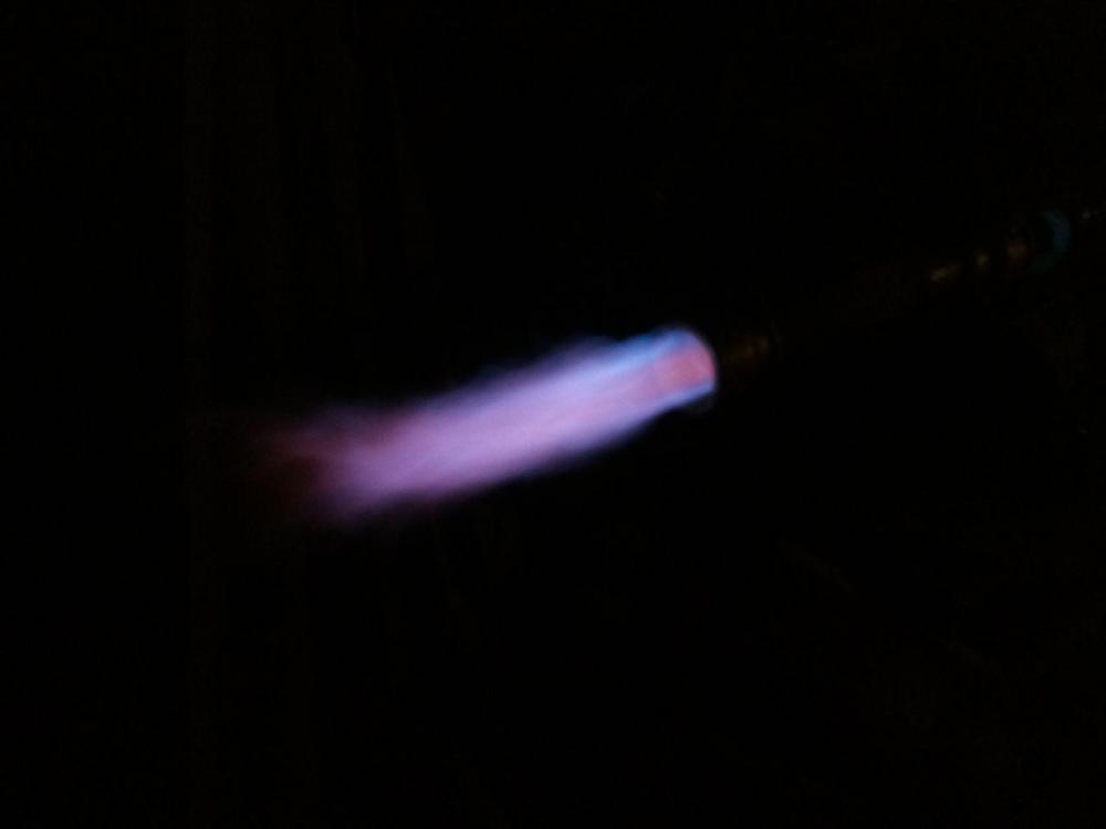
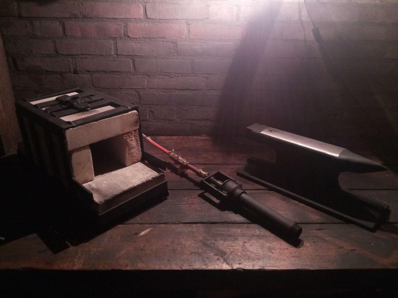
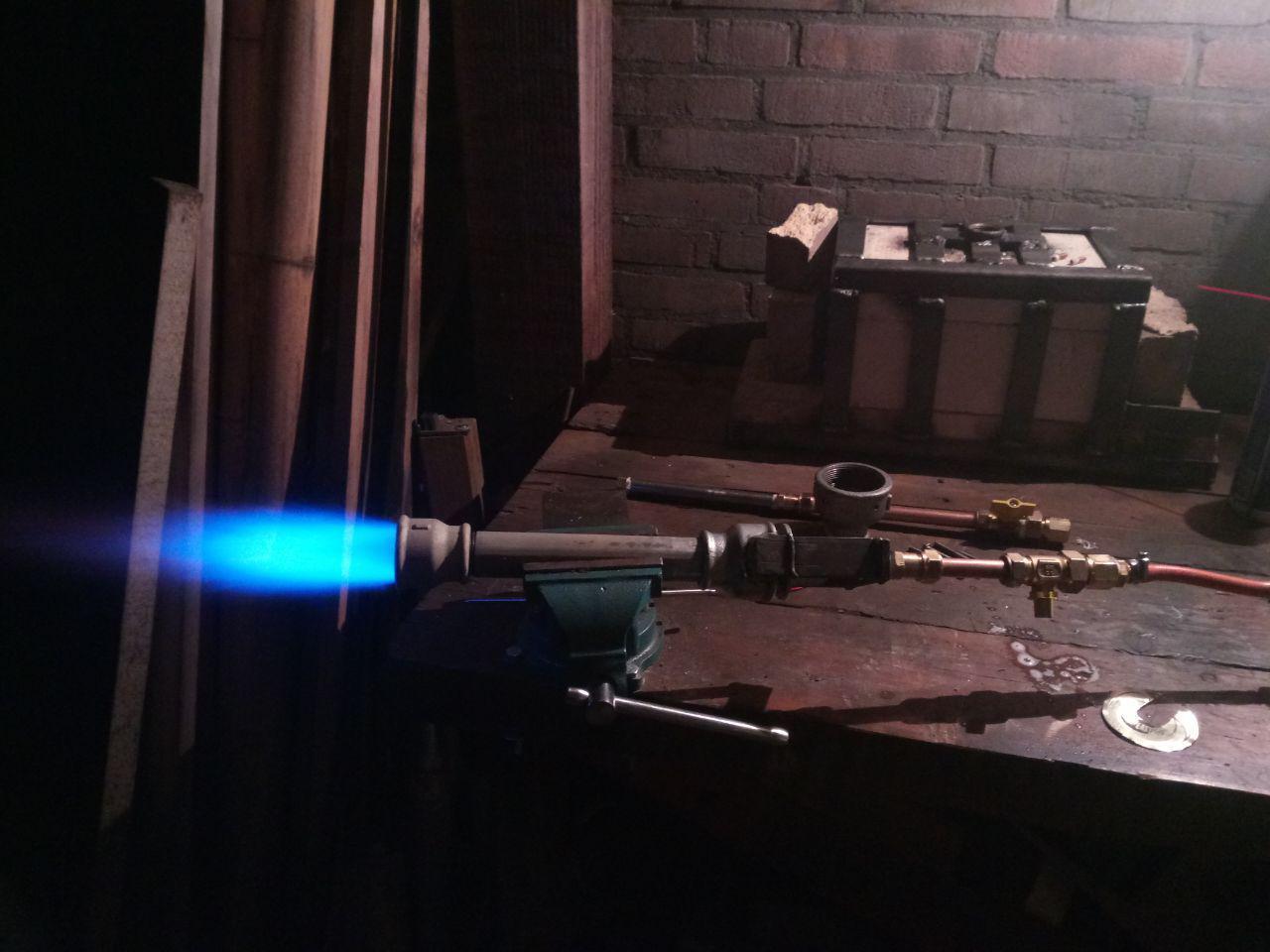
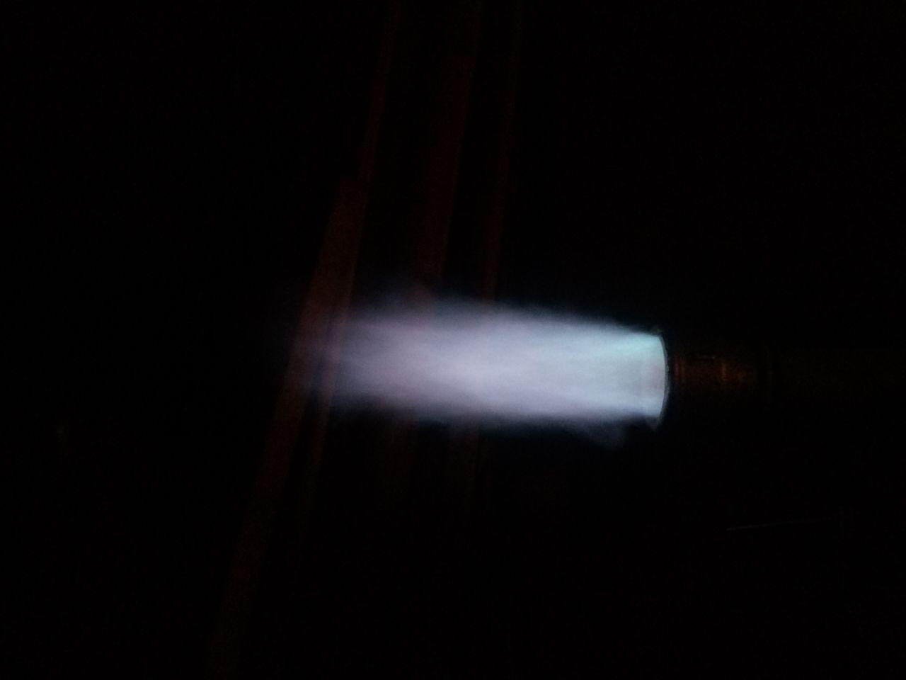
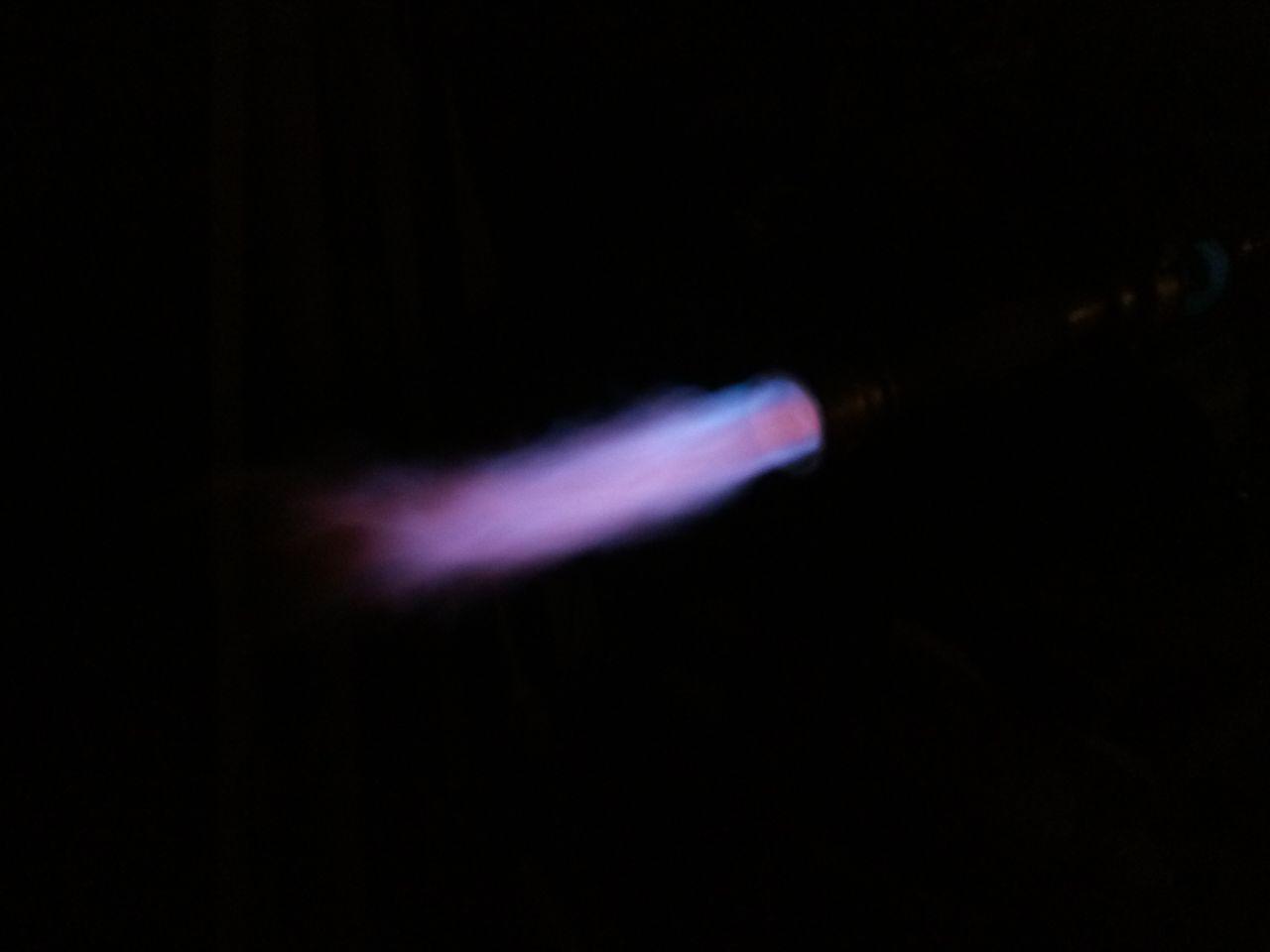
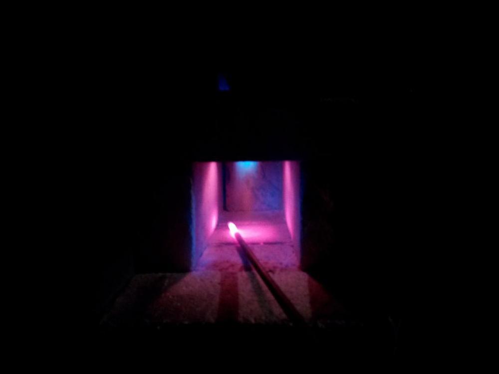
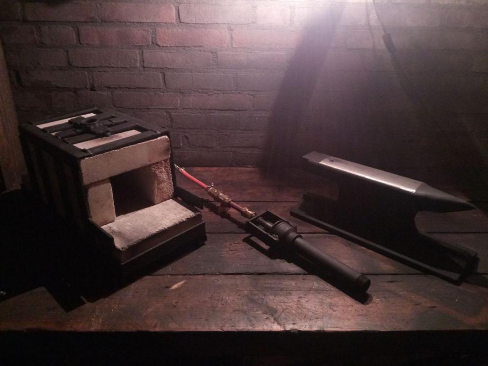
Hey Guys, Had a nice day off today and made myself a cart for the forge (and other future forges). There are a few updates that needs to be taken care of, such as the gas-hose extender and the airtight-top-seal as mentioned before. However this thread is for the burner, not for the forge! I have the propane pressure set to 0,5 bar on the tank, and have only changed the air-adjuster on the burner intake. I did not let the forge heat up before, so I would have the darkest background to make these shots. So this is what the burn looks like, with the new tank and adjuster: Small air opening: Medium air opening: Big air opening: Once I reduce the air opening, I can get a nice blue dragon's breath, however it is quite large. I suspect I need to adjust the pressure a little lower. Unfortunately I don't have a proper shot of this.


-
Agreed! The new regulator is in place and gave it a test burn yesterday. It's much easier to regulate and 0-3 instead of starting at 1 bar. I noticed it will take some getting used to, as well as finding the nice burn settings. During the daytime-test it was incredibly difficult to see the flame, and could only hear it. Will post results when I have some pictures.
-
I'd like to thank you for your patience, and hopefully you can rejoin this wonderful adventure into gaining precious skills. Good News! In the meantime quite a few things happened, I finally emptied my propane tank after the crappy weather went away (seeing as I work outside). I have returned my return&trade-tank and actually bought one, since I have caught bug and wish to proceed while minding cost a bit. This one is mine for the next 10 years, didn't cost anything compared to the loan-tank I had and now only have to pay per refill / what I use. Not only that, but I've also started a new job and was preparing my wedding (only one more month to go!), so you can understand it took a while before I could reply. Now, back to the burner: With the previous tank, I couldn't open my valve all the way and produce a clean air-flow, since I couldn't open the pressure regulator on the tank. Having this new tank means I can finally use my new pressure regulator. As advised by Mikey, it's a good idea to add a needle valve. I do not have my needle valve just yet, but it's in the works.
-
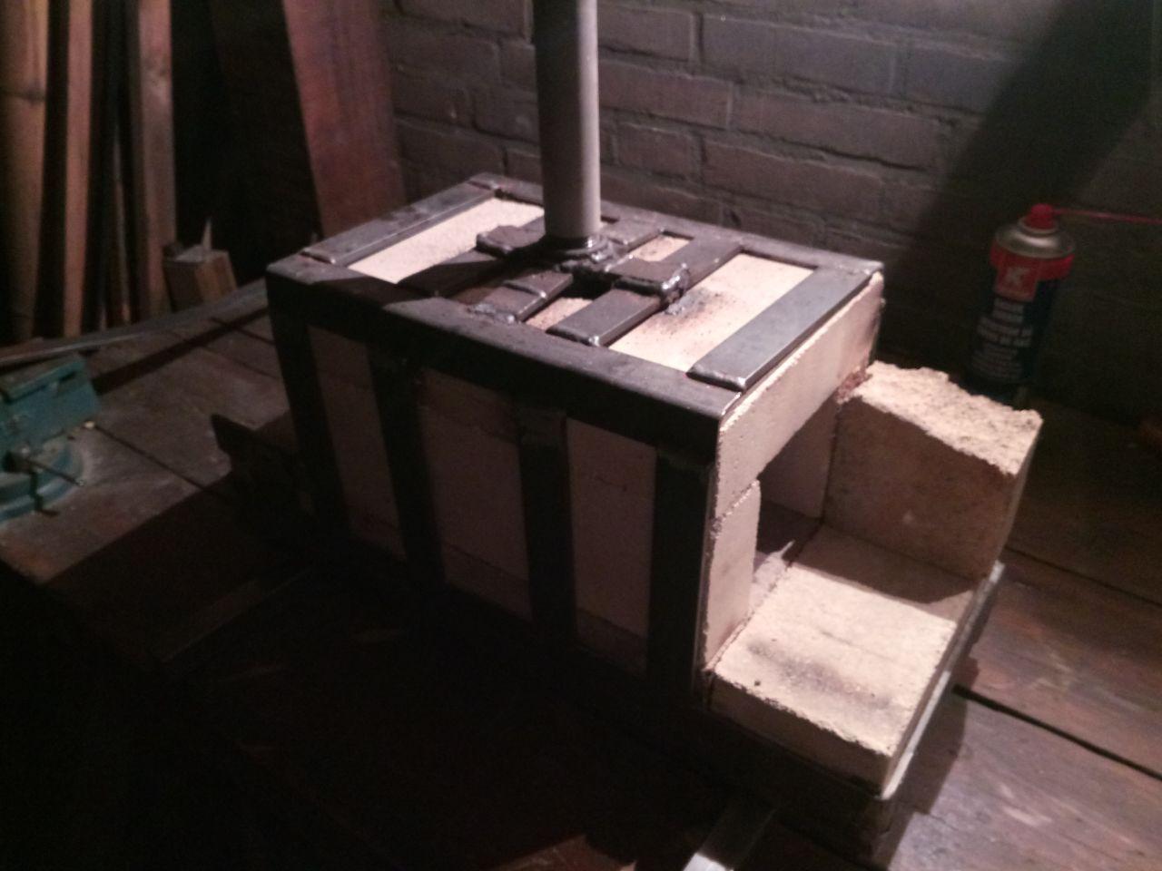
(Removed rest to contain the quote) - Thank you for the clarification! I thought Mikey meant a part of the burner itself, so didn't check the Forges 101 for this term yet. I could find car exhaust manifolds using google, so was a bit confused. I had seen caps with holes in front of the burner a few times before as well and is why I included a picture. I had the size of the forge mocked up so I can put bricks in between the sidewalls, all the way through. The way you mentioned is exactly what the first (and last) brick are included in the frame for, as shown below. I can easily lay a brick on it's flat and have a small gap, or place a smaller brick with an air opening on both sides and move it a bit. This is also what the 2 small ledges on the front are for, so I don't accidentally knock "the baffle wall" off if I need to shove them open. The burner was my main priority for this thread, so I will try to get this post back to that for the time being. When I can finally use the correct tank, tankregulator and have a proper way of tuning the burner with the mentioned needle valve, I want to look forward to building or upgrading this to a proper forge. Of course I will be reading up the Forges 101 before that (and keep Plistex in mind as well). Thank you all for your insight and time so far, I really appreciate it! (Note: This forge frame was never meant as a definitive forge, I had some time to kill and wanted to practice welding a bit so I could test my burner safely and in the right size environment I want to use. Also I wanted to be able to move the 'mock up forge' in and out of the way quick and easy, without the bricks having to cool down afterwards if it started to rain. This way I can move it to the forge-location before I want use it and store it immediately afterwards to keep it dry (bottom brackets so far stayed touchable by hand). So in a way this was a concept for my next forge . When I completed my railroad-anvil I wanted to protect it against rust and sprayed all the parts with some black heat resistant paint.)

-
I think this could be yes, if you take another look at the picture with the 0.5 burner, you can see just how merely the valve is opened ( - is open, | is closed, compared to the gasline). I will be putting a needle valve in between the burner and the ball valve then! I was in the under the impression that you regulate pressure (and flow) at the tank. I had a few improvements in mind: - I was also thinking of putting some refractory on top, to close the opening between the flare and brick off, good to know how I can glue that center brick back together as well. - I was thinking of putting in a 90 degree bend in a new longer copper tube, so the ball valve is not immediately above the forge. For now I'm not so worried about wear and tear on the bricks, but the openings between the bricks (hence the metal frame, which works quite well), saving fuel and working more efficiently is always a plus! I had not heard of Plistex before, so I will look this up. I had the idea to upgrade the forge with insulating blankets after a few successful forging sessions and perhaps redesign the forge altogether . So I will be aiming for the greatest need at present, but I'm not sure I know what you mean by a "baffle wall", should I think of something like this mounted in front of the exhaustflare? If this is case, how would this work, like a stove burner cap dispersing the heat to a greater area?
-
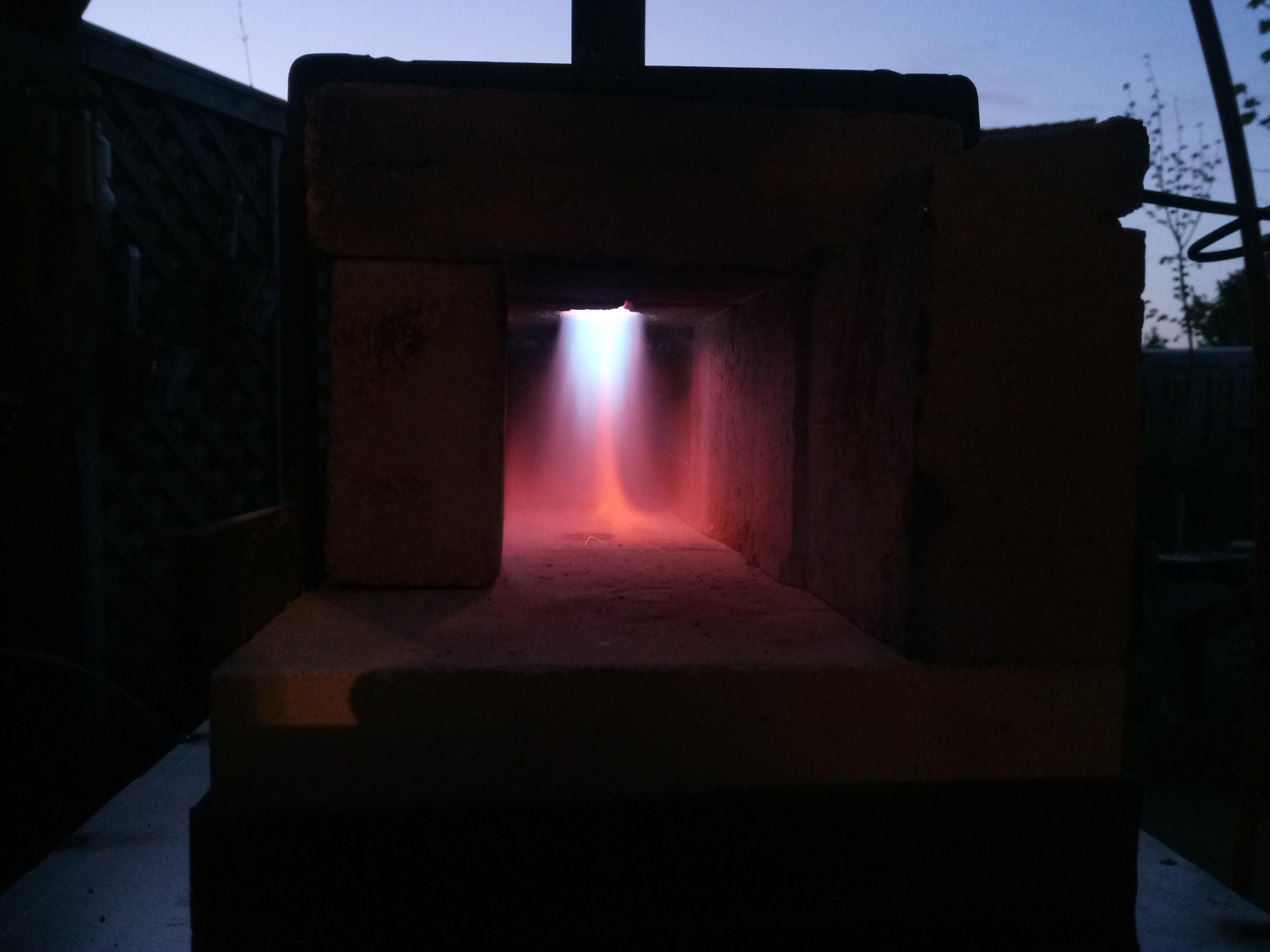
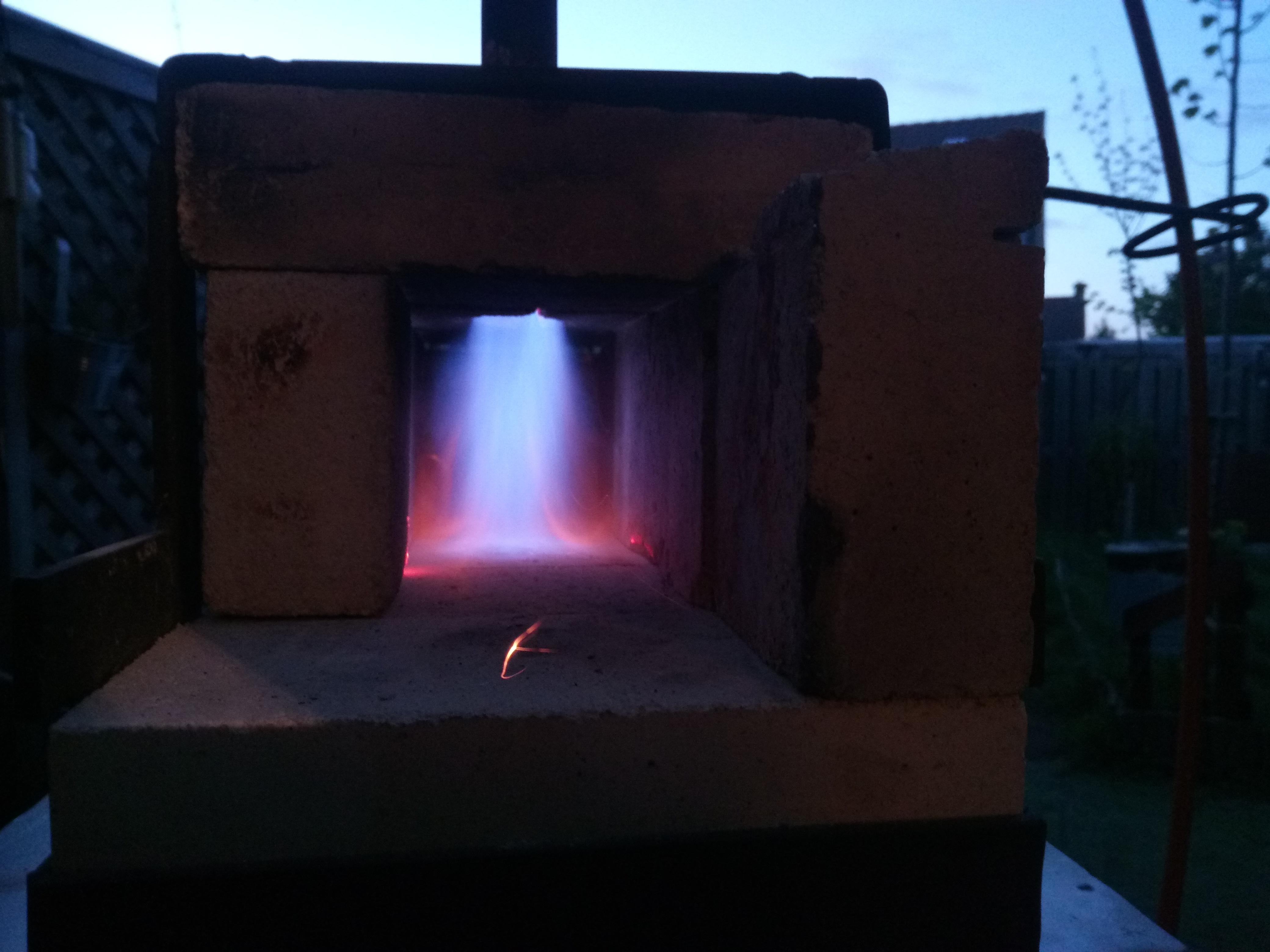
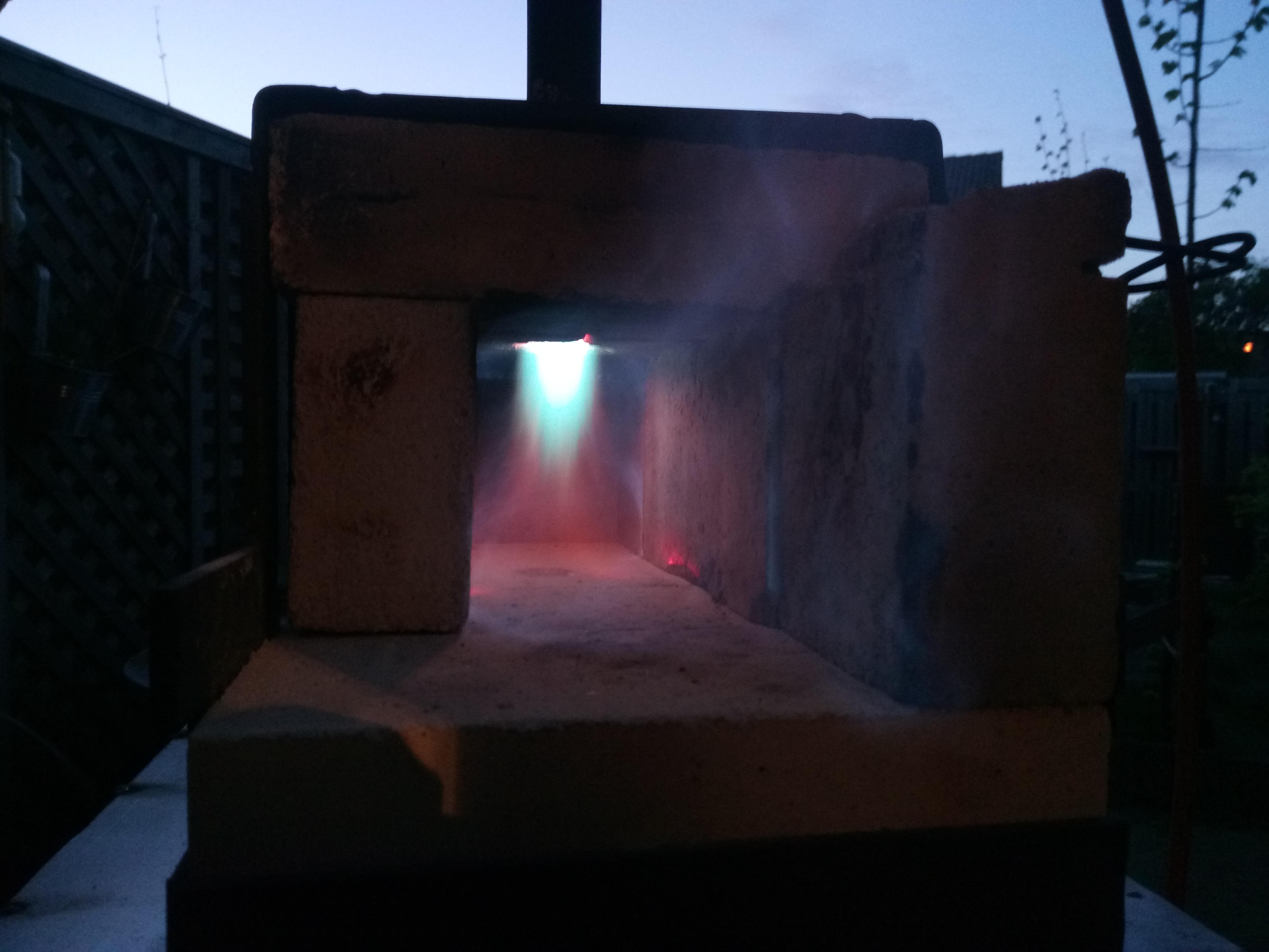
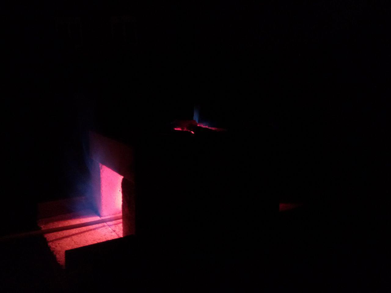
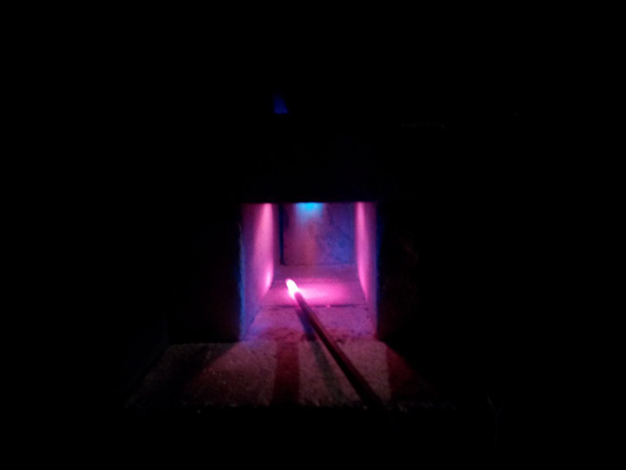
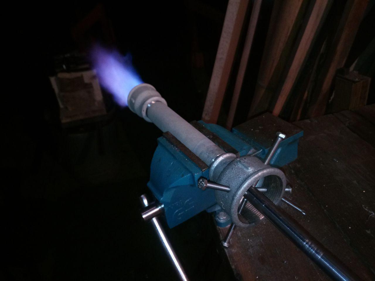
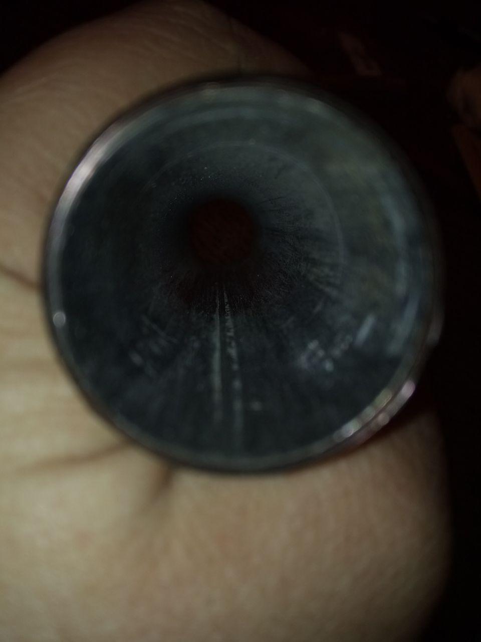
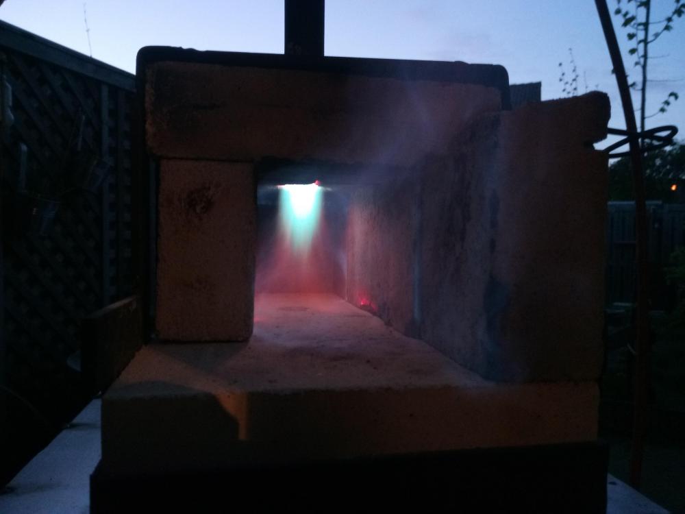
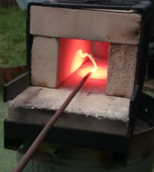
Mickey thanks for your time and insight! Unfortunately I haven't had the time to get back to the forge yet, due to having to wait out the bad weather (outside forge). I am now running with a 1.0 mm opening, what would be the better size, even larger? In these pictures, I have been taming the flame a lot, at two different points. With the current pressure reducer on the tank it's always on 1 bar minimum, this means opening the ballvalve ever so slightly and not being able to set pressure correctly and comfortable (I need/want to empty this tank first). In the third photo (with the brick) I was using a 0.6 mm migtip gasjet, 1 inch inside diameter (but only 15 cm long) and could remove the flare and brick as well to achieve the same flame. Unfortunately I don't remember what pressure this was on, but could have been up to 1.5 bar. The last time I had it burning I tuned the pressures inside the forge, in the following picture I had the lowest pressure I could get to (at this point in time) while still having a little dragon's breath coming out the front. I started with quite a lot of daylight and during forging had been heating the forge for quite a while. I was very happy only the tip got red (like the inside). There is a small issue visible in the dark picture as well and that needs to be taken care of. There is an opening in the top; due to the middle brick splitting after removing it from the forge a couple of times, so it's not sealing correctly. In the below pictures I can see a lot of light and colors has been changed by my phones camera, unfortunately.

-
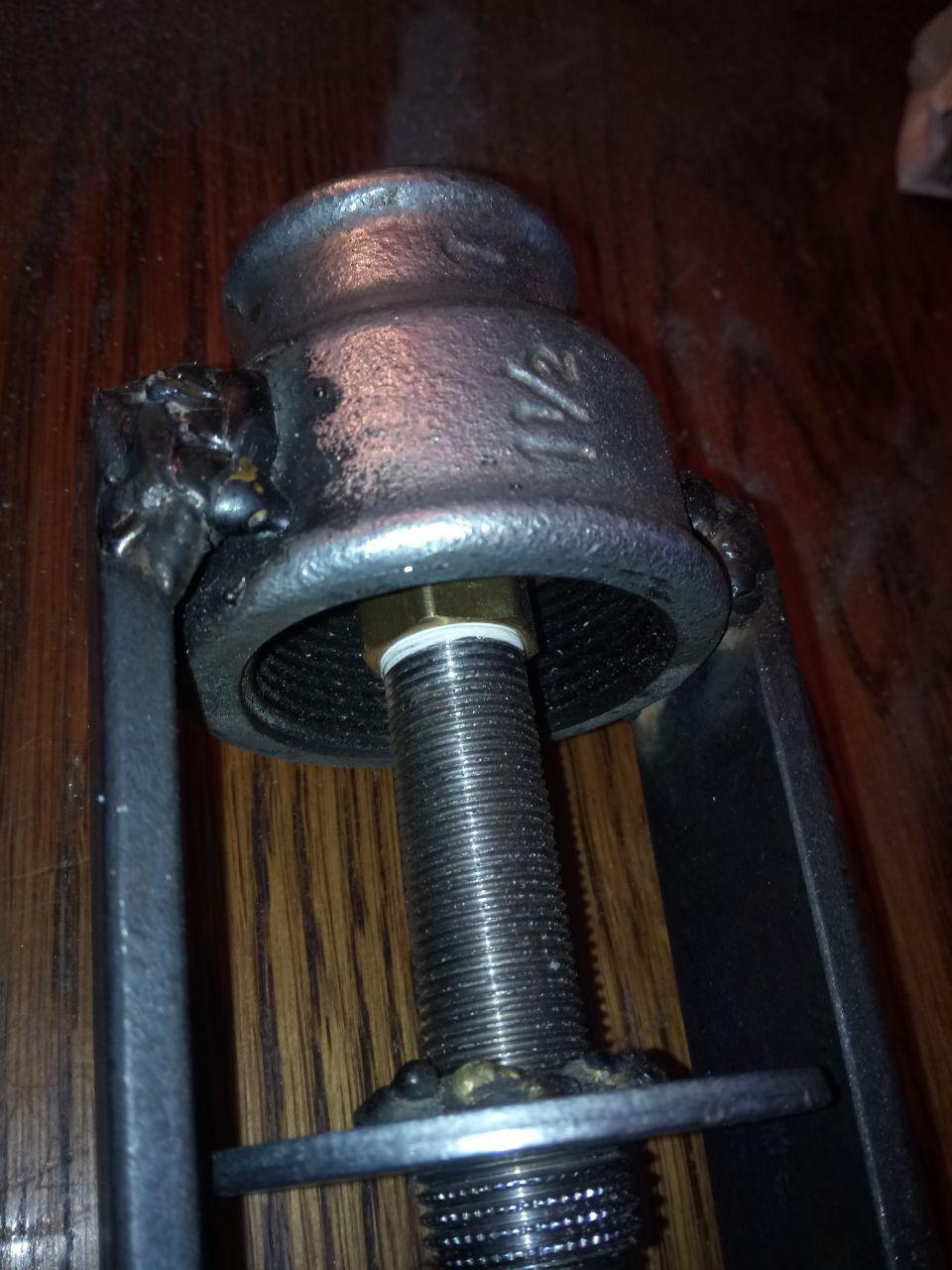
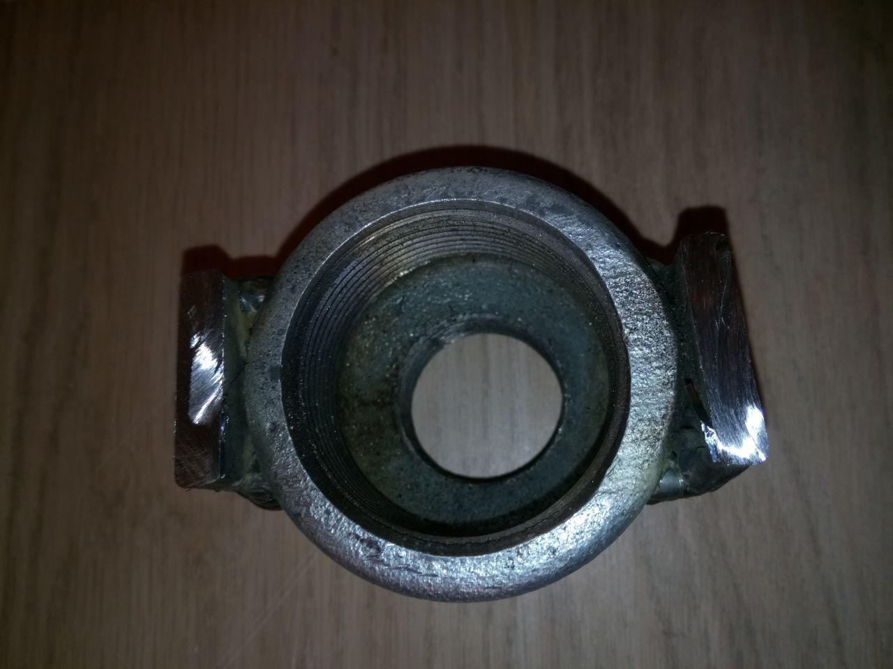
Thank you ForgeMonkey. I have spoken with a few of the physical shops around me (Zuid Limburg) and figured out that most of the stores don't have these anymore due to moving to a different plumbing system, being plastic(s). I started with parts from the hardware store Hornbach (3/8 stuff, pipe pieces, fittings), this is why it was the smallest I could easily go for at the time. Unfortunately they didn't have the rest of the burner-plumbing (intake, mixing tube, flare) and had to order this (I did this from the website St Middelkoop, they have quite a lot of parts). To create the air intake adjuster, I used a size 22 chassis-ring and welded a threaded 3/8 to 1/2 fitting trough it. For the hollow threaded pipe I used 16mm tube, which I threaded to 3/8th myself (toolset from HBM Machines, others were waaaay to expensive). I am a Dutch native and recognize the terminology differences, if you have any sites other than I mentioned I'd be happy to receive your DM. Thank you! Any ideas what could be done to get it even better?
-
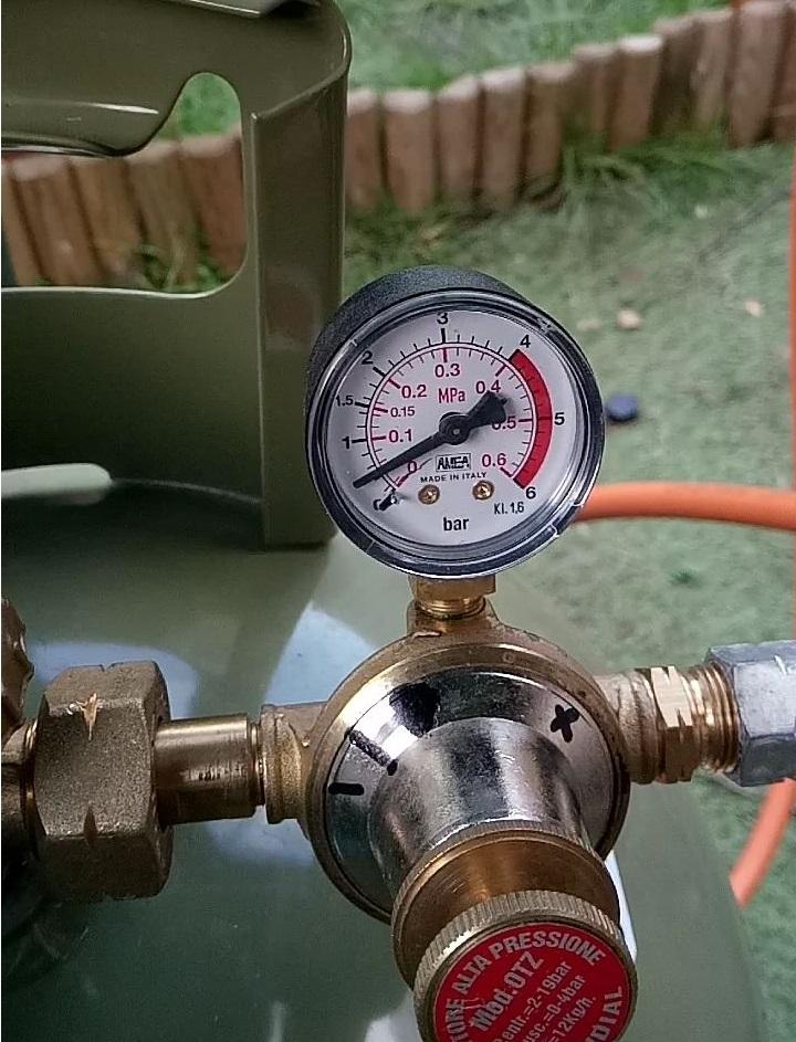
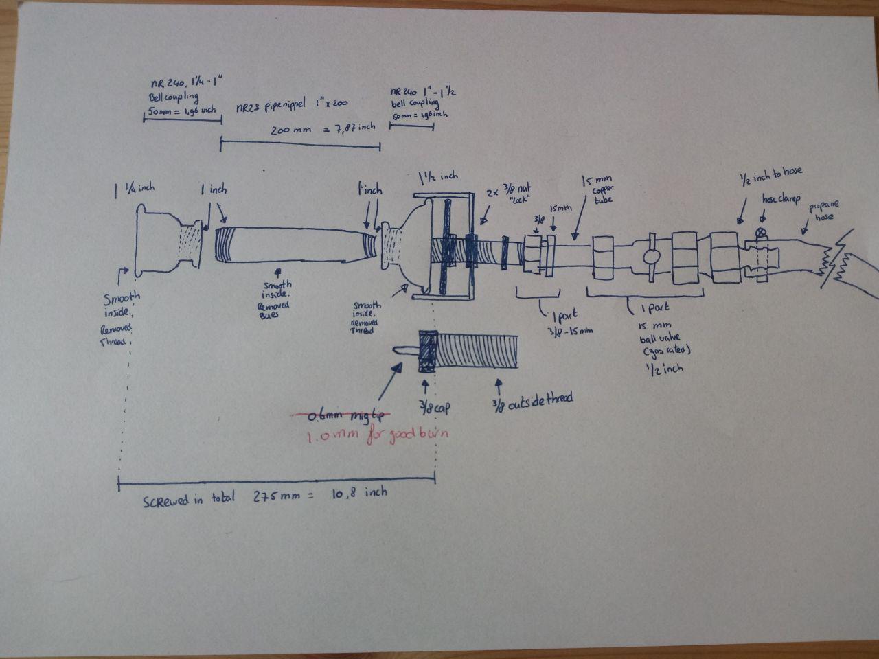
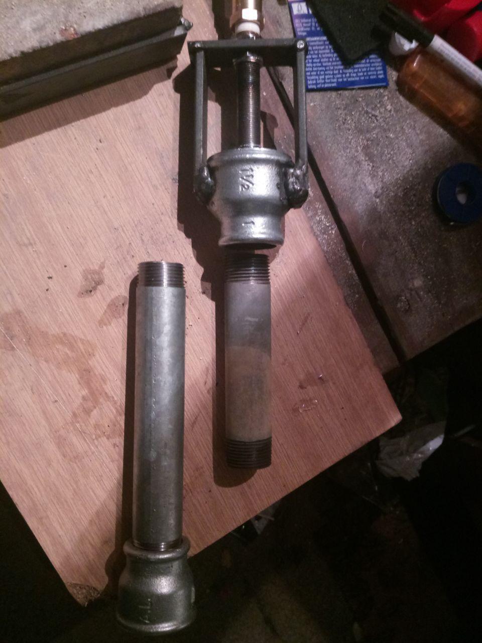
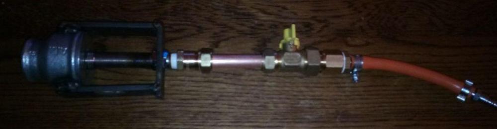
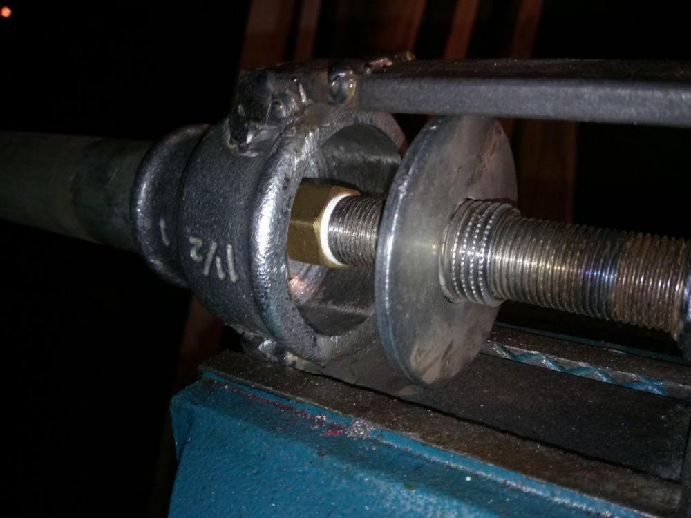
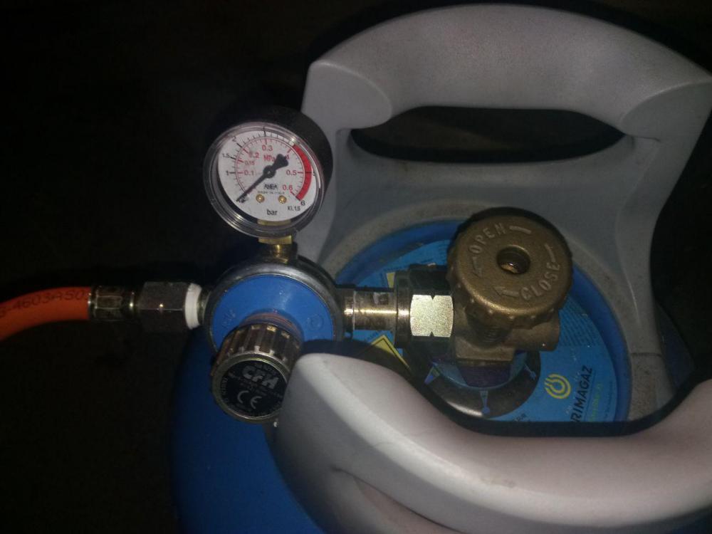
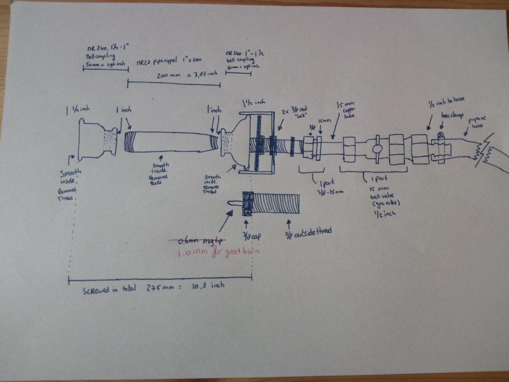
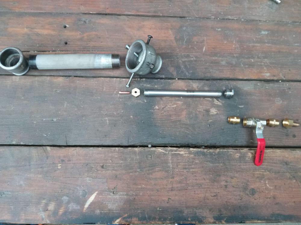
Hey Guys, I'm quite new here and wanted to share my DIY burner design (input is always welcome) and want to thank you all for the information you have collected and shared here. I started out with a wrong setup (using incorrect information) with a threaded air close off system, and have made my way to quite the comfortable burner. It's not the cleanest, looking at the welds, this will be a lot nicer when I get to make a second burner. I have documented lessons learning making this in a different post "Detailed learning curve and troubleshooting with my first DIY burner" Burner version 0.5 Inlet parts: Burn test after troubleshooting, the fluid is from testing for leaks. Also including the schematics with dimensions: For the eagle-eyed members, the inline ballvalve is hardly open, this is due to having the wrong pressure reducer on the tank (1-4 bar) and wrong tank, and will be taken care of. As you can see below, when the reducer is in the least open position, the knob and gauge actually press against the handle. I have tried looking for an extension, but couldn't find one. After this tank is emptied I will get a better tank and mount my correct pressure reducer (0-3 bar, which doesn't fit this tank at all).

-
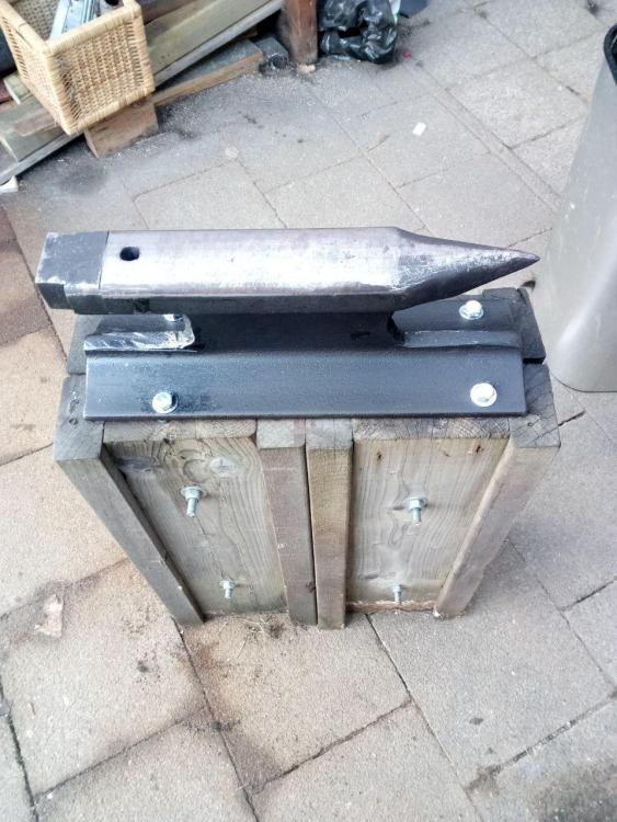
Kudos, very nice anvils can be seen in here. For me this isn't possible just yet, but have made my own starter anvil from a piece of railroad track. Hopefully it's okay to post this here too. First picture is a collection of my diy starterset, clean and painted, second is mounted on the stand and trying a few starter projects.


-
Made my first forge, burner, anvil and stand myself. Made the anvilstand using a piece of railroad track and two different sizes of wood. Completely threaded/bolted together (left to right is bolted as well, but not seen on picture). Glued and bolted the anvil to the stand.
-
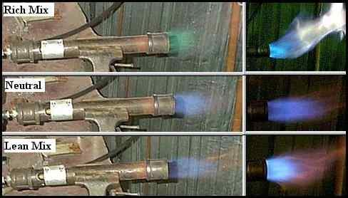
Now above I mentioned I thought it was a turbulant flame. I found some research and a high speed recording of this as well. Source: https://www.youtube.com/watch?v=Se5AjAxExog , FireScienceTools.com I also found a good representation of neutral flame and mix comparisons: Source: https://ronreil.abana.org/minifor1.shtml , Ron Reil And I found some comments here on I Forge Iron, two of which pointed me in the even better direction. At first I thought it was pressure related, due to having the wrong regulator. However one the comments mentioned everything was scaled, apart from the mig-tip / orifice. And this should have been enlarged exchanged as well. So: Burner Version 0.5 After a test run with a bigger mig-tip, I have achieved a flame with which I felt comfortable. Back to the old intake and it was still working fine. This is now my current set up, but with a proper pritchel hole: I will have a look back to see if I can find the original comments, to give credit where credit is due. But thank you all for sharing your knowledge. I hope this post will help people out, as much as you did for me.


-
I measured everything, drew up a new diagram of the current dimensions and wanted to ask my question on the forum, but felt a bit ashamed for changing the original design and not reading up even more. I did some more reading and found out that the intake had a relative dimension to the tube diameter as well. So ordered a bigger one. Burner version 0.4 For this bigger intake I took back to the original design to mount and align the mig-tip, so I had the option to change it on all axis and felt less ashamed to share my work. I used some of the parts of the current burner, with the (wrong) valve as a mock up and test. As you can see below this gave me a lot more blue flames instead of red blasting trough. Due to the original mounting of the mig-tip and intake, I was able to move the tip around: - Misalign it so it's offcenter - move further in or outwards The above was the most center I could get it, and as you can hear it's stil making the airsucking sound. I have added two videos, the first to show the difference in aligning and the second where alignment and pressure was the best I could get it at. Even though the flame is currently blue, it is nowhere near the performance it could and should be. Also I still couldn't get rid of the air-sucking intake sound. So, I took up some more research. - Continued on next post -


-
On of the things I learned is never to change more than 1 item. Otherwise you can get different results and don't know what caused it. Burner version 0.3 Using the list I started with extending the tube, this was the easiest to do. From the top of my head the length of the tube should be about 8 tot 9 times the diameter of the mixing tube. Using a 1 inch inside diameter meant I needed 9 inch tube. However in the Netherlands we don't use inches for length, which meant a length of 20.32 to 22,86 cm. The only pipe I could find was 20 cm's, so it had to do. This gave me a slighly better result. However on close inspection I could see the flame rolling and being distorted. Sorry for the vertical filming, but this was a perfect example which I couldn't get a proper picture of. Also note the sound, this is a softer air sucking sound. As you can see inside the flame tube, the base of the flame is rolling around, generating a distorted flame. This meant the next item on the list, my parts needed to be smoothed, since this is where the air gets the spiraling action from. I wasn't too happy about this since this meant cutting the supports, which is a good example of what could have been avoided had I done my research. 1. Deburred the tube (bottom) 2. Smoothed intake and flare 3. Results of smoothing As you can see the flame is a lot more stabilized, but if you look really good at the right picture, you can see the tube still turning red. This will definitely not succeed the touch-test. At this point I measured it all up, registered on the forum because I was out of ideas. At this point, I found two more items to correct (I added these in the previous post as a summary, in the timeline I only found them after this test): - The intake was too small; - The jet location was wrong; - Continued in next post -