Another FrankenBurner
-
Posts
621 -
Joined
-
Last visited
Content Type
Profiles
Forums
Articles
Gallery
Downloads
Events
Everything posted by Another FrankenBurner
-
 JW: I was writing my response and Frosty posted. I will still post my response even though it says similar. No problem on the work, I enjoy it so it doesn't seem like work. Thank you for sharing your work as well, same for Dan and anyone else sharing their knowledge. You never know where inspiration will come from. My playing with the standard venturi again was a direct result of Dan playing with something similar in his experiments. You are correct about the venturi losing some energy but a better way to think about it is the venturi is using that energy. The potential energy of the fuel pressure in the cylinder is converted to kinetic energy at the orifice. This kinetic energy is the motor. The only purpose of the motor is to draw in air, mix it with the fuel and deliver it. I think the purpose of the converging inlet is both of the reasons you listed. The reduced pressure draws in the primary air. The increased velocity allows a violent clashing of fuel and air which mixes them and matches their velocities. You can aim the motor at a straight tube as Mikey has done with his burners. This requires higher input energy to entrain air. As such, his burners run a smaller orifice at a higher pressure to run neutral flames. In terms of fuel output(possible heat output), a smaller orifice at a higher pressure can match a larger orifice at a lower pressure. What matters is how well the fuel is burned and how much energy per time (eg btu/hr) is being sent through a given area. Any resistance or turbulence impedes this throughput. Energy in = Energy out. The less of it lost/wasted, the better the performance. You can point that kinetic motor at a converging/reducer inlet at the beginning of a straight tube like Ron Reil, Larry Zoeller, Rex Price, and I have done. This has the benefits previously discussed. They can run larger orifices at lower pressures which can allow more energy/time. You can add the diverging mix tube which is less resistant then a straight tube. Even less of the motive fluid's kinetic energy will be required. More air will be induced and the FAM will be delivered at a lower velocity/higher pressure. This can allow even higher energy/time. I think the outlet pressure also helps push the stream through upstream resistances. The only reason it is not employed more often is because there is nothing readily available which has the proper dimensions and can withstand the heat requirements. My inducers crank the velocity down the mix tube as I have increased the throughput. This high velocity blows the flame off the burner. I then employ a larger than normal nozzle to put on the brakes. This is some of that loss/waste of energy I talked about. Throughput could be increased even still if I could limit/eliminate this step by slowing it down gently. Here is my latest experiment v55: V46 1/2" inducer with the expanding mix tube. Eight hours of printing, a few minutes of running before melt down, big smile on my face. I knew what was going to happen and it still excited me when it happened. He delivers a highly oxidizing flame with the 035 jet which is better performance than my 3/4" pipe burner. He can not be categorized with the pipe burner sizing. A throat of 1/2 inch pipe and an outlet of 1 inch pipe. I had not seen that study on burners, thank you for sharing it. I will give it a thorough read. Hopefully that was all legible and I didn't say anything stupid. We have the potential energy of the cylinder, the kinetic energy of the stream, and the heat energy of the fuel. It's hard to keep it all straight in conversation when talking about more than one. Frosty: You don't have to measure water column against a vacuum but you can and I was. I regularly measure the positive water column pressure of natural gas against ambient pressure. When I measured the throat of the venturi against ambient, I was measuring vacuum. Water can be used because it is a very light vacuum. For bigger pressure difference mercury is used because of it's higher density. My vacuum pump is said to pull to 29.5 inches of mercury which is ~401 inches of water. Mercury also has a lower vapour pressure so it won't boil off under the deeper vacuum like water will. Thankfully I have Bourdon tube and analog/digital electric gauges for work. I will play with inducing air from the sides of a curved inlet. Sounds like a fun adventure.
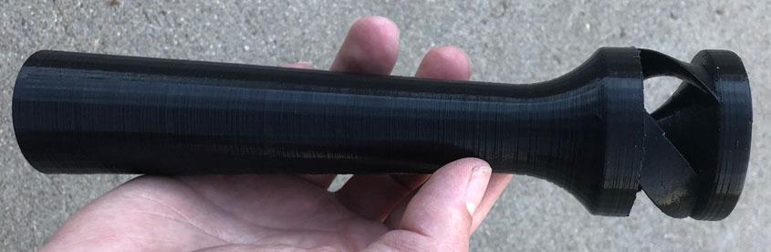
-
It looks like the bricks you might be able to get those bricks out of the housing without cutting any welds. Is that the case? If so, my first bit of advice is to change those bricks. Either to the Thermal Ceramic K26 bricks or you could roll, stuff in, and unroll ceramic blanket and go that route. (Blanket, Rigidizer, Kast o Lite, Top Coat) The current bricks will suck up a lot of your heat. It will take a long time, require more burner to heat up and won't get as hot. The standard burner recommendations to forge volume will not apply to your forge, most likely. What is the internal volume of your forge? Keep at it. Based on the look of your work, you should have no problems getting to the forge you want to have.
-
I was kidding about it not being a manometer. It is the original. I could easily get out a ruler and measure pressure in inches of water column. Not that I did. Makes a handy level as well. I too want to know more about the inlet curve. I have tried several wider and shorter curves but they weren't as successful. I know nothing on the science behind the best curve. I can't seem to find much information on the subject. If you have any information on the subject or even have a guess at what might work, I am interested. I am pretty sure we want more power to the vortex for his lower internal pressures and mixing but I haven't quite figured him out. All I know is that the current versions produce 3 vortices which feed into the main vortex in the throat and when that started, I had to jump in orifice size. While I enjoy math, there is not a lot of calculating going on over here for this. Definitely no Bernoulli calculations. Mostly a lot of observation, head scratching, research, new idea and repeat. Sometimes I stumble into better understanding, other times into deeper confusion.
-
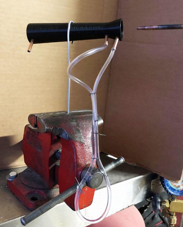
Manometer, what's that? This is just some aquarium tubing and water. Or as my coworker always says whenever anyone says manometer, "How do you measure a man?" I would use the food coloring but whenever I do, I always get caught red handed. The pressure is lowest at the throat, yes. Below ambient pressure. The pressure at the beginning of the converging section(inlet) is near ambient, it drops in the throat and it mostly recovers by the end of the diverging section. When measuring the difference between the inlet and the outlet, the inlet is just a bit higher than the outlet. The diverging section on this print had a length of 8x the throat diameter. By varying the position of the jet, I can tweak the throat pressure. I have a few more quick experiment ideas before I tinker with inducers some more.
-
If it is a password, we can thank Bernoulli for cracking the code. I imagine that required observation of several experiments as well.
-
I have recently been doing a lot of quick and dirty experiments to increase my understanding of things:
-
I use math to help make burners. The math I actually use for burners regularly is area and volume. Basic trig for angles a few times. I finally got my head wrapped around Which can break down to A₁V₁ = A₂V₂ for our understanding. As area decreases, velocity increases. More importantly, velocity and pressure being inverse, as area decreases so does pressure. We want that lower pressure to pull in all the fresh air we need. This is part of why we want a reducer at the beginning of the works. Have I ever used these formula's to calculate anything burner related, nope. In reality, we are dealing with compressible, viscous, turbulent fluids which complicate the math. I learned this math to understand the basics of what I am doing and why, not to attempt to calculate some perfect burner. My inducers have required experiments. Lots of them.
-
No problem on the work. I learned a lot on this forum and wanted to share. I look forward to your experiments and results. I think the wasp waist(venturi) is superior but I could never get it to play well with pipe after it. With your 3/4 pipe, if you stick to standard ratios, the throat will neck down to around 1/2 inch. The long slow 1:12 taper will be the mix tube. This makes the 3/4 pipe a supply line more than part of the inspirator which you just choked down. If you have a throat that matches 3/4 pipe ID and taper up from there, you end up with an outlet around 1 3/8 which makes the burner quite larger then a 3/4 pipe burner. If you cast this larger burner, you probably still need a section of pipe to distance the cast from the heat of the forge. Maybe not with a NARB. Maybe in the partial venturi ratios there is a balance point which performs better then a reducer alone. I didn't tinker enough to know much of anything here. I followed any direction that induced as much air as I could. This was so that I could push more btu/hr out of the pipe. This inevitably cranked the velocity flowing down the mix tube which requires larger nozzles to put on the brakes. It is still smaller and outperforms the 3/4 burner I used to use. I am happy with it's performance and my fuel savings. I would like to see what it would do with the proper outlet taper.
-
You are welcome sir. If you think this thread is long, I have kept a journal with scribbles, doodles, equations, and mad ramblings through the process. As to the version 3's where I did similar wasp waist experiments with the expansion after the throat, I did see some interesting/radical performance. I ended up going a different direction along my travels but I have not followed that design style far enough.
-
Nice experiments. The orange one looks good. I tried some similar experiments I called version 3.2. Do the flames look the same to the eye as they do in the pictures? Are you meaning the spiral ridges in the reducer or the shape of the reducer itself?
-
DF - In The Shop on YouTube has a 3 part series of videos about a gate valve which also diverts excess air. According to him it provides more linear control then a chopping gate valve Here is video 2 in the series which gives a good shot inside the valve:
-
I will not be omitting the possibility of a choke on any burner. My personal burners all have a choke. The burner I have which induces more air runs richer at low fuel pressure and leaner as the pressure is increased. To maintain neutral, the choke has to be adjusted as the fuel pressure is changed. Whereas v46 has a fuel volume curve and an air volume curve which more closely match with fuel pressure changes so the choke does not have to be fiddled with. The only time choke needs adjustment is to change forge atmosphere or at shutdown when top mounted. The problem with the print to metal services is expense. To use one of these services for the inducers would cost several hundred dollars per unit. I want the end cost to be lower. Maybe in the future when the cost drops it will be worth looking into again.
-
J.P.Hall, that one made me laugh. Meadowgrove, I am not sure how the layering affects flow. I will try to smooth one out to see the impact. The ridges are small enough that I suspect the impact will be minimal but you never know. Maybe the layering is providing a golf ball effect and is actually a good thing. Maybe not and it is reducing flow. Good question. Frosty, I think you are right about being down to production procedures. I have printed several since v46 whenever I got new ideas. Most of which I could not see any improvements. I have one version which induces more air but it throws off the fuel vs air induction curves. I would rather not have to mess with a choke when adjusting fuel pressure. We will keep tinkering with how to make these things reliably.
-
Blacksmithing gems and pearls
Another FrankenBurner replied to Glenn's topic in Blacksmithing, General Discussion
My ideas are unpolluted by knowledge. - Frosty -
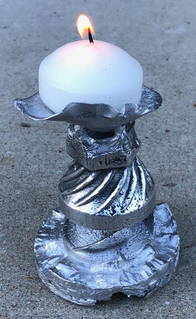
The investment failed and this was the best flame I could coax from the resulting cast. I think it is a bit rich.
-
Thanks Jerry. They were already hot, now they are sexy too. The 3D printing makes it easy so why not. Inflatable masters... silks... waxes... are we talking about burners? Interesting idea. I tried to think about the process but then I started to smell smoke. How would an inflatable mold of a complicated piece be made? Casting in two pieces and soldering them together also sounds complicated. It would most likely require splitting one of the ribs. It would also require post cast work. Though I doubt it would affect much, it would have a seam. I would probably have to thread after the cast. If we can successfully investment cast it, it will not require any post work except removal of the sprues and buffing. The threads have come out clean in a few of the pours. I still haven't given up on a silicone mold for injecting wax. Not having to print a sacrifice for each inducer would be great. Worst case scenario, we have to print for each inducer and use commercial investment. Even then, it would still be worth doing. Thank you for the recommendation John in Oly.
-
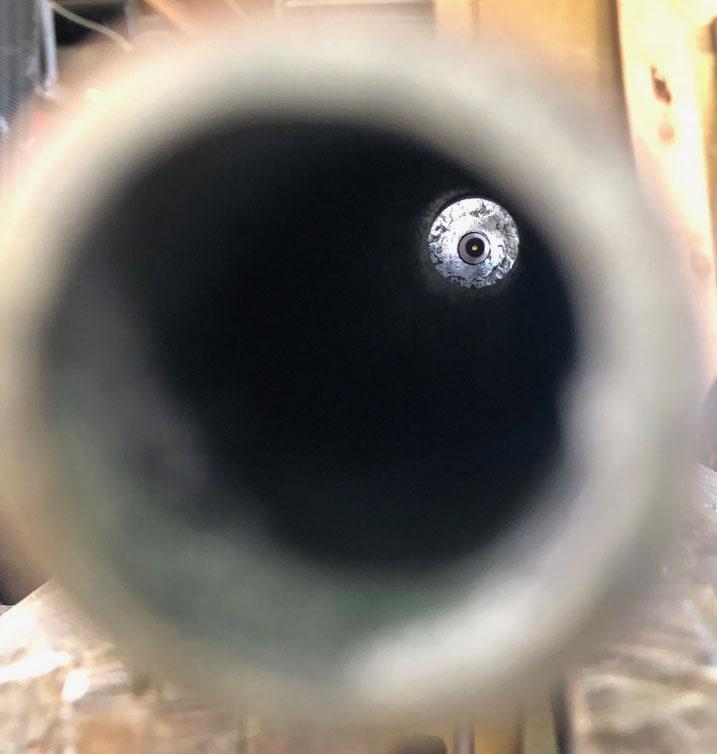
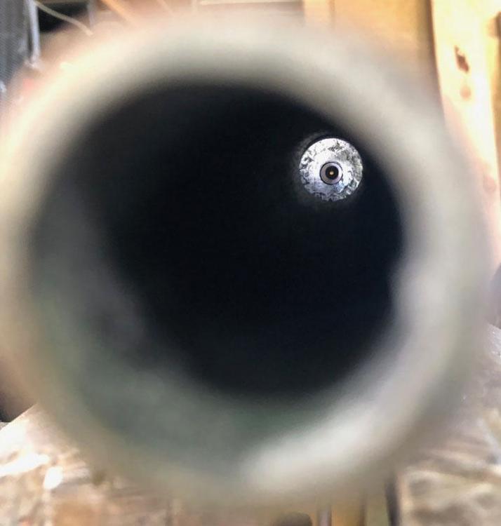
Since we are talking about the orifice/jet/accelerator assembly, I will describe my favorite way to check for alignment. It is not my idea, I read it somewhere, probably here. When installed in the burner, pick up the entire burner, point it in the direction of light and sight down the bore of the mix tube. It becomes immediately obvious when it is off. When it is in alignment, you will see light through the orifice. When it is not in alignment, you can swivel the burner around until you do see light through the orifice and it shows you how far off it is. It works especially well for mig tips and other long orifices. As you see, this orifice is pointed towards the top right of the mix tube. When your wife comes out to the garage, sees you staring into your burner, assumes you are crazy and gets that smirk they get, just yell "Land ho" to seal the deal.
-
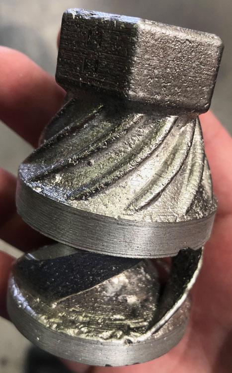
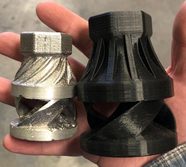
Here is a recent v46 cast: There are still some voids. You can see print lines in the good sections. We are playing with the degas process. We are also wondering about left over ash. We are going to burn out an investment and break it open to see what it looks like inside. We are also going to purchase a commercial investment to play with. I have looked into R&R Plasticast and Certus Prestige Optima. Prices vary widely. Does anyone have a recommended supplier? Here is the same cast next to the new 3/4 v54:

-
The big reason I use the 45 silvaloy(silver solder) is the extra temperature. The plumbing solder is probably mostly tin which has a melting point below 500°F. The silvaloy melt point is 1370°F. Some areas allow the use of braze joints on propane lines if the alloy melts above 1000°F. I have never heard of soft solder being allowed. Imagine a pressurized supply line letting go next to a fired forge. I have used silvaloy in refrigeration systems running 400PSI at 200°F+. Another reason I use it is because it is happy with steel, stainless, brass, and copper. It is not the only way to get things done. When compared to soft soldering the process is about the same. When I suggested silver brazing makes easy work of the orifice assembly, I was comparing it to mechanical connections.
-
I recommend learning to silver braze. It does require learning a new skill and it requires purchasing the materials but it makes easy work of the assembly. It is also useful in other parts of the build. You could braze together copper lines for the supply or braze the assembly to a connecting fitting. In the standard size burners, I turn down the threads on a mig tip and braze into a 1/4 inch steel tube. It is clean, efficient, and easy. It could be done with a drill press, a file, and a torch. Care must be taken to turn down the threads concentrically so the jet stays in alignment. In the small burner, I searched for a good fitting tube and brazed the a small length EDM tube in the end. The refrigeration access valve is what I found which also conveniently terminates with a 1/4 inch male flare fitting which I used for the burner connection. I use Lucas Milhaupt Silvaloy 450 filler and Harris Stay-Silv flux. Both can currently be purchased on amazon for $30.
-
What is your intention? Are you planning on building a small Mikey burner or trying to simplify construction or just tinkering?
-
Are you planning to use the EDM tube as an extension from the mig tip to the sweet spot jet position? Somewhere around 1 to 2 inches in length from the looks of it. I suspect that with tubing this small, as it's length increases, it's flow rate will decrease. You could increase the bore. I have not had much success with this even with short lengths. I intend on using length to control the flow rate in a 1/4" burner but suspect it will end up being between 1/2" and 1" in length. I silver brazed a short length of EDM tube into an 1/8" refrigeration access valve.
-
The jet position will not be very adjustable with this configuration. As it looks, the jet will land quite a bit further back within the burner then Mike's recommendation of 1/4" to 3/8" behind the front edge of the air inlets for his burners.
-
I too looked at any other mold method. The third rib makes that difficult. At one point, I had printed the inducer in thirds thinking a silicone injection mold for wax. I also played with inducers with only two ribs so that I could make split forms for sand but the inducers don't mix as well as the three rib version. For the open back reducer of jwmelvin's, this post has a picture of his flames.
-
As to the availability, we have to figure out how to produce them reliably and also workout all the other stuff. As soon as possible. Life stuff has this effort slowed for a couple more weeks. I am still conducting burner experiments regularly. Nozzle experiments as well. As to the running a forge with a plastic inducer, there was too much radiant heat for mine. Pointed up helps with chimney and may induce a little more air but it wasn't enough to compete with the radiant heat. The plastic melt point is too low. I suspect you are right about the NARB's doing a little better with this. Mix tube length can get the plastic a bit further away from the forge. The 3/4" burner has a longer mix tube then the 1/2" burners I tried it with. A few extra inches might make a lot of difference here. Though, the mix tubes themselves can get quite warm depending on forge design and they don't have to get very hot to make the plastic soft. User jwmelvin is using plastic reducers with a NARB running at full temperatures. He did have one go soft which he talks about on this post of his thread but he is still using plastic as far as I know. His reducers have an open back(plastic free) so radiant energy may not be hitting the plastic like it does with my inducers. He is another user to ask. He can probably provide you with more information than I did on the subject.