
Another FrankenBurner
-
Posts
620 -
Joined
-
Last visited
Content Type
Profiles
Forums
Articles
Gallery
Downloads
Events
Everything posted by Another FrankenBurner
-
It is possible. I took a 3/4"(0.824" actual ID) burner which used a mig tip and increased it's performance by going to a 3D printer nozzle. If you are over it and just want to forge, try your burner as is. Post pictures of the flame in the forge and we can try to help tune it the best it can be. If you need/want to go to new build, try a recipe burner. The easiest is the Frosty T. This will reduce the tinkering required so you can get to smiting your metal. If you are playing with a gas forge, learning to interpret flame is helpful. The difference between a tuned burner and an out of tune burner can be dramatic. A difference in forge/flame temperature, dragons breath, fuel consumption and carbon monoxide production.
-
We made a 4x4x2" mold which we line the bottom and sides with 1/2" of Kast o Lite, we pushed a piece of rigidized ceramic wool into the middle, and cap the top with 1/2" of the refractory. They have held up well as our doors.
-
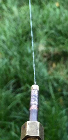
That last photo you posted, it may just be the photo but that orifice/jet looks very out of alignment. If so, that is a problem. Out of alignment, even a little, can cause major problems. If you can disconnect the burner from the fuel line and connect it to a water line, this will tell you immediately.
-
 No need to apologise. Since there are no set terms, it is hard to talk about. I understand now. One concern with doing that is that it would take away the ability for the orifice position to be adjusted. I like adjustability so that the burner can be tuned when it in it's final position. I suspect the best jet position may be different depending on the intended use (small forge, big forge, ribbon burner, hand torch). Not that I don't think it wouldn't work. I think it would work just fine with the best average orifice position.
 -
I am not quite following what you mean. Could you describe/define what you are meaning when you say injector tube and also nozzle. I think by nozzle, you are meaning the fuel orifice/jet? By injecting tube, are you meaning a divergent outlet from the throat?
-
When you say 0.036-0.040 jet, are you meaning actual diameter? I thought you were running a 3/4" injector at 035-045 mig tips with your NARB.
-
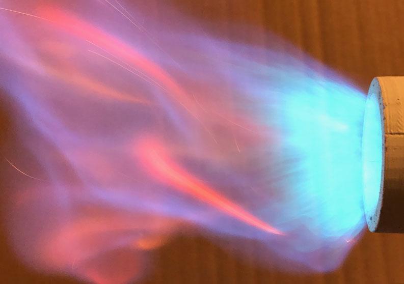
Now that I know the 1mm is measured running the forge hotter than the rest, I setup a burner in open air to take a good look at the flame. I also took a look at the same burner with the mig tips I was running previously to see if I noticed a difference. Previously I had run this burner with the 030 mig tip. I forgot I had run it with the Miller 030 mig tip because it ran better than the generic. The Millier is at 0.037" and the generic is at 0.039". With the 1mm(0.0394") printer nozzle, the flame is shorter and louder. It is exactly what Mikey describes as a neutral flame. A uniform light blue color.
-
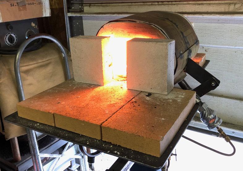
That is the "small" forge which is at 185 in³. It has 1 inch of blanket and half inch of kast o lite. The next will have 2 inches of blanket, 3/8 inch of kast o lite and a coat of plistix 900F.
-
We are using these nozzles with a printed/cast inlet chamber. In the image of the forge, you can see it. Unless I am misunderstanding what you mean.
-
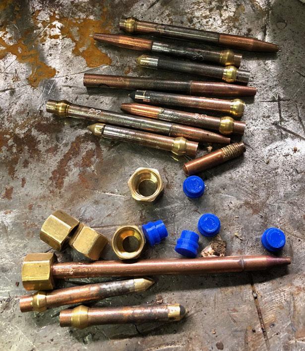
There is no dent or burr. I was excited about playing and made the connection too quickly/sloppy. The printer nozzle was brazed in at a small angle. I am a full convert. 3D printer nozzles over the mig tips. Working with brass instead of copper is great. These induce more air per orifice diameter. I suspect they are putting out more fuel as well. Thanks for the suggestion G-son. We made up several new tips with the 0.4mm, 0.5mm, 0.6mm, 0.8mm, and 1mm 3D printer tips. We drilled out a few to 0.043", 0.046" and 0.052". We have quite an assortment to play with now. The 3/8" burner does well(in free air) with the 0.8mm and the 1mm. It will be interesting to see what it does in a forge. I suspect it will back down to the 0.8mm. We ran the small forge for several hours while swapping out tips and leaving the pressure alone. It has the 1/2" burner which originally had an 030 mig tip. We tried the 0.8mm, 1mm, the drilled out 0.043" and 0.046". We listened to the sound, inspected the main flame, monitored the dragons breath, and did some temperature measuring. The 1mm tip is hands down the winner. No dragons breath, violent loudest roar, 100°F higher forge temperature. At 5 psi we are running 2450°F in the forge. It is interesting that the 1mm(0.0394") was the replacement for the 030 mig tip which measures at 0.039". On that thought, we drilled one out to 0.052" to match the 045 mig tip in the foundry 3/4" burner. This burner turned into a whole different dragon. We are looking forward to the next pour for a real test of performance. I am now planning a 1/4" burner which uses these. Maybe a smaller burner, just because I have the tiny orifices to go with it.
-
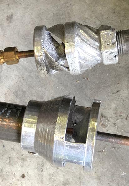
We have been testing the 3D printer nozzles as jet orifices. I had one which performed much worse than expected. I connected it to water: Hmm. We were a little quick with the assembly of this one. More care with alignment. Since I had the water rigged up, I checked several tips. Most of them were great. I had a generic mig tip which the tip itself was aligned but the jet veered off. As to the printer nozzles as orifices, the 0.8 mm and the 023 mig tip are similar bore. When connected to water, the printer nozzle stream jets out twice as far as the comparable mig tip. When put into the 3/8" burner, the flame is shorter and has a roar. It looks very good. I like it. I am going to try the 1 mm in the 1/2" burner next. I think I will have to drill out the 1 mm to larger sizes to find a good match for the 3/4" burner. You can get a few larger sizes but they are not common and the range of sizes falls off.
-
Brick House burner
-
I was meaning that the term naturally aspirated does not describe the shape of the burner tube. It simply means it does not have a powered air supply. Mikey burners are a straight burner because they have no reducer. Reil burners are constricting. The inlet constricts to the mix tube. Add the tapered outlet and you have what looks like a Venturi tube. They use the terms convergent section, throat, and divergent section when talking about Venturi tubes.
-
I had picked up on disdain for Venturi. Now I understand. Thank you for the information. It is disheartening that history is filled with so many examples of trading integrity for notoriety and a pay check. At least you can't really know about Venturi without knowing about Bernoulli. To use a Venturi flow meter, you have to use Bernoulli's equation. Not every Bernoulli is a Venturi but every Venturi is a Bernoulli, kind of thing. I think I understand what you are meaning with the mechanics. You are saying that the same dynamics which entrain air in a burner without a constriction(e.g. a Mikey) are also responsible for some of the air entrained in a constricting burner? For nomenclature, Venturi burner is an industry term. So is naturally aspirated, which is interchangeable with atmospheric, but this describes any burner which isn't blown/gun/powered/forced air and is not a description of constricting burners vs straight burners. I recently found the term inspirator but it also describes the naturally aspirated device which could be constricting or not. We can use the term waisted in lieu of Venturi, but it opens the door to "My burner is so waisted that it can't work."
-
I don't believe the curve has anything to do with the measurements of the pitot tube aside from preventing turbulence at the ports. The center port is pointed parallel and into with the fluid flow so it is being pressurized by both the static and dynamic pressure, the total pressure. The side ports are perpendicular to the fluid flow so they are pressurized only by the static pressure. The difference between the two measurements is the dynamic pressure. With these measurements, the Bernoulli equation can be solved for velocity. In a plane, you can determine your airspeed. In an HVAC duct, you can determine the air velocity which can be used to calculate air volume.
-
Great stuff happening in here. I have done a bit of research on the Venturi effect and have found nothing except the decrease in pressure through a constriction stuff. One page stated it as "Increase in fluid speed results in decrease in internal pressure." One page listed airfoil lift as an example of the effect which did not fit the in a pipe narrative but it contained the same explanation and listed gas burners as one of it's other examples. Several of the pages with examples included inspirators(burners). Several of the pages list different jet pumps as examples of the effect. If researched, inductors, injectors, eductors, and ejectors all lead to several pages which state that they employ the Venturi effect. They appear to be using similar dynamics. Unfortunately, I can not find a good source to explain what the Venturi effect is in any more detail. I found his writings converted to English but it is a deep dig. If not for the lower pressure, what is the purpose of the constricted section in the griddle burner I posted above? As to the pitot tube and Venturi, I don't understand. As far as I know, the pitot tube has nothing to do with the Venturi effect. The front port measures the total pressure which will be a higher pressure than the side ports static pressure unless there is no flow across the device. I thought the rounded front was to reduce drag. There are two tube versions which measure the stagnation pressure with a straight tube. The pitot tube and the venturi meter are two contrasting methods of flow measurement.
-
That is a long post, thank you. I will have to churn that for a day. I have to respectfully disagree with the burners not using the Venturi effect. We are forcing fuel down a constricted pipe and using the resulting low pressure to draw in air. This is interesting and I am quite curious about it. I am planning several experiments to understanding more about the basics.
-
The read somewhere that the measuring venturis typically have an inlet cone of 30° and an outlet cone of 5°(included angles) to reduce aerodynamic drag. This would give you a throat angle of 200° which isn't very sharp. That is provided the cones line up. These venturis have a different intention and a lot of them are used in applications where the stream being measured is moving in relation to the venturi. Page 17 of the 3D printing thread, member BriJasher links a couple of videos talking about the purpose of a trumpet/bell shaped inlet for turbine engines on a test stand. It deals with efficiently inducing non moving air into an object with a static position.
-
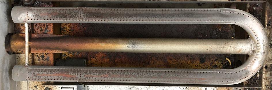
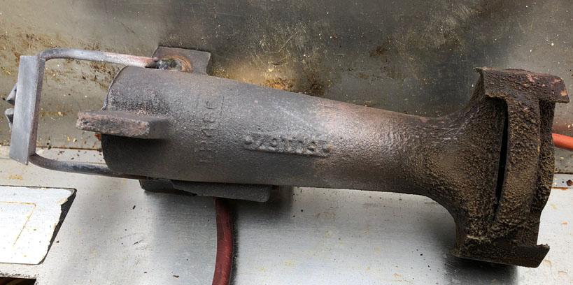
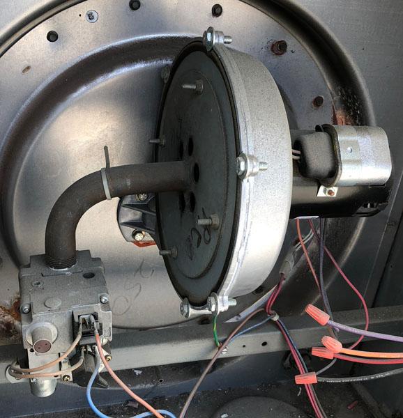
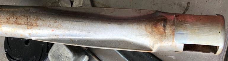
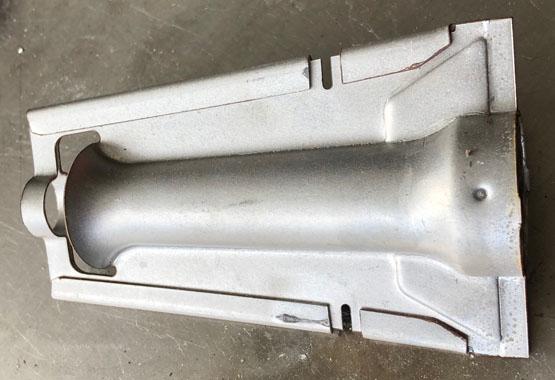
Yes, but it's fun. It's kind of the blacksmith burner way. Trying to squeeze as much down the pipe as possible. More btu's without staying within those confines is easy. We are reinventing the wheel back to the venturi burner but it isn't a fair fight. Venturi burners are almost the only NA burners I see commercially. I have been experimenting, trying to increase my understanding of the inner happenings. I originally thought the outlet taper was about reduced downstream drag and vortex geometry but the more important thing happening is the increase in static pressure of the FAM at the delivery point. Now I am trying to determine how changing the inlet reducer shape, throat diameter, and outlet taper length changes the static pressure, what the limits are(and why), and what this does to the flame. As Frosty stated, it's an endless journey. I took a handful of pictures of some of the commercial burners I have seen recently . These are all low pressure, relatively large orifices, and low temperature application. This guy is one of 20 burners which were in a large HVAC unit. This one is out of a large griddle top. The orifice is behind the wall on the left size which feeds into the venturi under the cross bar. Here is a shot of that venturi, after I cut the burner apart. This big cast guy is for a pizza oven. IIRC he is 170,000 btu/hr. He is a blown burner. I thought this one was neat. It is the only one that I have seen like it. It was on an old condemned HVAC. On the lower left you see the gas valve which is plumbed right into the blower housing. The orifice discharges into the blower suction and the blower mixes the FAM as it is delivered.
-
Question for Frosty, do you happen to know what that final pipe size is in the forge you posted? Thanks for the information Billy. Are your water cooled NARBs something you are keeping close to the vest or are you willing to entertain the curious? As Mikey stated, your mix tube is mostly 1 inch pipe. I suspect this burner will need a larger jet, probably a bit larger. Full length tapered mix tubes can not be categorized into the same size categories. The commercial burners I deal with are all rated in output capacity(btu/hr). Not so easy to determine in your garage. If you are using mig tips, you could compare to pipe burners which use the same tip at similar pressures. I am playing with similar. The small tapered tube we cast is an adapter for half inch heads to a 3/4" mix tube. I am able to go to the 045 tip in this burner. I also have a straight 3/4" head(No tapered outlet from throat or spiral vanes) which induces similar air using the same jet. I am now trying to figure out if there is much of a difference in performance(possibly in different applications), how so, and hopefully why. I look forward to your results.
-
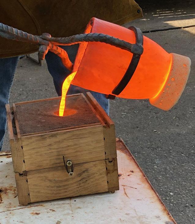
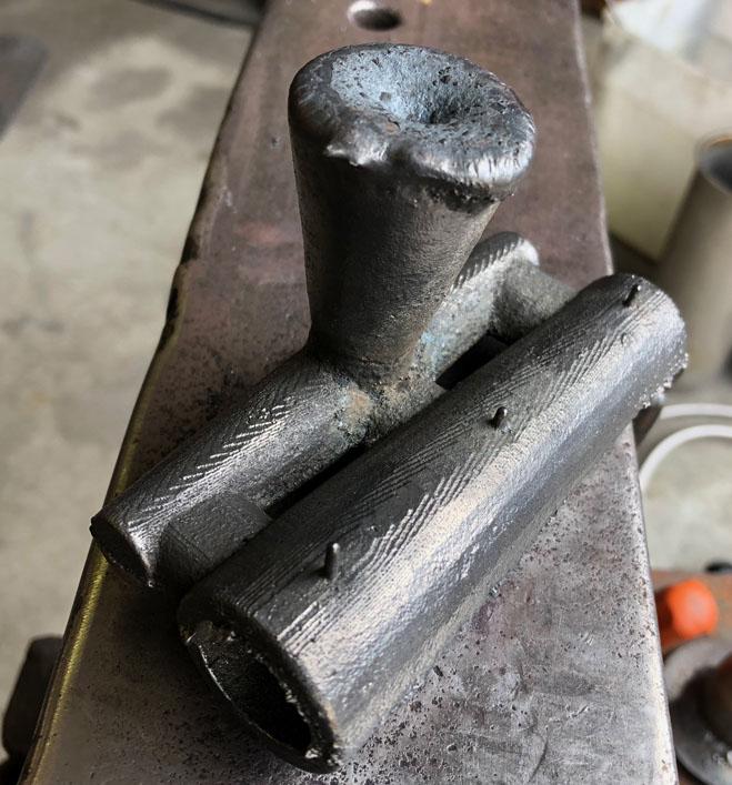
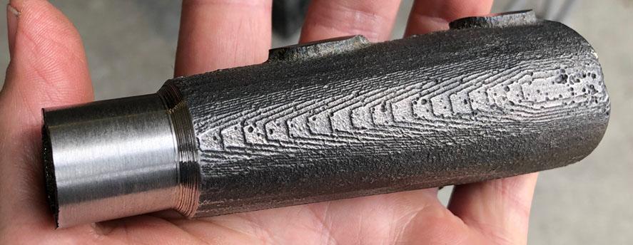
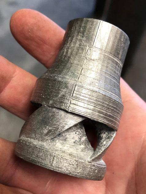
I stated what I meant quite poorly. I did not mean to imply stronger vortex and more air induction can't be had together. All I meant was the more energy spent on vortex, the less there is available for induction. Energy in = energy out. The wasp waist burner is a great example of using that energy more efficiently. Do you suspect that the reason the wasp waist does so well is because it promotes stronger vortex or simply because of the drop in resistance? Maybe ribbon burners are superior because of their shorter combustion zones? For a single port, I am picturing some kind of fire tube between the burner and the forge. A nozzle extension of sorts. When I first heard the term, I did some googling. I found a bunch of corset styles. At the time I assumed it was where the term came from because of the likeness of shape. WIkipedia Wasp Waist. Those look extremely long compared to most of the commercial wasp waist burners I have seen. Quite neat. I will have to get some pictures of the burners I see quite often. Today was a good day. Our first successful iron cast: The three little nibs are from pinhole air vents. We were not hot enough previously. We up sized burners: The top is one of our first investment casts, the bottom is burner was cast yesterday. It is another experiment. The casting has improved a bit. With more btu's and more patience, the metal was a bit hotter this pour: Here is another shot from the bottom after some machining. It still needs a bit of work.
-
Version G1 runs rich with the 023 tip. The flame is a bit unwieldy and dispersed for a hand torch I would think. If the orifice size were better matched, the flame would be smaller and shorter. Maybe useful if wider area lower outputs were needed. Though I wonder how stable the flame would be if we started to lean it out. Welcome aboard Phil. No STL's have been posted. If you are good with CAD, read though some of the pages and you can get a good approximation as a starting point. Here is v73 in aluminum. Still needs the investment cleaned off. He is a 3/8" guy. You can see the misalignment spots from the 3D print in the surface.
-
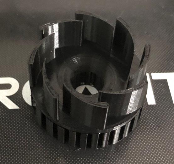
This first version was made to match G-son's mental image. It is a perfect example of the need to encourage not force a vortex. We successfully increased the vortex energy. In doing so, we decreased the entrainment energy. This will always be the case and has a balance point. We want to use as much energy for air entrainment as possible while only using as much as needed for the vortex to do what we want it to do. We can find the most efficient way to give the vortex energy and then find the balance point. We can make the vanes taller and/or decrease the quantity to increase the inlet area which can induce more air but as we increase inlet area, we decrease air velocity. We want this, as any restriction that increases velocity is decreasing total air entrained. The downside is that as the velocity lowers, the momentum decreases which makes it's path much shorter to the low pressure zone. It sounds like we are going to 3 vanes for vG2 and possibly taller vanes for vG3. One thing I can say about this version, the radiant energy felt on my face while standing near this thing is much higher than the versions concentrating the flame forward. It makes me wonder how the vortex flame will act inside a forge.
-
The front half of vG1: It is very cool looking. It's air entrainment is pretty low as expected. More power to the vortex is obvious in the flame. It is a squat wide rotating flame. It is a bit mesmerizing to watch the secondary flame dance about.
-
It's your idea, let's stick with the original first. After that we can try 3 vanes on version G2 if you like. I will have to try Frosty's no vanes idea as well. I am having a hard time picturing this one. I think I follow with the cutting of the cans and offsetting the outside shell. I get lost at the point of adding this to the reducer and how the air enters. All very awesome. From what I can see, it is hard to discern improvements. They all look like serviceable flames. I like the contrasting flames of the Funnel A/New Choke and the 5 fin choke. The Funnel A/New Choke picture shows a flame that is darker blue, straight, longer, and more pointed. It is moving faster and it's secondary flame is straight and more transparent. The five fin choke picture shows a lighter blue flame, which is shorter, more cylindrical/blunt, and a secondary which is larger, fluffy and has rotation. The flame is moving slower. The nozzle is hotter in the vortex flame burner picture, which may be responsible for what looks like more secondary flame. I have seen the secondary flame go from invisible to highly apparent once the nozzle heats up. In actual forge use, as a single port burner, I am not sure which flame type would perform better. According to the burner technical papers, a flame which is burning shorter/smaller (provided the same fuel amount) is liberating more heat per flame area, it's hotter. This is assuming the flames are burning the fuel efficiently. With the larger secondary of the vortex flame, we don't know if this is the case. My mind is churning with new things to test, this stuff is great. Thank you for posting. I saw the original post with all the ribbon burner tests as well, I would be glad to have any one of those heating my forge.