bertie_bassett
Members
-
Joined
-
Last visited
-
Its always amazing how valuable a good drink is. I do a fair few of odd jobs for friends and neighbors, never like to charge money but always happy to receive a beer or scotch.
-
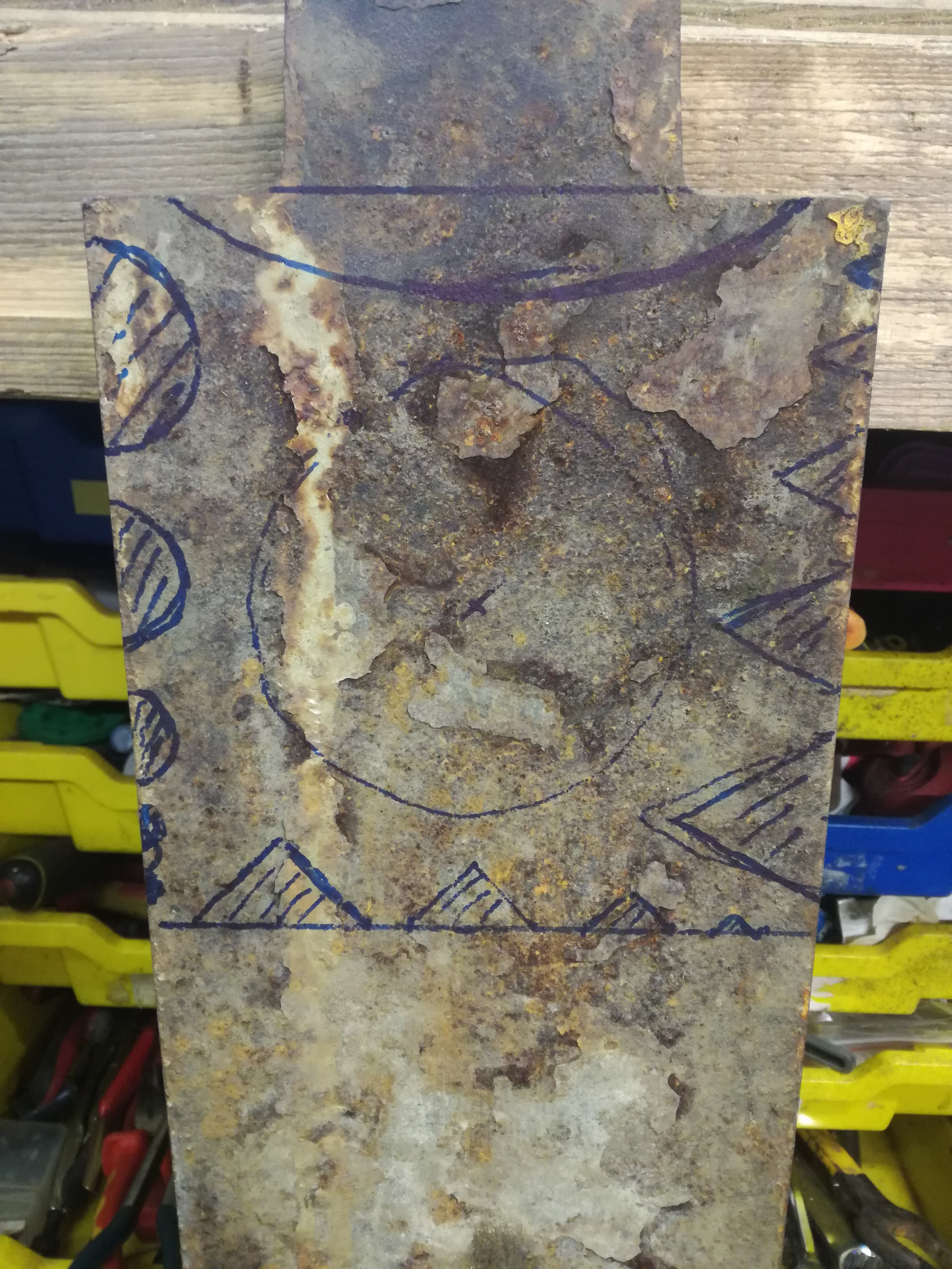
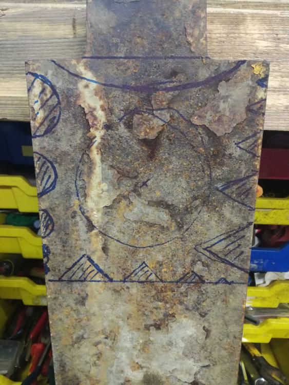
Yes thats what i was thinking too, the triangles sketched on the right side are 60 ish degrees. Looking again i need to rethink the sizes, 2" is far bigger than anything i'm likely to need. Dont want to lift it more then once so need to decide and commit to something
-
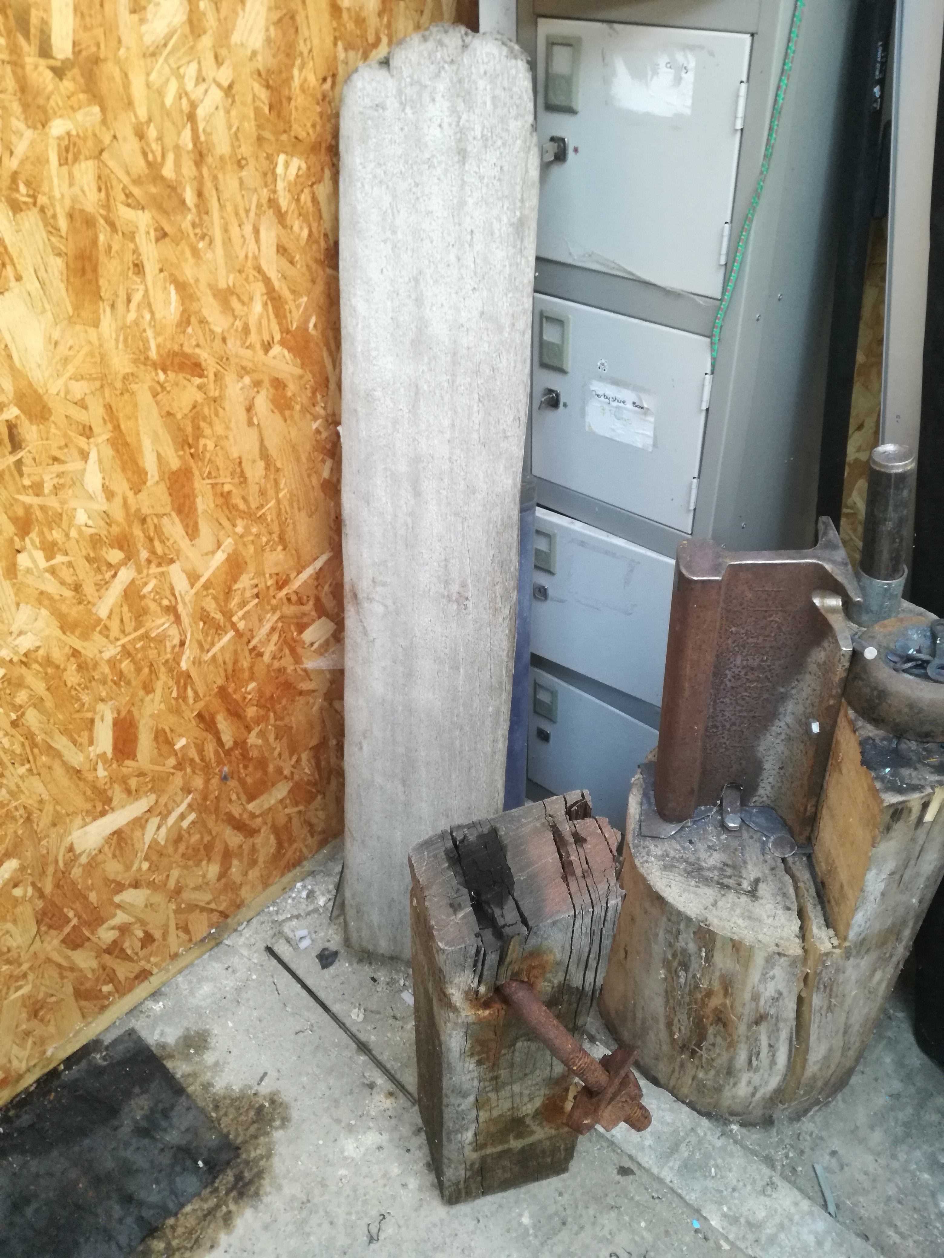
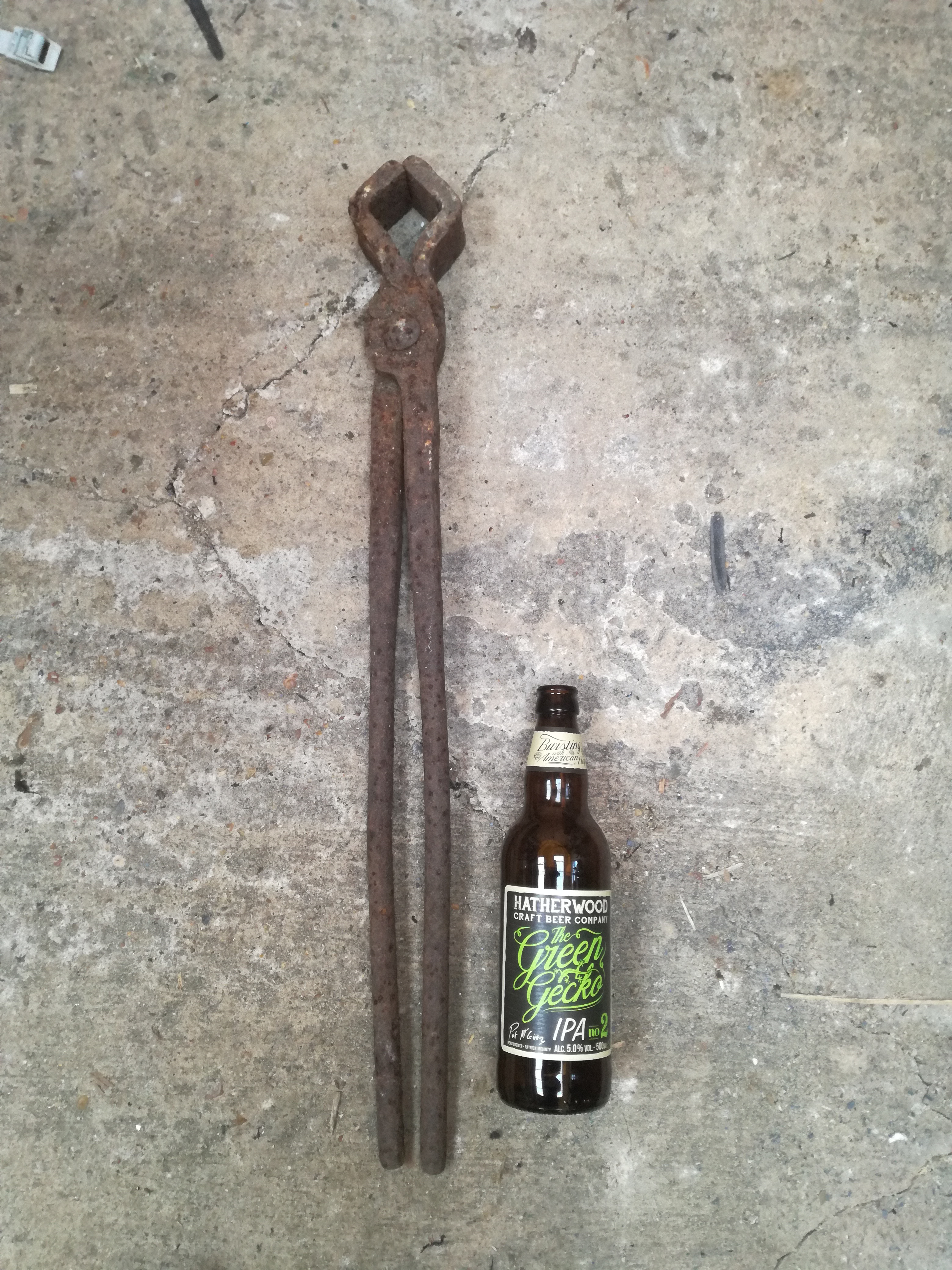
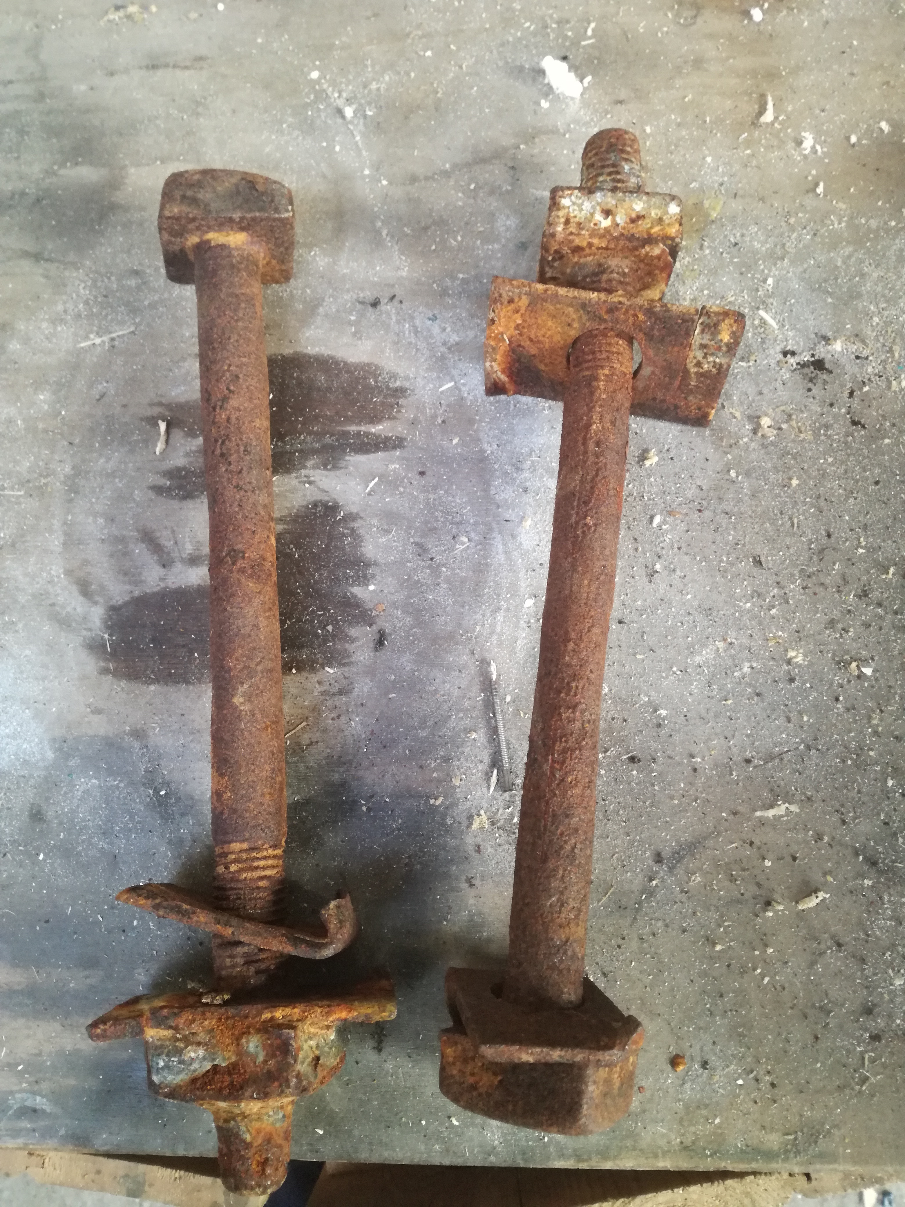
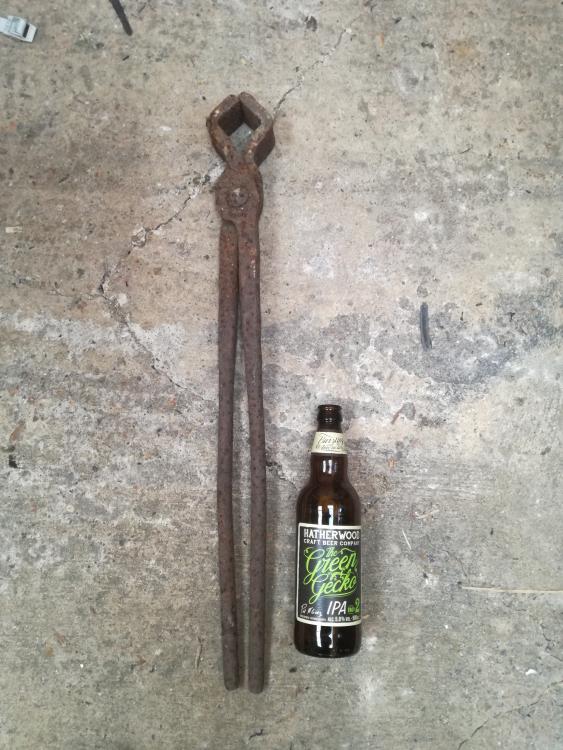
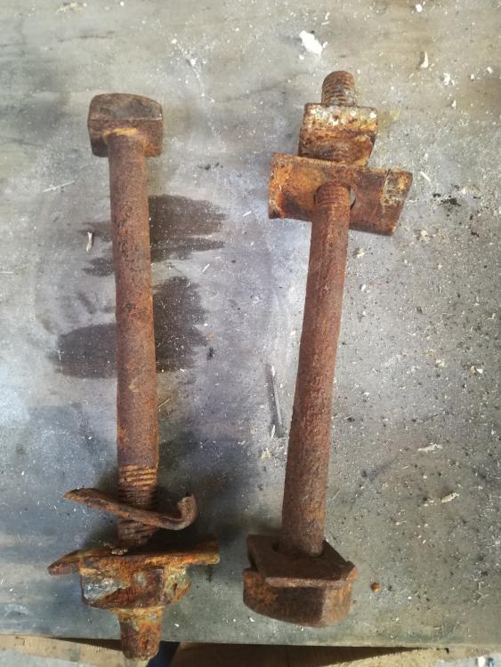
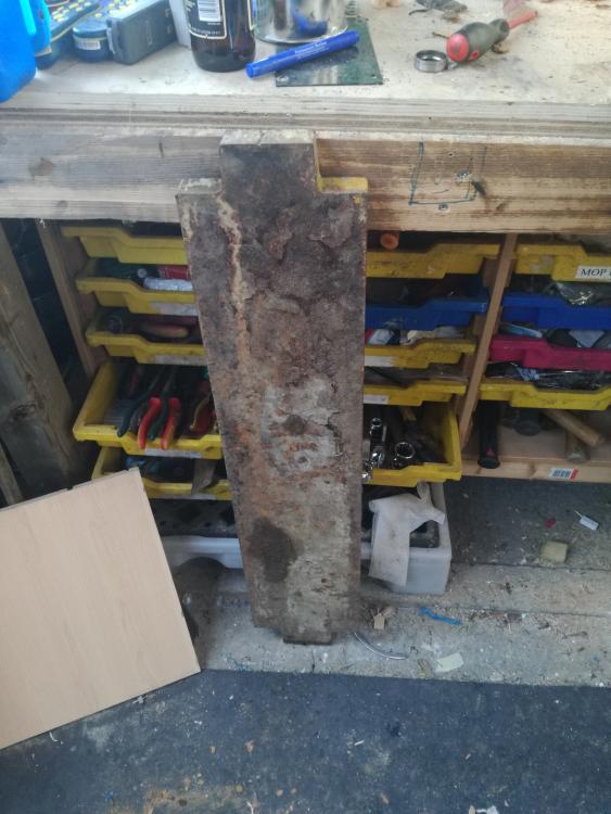
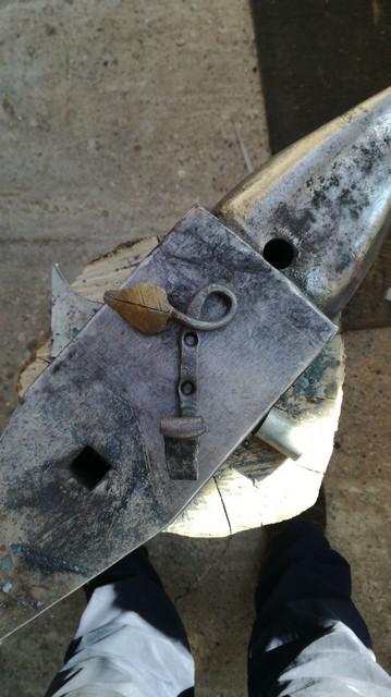
picked up a few bits on my travels recently, the wood and large bolts are reclaimed from set of groynes off the Norfolk coast. I assume the bolts are something other than mild steel as they haven't corroded all that much. Might see if there is a mantle piece hiding in the wood but chances are it is too badly split. The big lump of steel is 8" wide by about 1.5" thick looks to have been cut with a torch so it steel rather then cast iron. suspect its tractor related as found it on an old farm. may try machining it into a swage block but open to suggestions. and as for the "tongs" they were in a valve house next to very large 1930's water tower, think they were repurposed from elsewhere and used to turn a square valve stem.

-
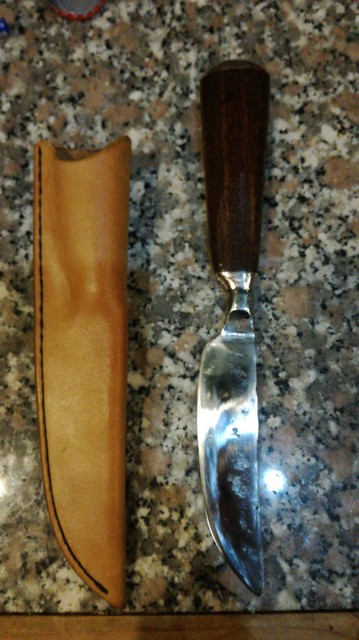
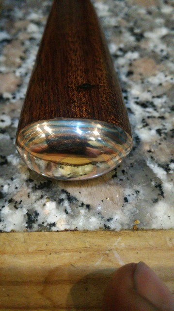
Been at this one a few days but just finished it up for a friends 21st.

-
would using the split cross method not work if you simply do not overlap your splits? if you leave leave a solid piece 1/2 your stock thickness then i think it should all match up. alternatively upset the middle of a bar and then draw out the arms. seems a hard way to do this though.
-
pnut, that's a handy little anvil and the horn looks a lot more cone shaped then mine! for mounting i simply made a 6mm thick washer and lag bolted it down through the holes in the base. seems to be holding up fine although i should have used some lead or caulk to dampen the noise a bit.
-
Neal - try using a mix of 10p's and 2p's the tens are a cupro nickle and are only a tad smaller than the twos. Gives a nice silver and copper mix althought the brass looks nice too
-
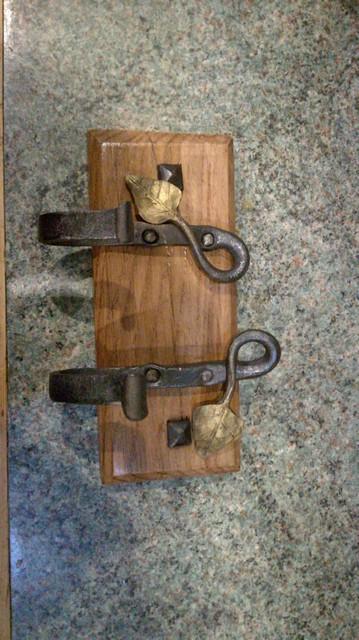
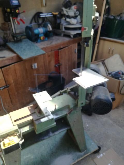
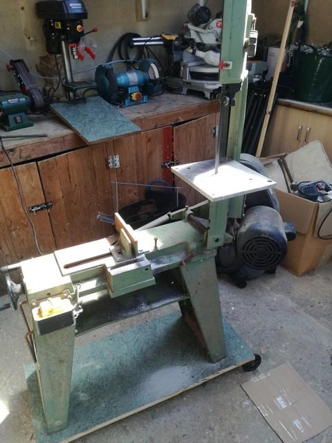
those faces look to have welded on well David. iv had this week off work mostly been putting up fencing but managed a few jobs on the shop. first up was a table for my bandsaw when in vertical mode. Made it a lot more complicated then it looks and spend a fair bit of time on my mill but should work nicely. the mains part is bolted permanently and lets the saw be used in horizontal mode, the front section slots on when needed. after that i managed a bit of time at the anvil. knocked up a test hook and then couple of hooks for my sisters birthday, i punched a hollow then drilled through on the final hooks but perhaps should have just used a smaller punch. surprisingly making four small nails took me a lot more time then i thought but got there in the end. the square ones are just dummy heads to hide the mounting screws.
-
you could always bolt a bit of square tube to the heel area, rather than welding. you should be able to drill and tap the wrought iron body without too much trouble. Its only there to stop the tool moving around, the anvil itself will take the pounding. another option is to drive a bit of sq tube into the base/stand, would need to be at the side rather then the heel to get a straight drive down to the base. or you could just forgo the hardy hole altogether and just make saddle tools. lots of way to skin the cat.
-
-
many thanks Pnut, im sure those links will help a lot of newcomers get started without the need for going out unnecessarily. i keep thinking of a 55 drum forge myself but could never find the link. Got too many other jobs at the moment though, plus still working full time so it may be a while till i get some shop time.
-
-
if you can mount it solidly at the right height im sure it will feel a lot better and help you on your learning curve. another option perhaps for the future might be to flip it 90 degrees clockwise ( as viewed from the first photo) and then build a base to hold and support it solidly. the working face would be smaller but it would have more mass under the hammer and you would also be able to use the round section as a horn for drawing out. for now the big wide surface will help you to position the work and not be dropping things all the time whilst learning.
-
indeed its an easy mistake to assume that the fittings and manufacturing process will all be true and parallel. a quality fitting should be fine but even known sources can cheap out on parts and cause issues. fortunately it is easy to check most of these things prior to drilling and to accommodate manufacturing 'features'
-
when you go to make your t burner check over your fittings first, i put one together last weekend before i realised the 'T' had been tapped crooked. looks good from a distance but means the mig tip is misaligned and the jet will hit the side wall. good job i bought two of everything, next time ill chuck the mixing tube in the lathe rather then using the T itself for alignment.