

Steve Sells
-
Posts
9,156 -
Joined
-
Last visited
Content Type
Profiles
Forums
Articles
Gallery
Downloads
Events
Posts posted by Steve Sells
-
-
IForgeIron Blueprints
Copyright 2002 - 2011 IFORGEIRON, All rights reserved
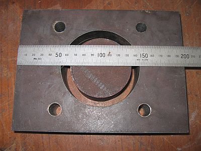
BP0674 Hardie Tool
by Irnsrgn
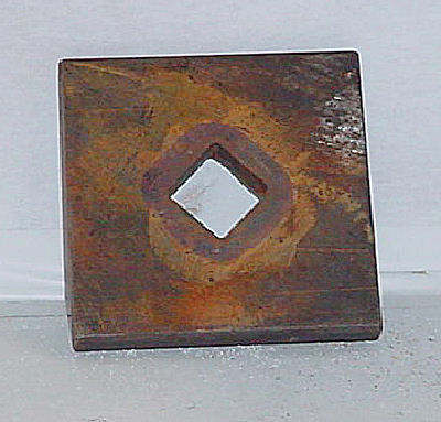
The Hardy Hole in my main forging anvil is worn from years of use by me and its previous owner, and if I fuller down the collar in the hardy hole it will only fit well one way, so I made this Hardy Collar Fullering plate that I put over the hole prior to fullering the shanks. Its just 1/2 inch hot rolled flat. Besides my hardy hole is 15/16 square. Its evident by looking at it that it has been used a time or two.
-
IForgeIron Blueprints
Copyright 2002 - 2011 IFORGEIRON, All rights reserved
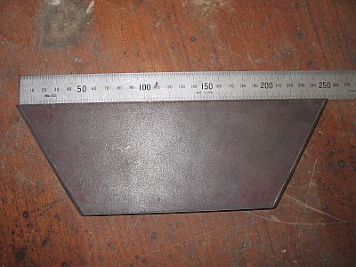
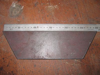
BP0675 Hardie Tool 3
by Irnsrgn
When I make Cut Off Hardies I orientate the cutting edge 45°to the square hole, that way you can stand in one place and use it instead of having to move to one side to get lined up.
The cutting helper is a plate fixed to a piece of rod that goes into the prichel hole. When you use the hot cut, raise the plate, rotate it over the hot cut and hit the plate with your hammer. This protects the hammer face and provides a square hit on the hot metal.
-
IForgeIron Blueprints
IForgeIron Blueprints
Copyright 2002 - 2011 IFORGEIRON, All rights reserved
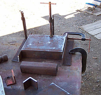
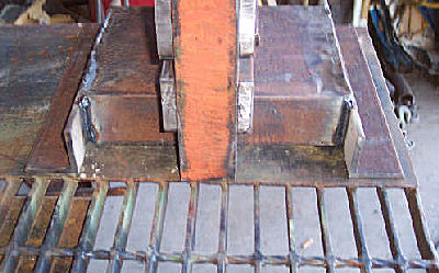
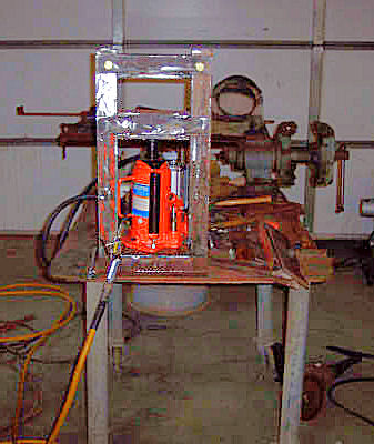
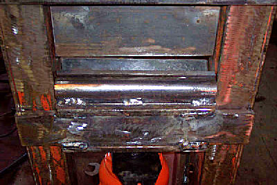
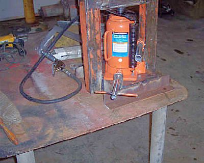
BP0676 Press
by Larry McCollum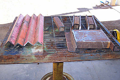
Front of the press
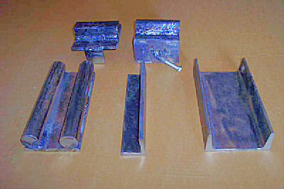
Shows press brake dies. The lower die is a 3/8" x 3 1/2" flat for the base, with 1 1/16 round welded to it. I can lay a piece of angle between the rounds for sharper bends. As mentioned above the upper die is just a 1/4" by 3" flat on edge.
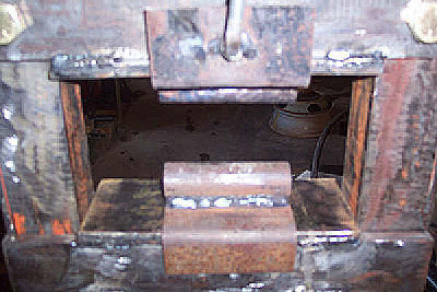
Shows lower die with out the angle insert. The upper anvil has been flipped over and the upper fuller die installed.
Same as above with the lower die replaced with bottom fuller die.
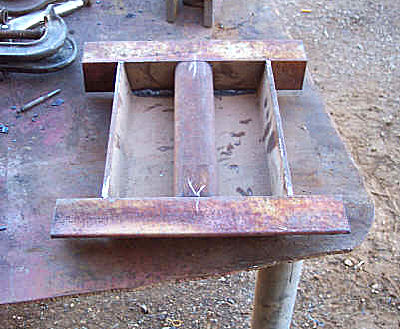
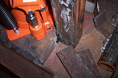
End view of the lower dies, 4" channel and round stock welded on flat iron base. With fuller dies behind.
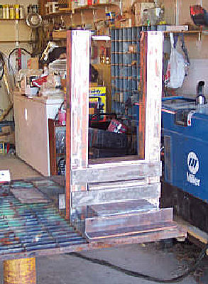
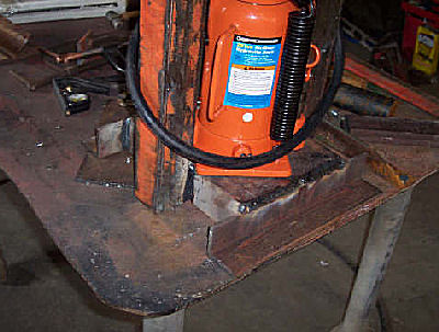
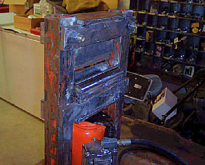
Rear view of the press.
Base clamped ready to weld the ends.
Two angle in a vise ready to weld in square tube for uprights.
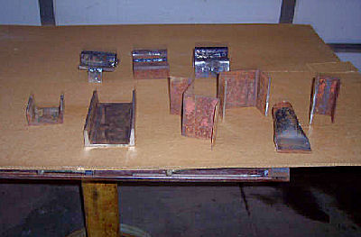
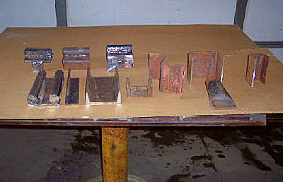
Cut angle for uprights ,8" x 10" channel base, 2" square center support, material for upper and lower anvils.
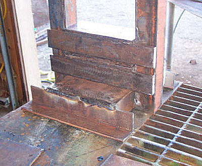
Under side of the base showing center support in the base.
General pictures press tack welded before final welding.
After finish welding.
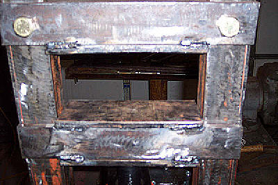
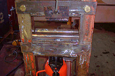
Shows upper anvil secured with 5/8" grade 8 bolts.
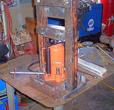
The finished press.
General pictures press tack welded before final welding.
After finish welding.
Shows upper anvil secured with 5/8" grade 8 bolts.
The finished press.
-
IForgeIron Blueprints
Copyright 2002 - 2011 IFORGEIRON, All rights reserved
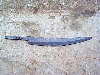
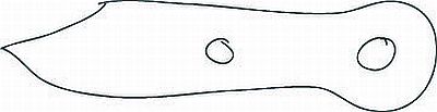
BP0677 Making a knife
by Sam Salvatia tutorial on how to forge, grind, and mount a sashimi knife, which is a knife made for slicing sushi, but is also VERY handy for slicing anything else also. The chisel type geometry (flat on one side and flat ground on the other makes it possible for VERY thin slices. Enjoy!
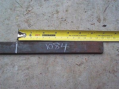
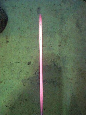
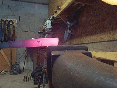
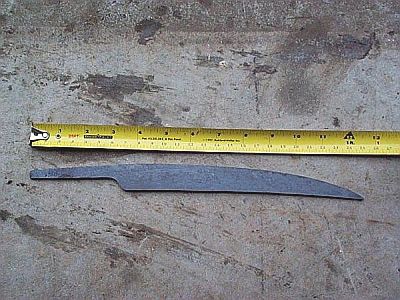
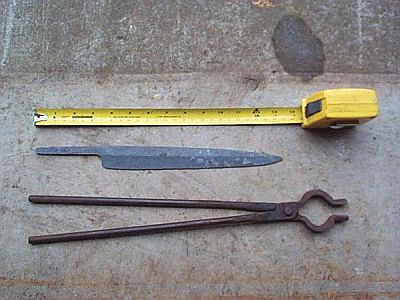
First off I start with my steel, in this case I will start with 1084, a very excellent plain carbon steel. It is said to be the best beginner steel, as it requires little to no soak time when heat treating, and can be quenched in oil or better yet automatic transmission fluid either heated to 120F (or for best results a PROPER quench oil) I start with a 7 inch piece
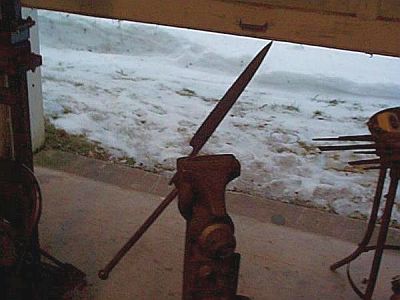
, meaning it orients in my hardy hole at 45 degree angles, as well as the edge being ground to give a flat or 45 degree cut depending on how you have it. I use this anvil and my big anvil to work on.
Here is my hot cut, and my anvil. I made this hot cut from a section of leaf spring, it is a double 45 degree hard
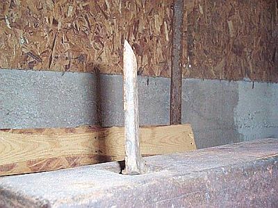
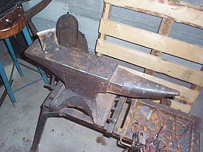
I use my hardy to put a notch at the 7 inch mark, you can just slightly see it in the next couple of photos. I only put a notch FIRST as I want to be able to hang onto the bar of steel instead of using tongs which can be clumsy. I work down the tip first.
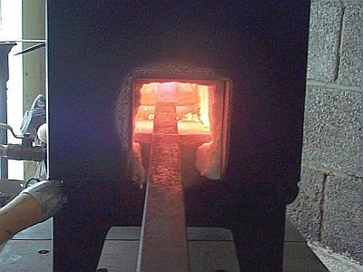
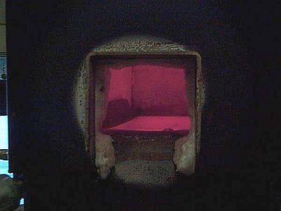
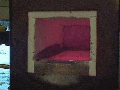
INTO THE FORGE!!!!!!
And work down the tip.
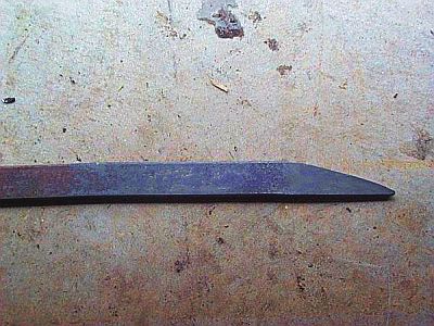
Next I will work out the profile taper. Make sure to take care and keep the bar the same thickness, we will add the thickness taper later on.
Profile taper
The thickness is a nice and uniform 1/4 inch for now.
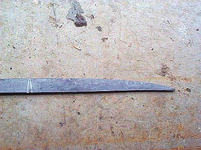
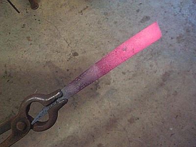
Now I will hot cut the profile tapered blank from the parent bar. When you do this is your own personal choice, I should have waited until I was ready to forge down the tang but oh well.
Getting ready to hot cut.
Cut almost, ALMOST all the way through, then twist off the rest, this way you will not ruin your hardy's edge or mar your hammer face.
The cut off blank.
Next you will start and draw out your tang. "Drawing out" simply means stretching and squishing the metal out in length. I take a heat on the end of the bar, then set the amount of material I want to turn into the tang over the face, and leave the rest hanging out over the edge. I will hammer down angling the piece so I get a nice smooth transition, I use the part of my anvil's corner that is rounded so there is not a sharp corner which could be a stress area.
Set it over the edge and face
Then HAMMER! Hit it good, but be careful not to go too far or you will end up with a needle for a tang
Next draw out the tang. It should be widest at the shoulder, tapering in thickness and width towards the end.
Back into the forge first

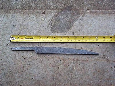
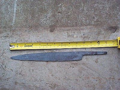
The blank so far, profile taper but no thickness taper yet, the tang is drawn out.
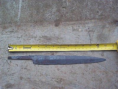
So far from the original stock size I started with the blade has grown from it's 7 inches out to 12 inches, mostly from drawing out the tang but from profile tapering as well. I let this growth happen on it's own, though there is ways to calculate how much stock you will need, which you will need to know if working to a specific design or size you want in the end.
Now we will go back into the forge and add some distal taper. Distal taper means thickness taper, the blade will go from thickest at the shoulder area to thinnest at the tip.
Back into the forge, then forge down on the flats all over to taper the knife. You will start with only a few hits on the base of the blade then move out to the tip where you will hammer more. The more you hammer one area the thinner it will get, so logic says hammer the tip more than the shoulder area. Here is the blank tapered (looks like not much but the shadow didn't help).

Now here we are, we have our blank. Forged to shape, tang drawn out, tapers added, we are ready to forge our bevels.
The blank has grown another 3/4 inches from adding the taper
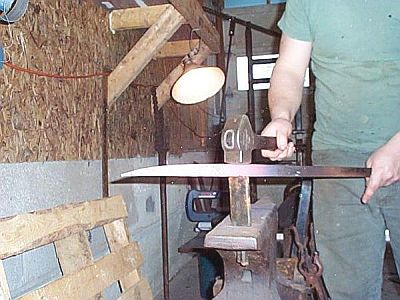
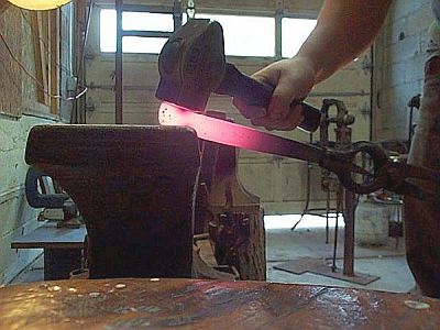
Here is how you would hit it if you wanted the bevel on both sides, both the piece and hammer are angled. You will get the feel of this better with practice, but you should and will be able to hold both at the same angle intuitively to attain the same bevel on both sides. But the action itself will also assist in getting both even.
Now we begin our bevels. I took two shots to illustrate (as well as finally have a picture on hand of this) the way you would do it if you wanted to form a bevel on both sides of the blade or on one.
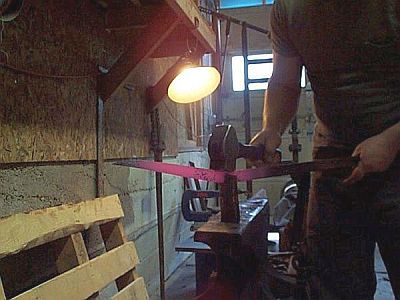
But for a sashimi knife where the geometry will be a chisel grind (flat on one side and beveled on the other) I will hit like this, with the piece flat on the anvil and the hammer angled only.
Here is the bevel beginning to form, I start with a small one on just the very edge then work it back towards the spine angling the hammer less and less.
And here is the blank with the bevels rough formed so far, looks like a sick banana!
We are going to have to straighten before we go any further or will end up with a skinner. My method of straightening is I will form the bevels, then straighten. Some will straighten as they go along, but I find it easier to do it this way. I use a 2x4 to straighten by hammering it onto the edge, it is wood so it does not mar the edge you just worked down. I got this idea from watching an excellent smith by the name of Mace Vitale at Ashokan using an old baseball bat to do this (thanks Mace!).
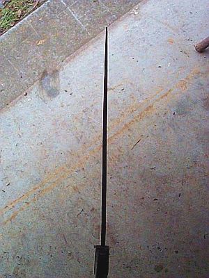
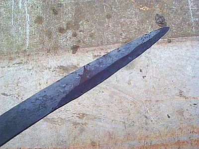
Here is the straightened blank, I then worked the bevels again to refine them further then straightened with the 2x4 again and here we ar
Here is the flat side
And and overall shot of the blank so far
The blank has grown now into a blade, and also grown even more in length. What started as a 7 inch bar of steel is now 13 3/8ths long, almost doubled in length.
Right now there are all kinds of stresses built up from the forging process in our steel, and we need to fix that. We fix this by normalizing the blade. Normalization is where you take your blade and heat it up evenly to non magnetic (where a magnet will not stick to the steel anymore), also known as the critical temperature, then go a little hotter then pull the blade from the fire and let it air cool. This brings all the carbon and alloys into solution with the iron, then let's it all relax back into they're separate places. I do 2 normalization cycles, some smith's rule of thumb is 3 but since I will do one more before heat treat and I was careful with my working temperatures I will only do 2 now.
WHEW what a long day!!!!! Now we have our forged knife, it is forged to shape, tapered, and beveled. Hopefully you kept a careful eye not to work your steel too cold or too hot
then air cool
Second

And let it air cool again
And we are all done for part 1 which included the forging process, part 2 which will include grinding and polishing, heat treating and mounting and final sharpening will continue soon.
The timeline you are looking at here was about 4 and a half hours, but only cause I had to go refill my propane tank, as well as take double heats sometimes to get a picture or two in
-
IForgeIron Blueprints
Copyright 2002 - 2011 IFORGEIRON, All rights reserved
BP0679 Armadillos
by Rikasso

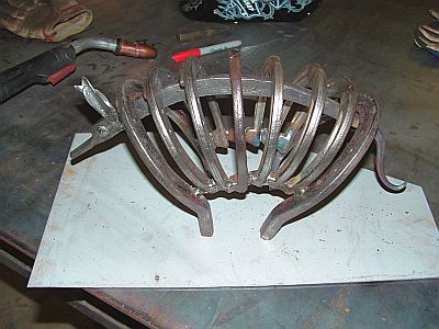
1st You will need 9 horse shoes, 3 large ones, 6 smaller ones
Take the smaller shoes and weld them together as shown in pic (the steeper the angle the more it will curve the back)
Weld one of the larger shoes at each end as per picture this creates the legs.
heat the bottom part of each leg one at a time, and bend to make it look as if it is walking.
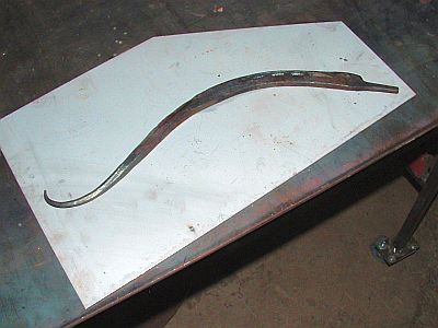
take the third large horse shoe, and straighten it out, next draw one end out to a nice taper. Then turn it end for end, and create a step using half hammer face blows on the near edge of the anvil to about half the thickness of the horseshoe width. Draw out, and round it out for the snout, and set aside.
Take two pieces of 3/8 round, and make a short diamond taper about 3/8 to 1/2 inch long (as if you where going to make a leaf) the next step is to flatten out the taper whit the crosspeen (to desired look it’s for the ears) then shape them on the step of the anvil or swage block (if your lucky enough to have one) Now cut the ears you just made off, and set aside.
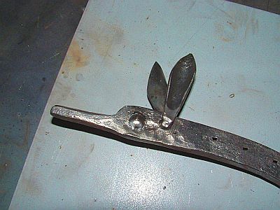
Take the large shoe that you straightened out, and bend it to the curve on the inside of the Armadillo’s back (it’s now the spine, head, and tail see pic) Weld the ears in to place, next just a spot weld on each side for the eyes. Weld the whole thing on the inside of the Armadillo leaving enough sticking out both ends.
Last but not least heat the tail, and shape to desired form (twist it, curl it, or just have fun)
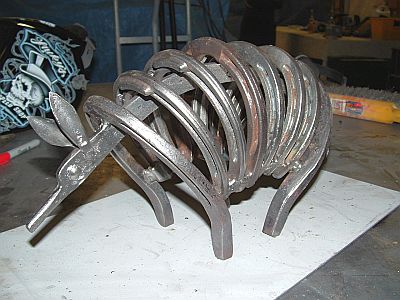
I hope this B.P will entertain you, and maybe inspire you to make other creature out of the same elements. Pigs, Caterpillar, Cows, and so on enjoy.
-
IForgeIron Blueprints
Copyright 2002 - 2011 IFORGEIRON, All rights reserved
BP0681 Upsetting
by Mark Aspery
There is a formula that I was taught to help 'stabalize' the material during an upset.
"Only heat 1-1/2 times the thickness of the stock"
So for 1/2 inch square heat 3/4 inch long section.
For flat stock heat 1-1/2 times the smallest dimension.
For 1 inch by 1/2 inch flat bar - heat 3/4 inch long section.
In a gas forge this means judicious use of a quenching medium to isolate the heat.
You can further stabilize a bar when upsetting the bar end by drawing a slight taper to the end (On the face of the anvil). This will thicken the bar and negate having to correct for any growth in one dimension for a couple of heats.
I'm not a big fan of the upsetting 'tool' per se as I find it can leave sharp transition points.
You could try forge welding a collar on.
-
IForgeIron Blueprints
Copyright 2002 - 2011 IFORGEIRON, All rights reserved
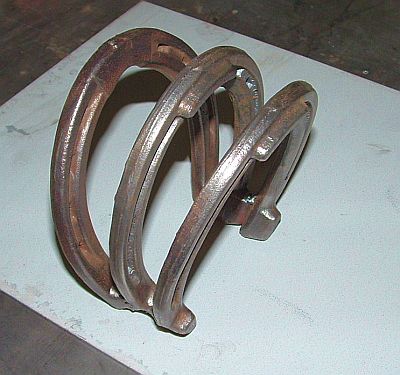
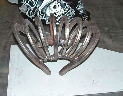
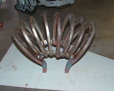
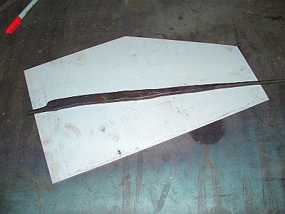
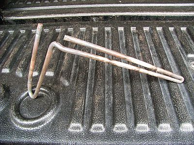
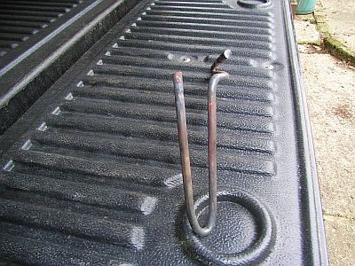
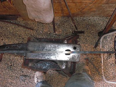
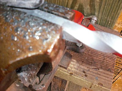
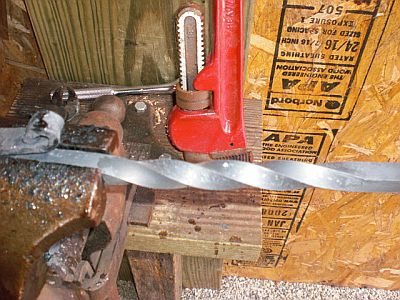
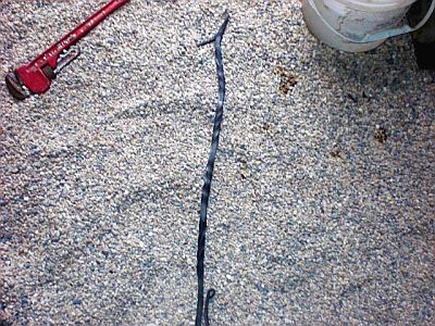
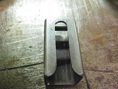
BP0682 Spring Fuller
by GNJC
I'm sure someone else has made something like this, (apologies to inventor if I've sub-consciously 'lifted' an idea).
It is easy to make & very useful so I'm putting this on the net to help other short-handed & short-tooled smiths out there. All are welcome to use this.
The photo's should explain how to make it, but I add 3 points to remember:
1) Using mild steel is alright, but it doesn’t last long; re-bar is better; old spring steel the best yet.
2) For bar thicker than 1/4 “(6mm) it pays to leave a longer vertical projection from the hardy hole – easier to remove quickly.
3) The temper on the two tight bends needs to be different, heavier on the hardy end.
-
IForgeIron Blueprints
Copyright 2002 - 2011 IFORGEIRON, All rights reserved
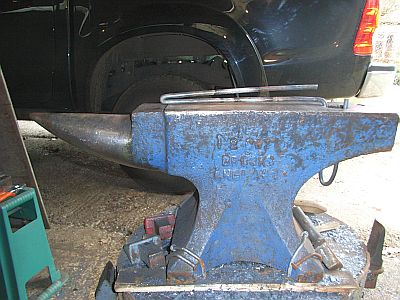
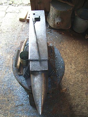
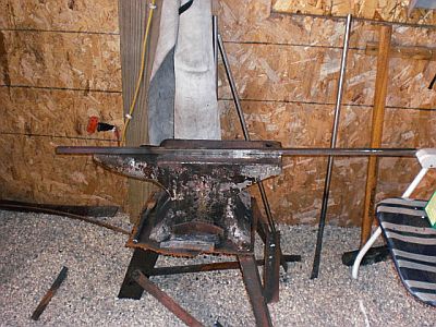
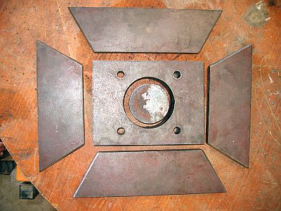
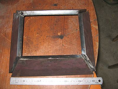
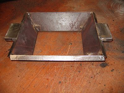
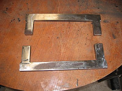
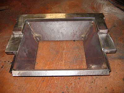
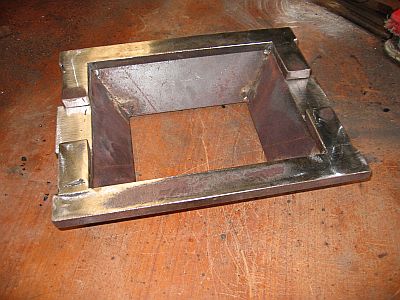
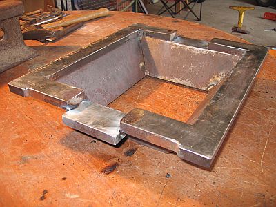
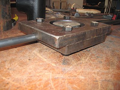
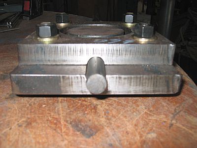
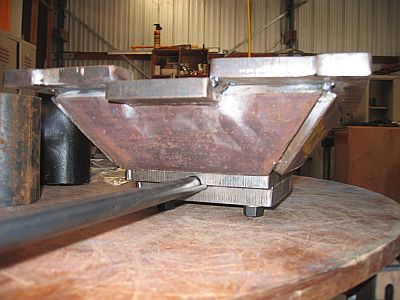
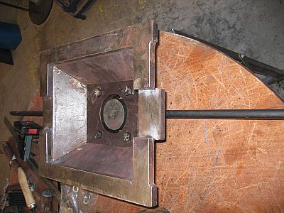
BP0683 Anvil Stand
by Brian Brazeal
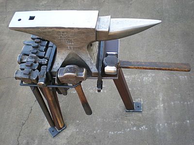
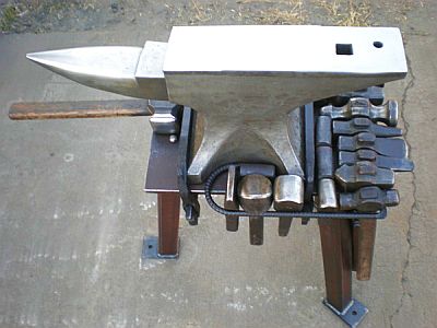
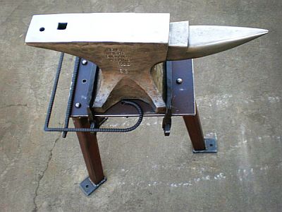
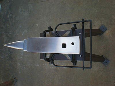
Here's my new traveling anvil and stand. I'll have to make new hardies for its 7/8" hole, and I'll make some hooks to hang more tools. The anvil is mounted like a post vice is mounted with wedges that I forged.
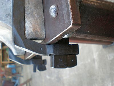
The dimples are just marks to tell me which pieces go together. The two wedge mounts are slightly different in size.
-
IForgeIron Blueprints
Copyright 2002 - 2011 IFORGEIRON, All rights reserved
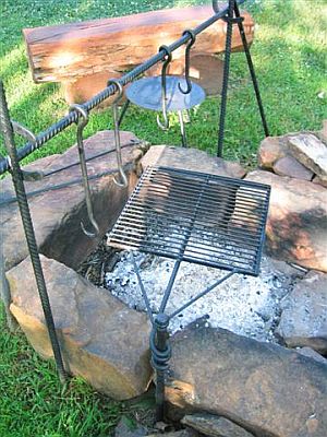
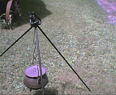
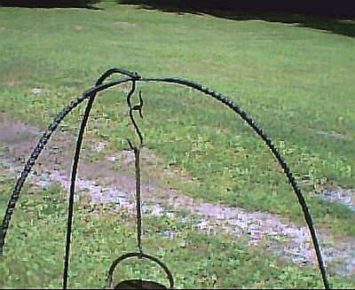
BP0684 Campfire Tripods
by Vance
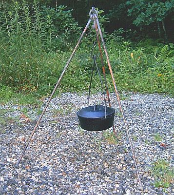
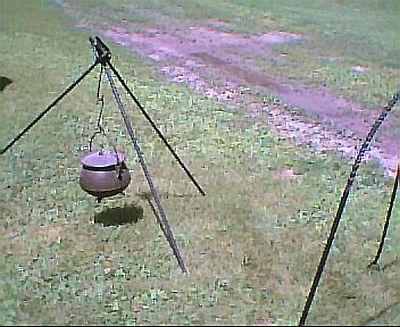
Been wanting to make a nice campfire tripod since I saw this design on one of the forums a few months back.
Since rebar's cheap and plentiful at the scrapyard I figured it'd be good enough for the prototype before I go buy 5/8" HR.
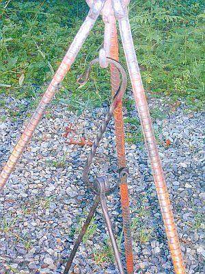
'Course if you're gonna hang a bean pot off the thing you gotta have pot hooks, so I made them, and a fancy twisted S hook to get it close to the fire.
Actually there WERE beans in in the pot, my Texas buddy's recipe for Camp Beans. If I had a fire under 'em you probably could have smelled them. Easy enough to do over the fire, and quick enough to get fed in a hurry.
3 16 oz cans of your favorite beans, pintos, whites, Pork 'n' Beans (no kidney or lima or "baked" beans)
1 cup each, brown sugar, Pace Picante sauce, your favorite BBQ sauce
1 lb of so of ground beef seasoned to you taste with Lawrey's Seasoned Salt -
IForgeIron Blueprints
Copyright 2002 - 2011 IFORGEIRON, All rights reserved
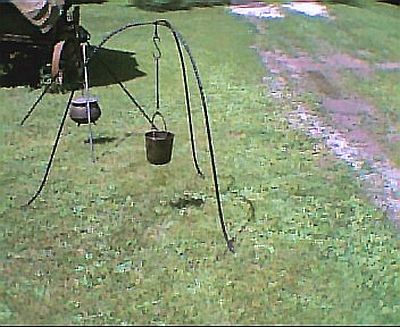
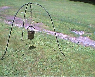
BP0685 Campfire Tripods 2
by Dutchman
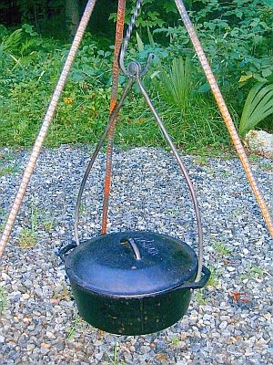
A trammel is good for height adjustment, but a length of chain and s-hooks that fit in the links works fine too.
Your dutch oven is the stove top style. All of mine have three legs, a flat rimmed lid, and already have a bail for campfire cooking.
Here's another campfire idea.
-
IForgeIron Blueprints
Copyright 2002 - 2011 IFORGEIRON, All rights reserved
BP0686 Campfire Tripods 3
by Mike Ameling
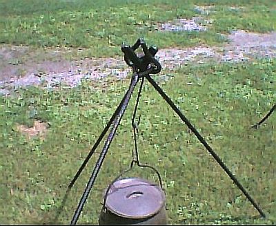
How to do that top of the tripod is always a tricky choice. Most people make an eye loop on each leg, but leave the eye on one open a bit to loop through the other two. Some people use a separate hook or chain to lock all three together. And a lot also depends upon how tall you need it to be. I had to make on a few years go that stood 7 feet tall when set up - to hang their "kettle" from at the right height. And had to use 3/4 square for the strength needed. Their "kettle" held 8 gallons! So each leg of that tripod started out at 10 feet long!!!!! With the eye loop at the end, and 1+ foot stuck in the ground, and spread out around their "firepit", it just turned out right.
Here's a couple picks of a Chuckwagon campfire iron set I made based on pictures of originals from the 1870's to 1890's. It can be set up as a tripod, but usually gets set up as a crossbar with uprights. It is from 5/8's round stock.
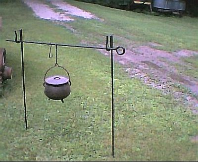
A campfire iron set based on original chuckwagon pictures from the 1870's to 1890's. Made from 5/8 round stock to hold several gallons of coffee and several more of beans and even some hot water for dishes - without sagging.
A campfire iron set based on original chuckwagon pictures from the 1870's to 1890's. Made from 5/8 round stock to hold several gallons of coffee and several more of beans and even some hot water for dishes - without sagging. The round eye on the cross bar locks down around the two upright ends.
And then herer are a couple pics of a Viking era tripod. The original was found on the one burial ship - the Ausberg. It is made from 1/2 square stock. The feet are split into three, and bent out like the claws of a bird. And the twists were done in 6 to 8 inch sections - like the original. A limitation on their forge sizes. One knife maker from Norway that has seen the original in the Museum saw one of these I made a few years ago. He said it looked "... dead on..." compared to the original.
Based on an original from the Augsberg burial ship. The feet are split into three points bent like a bird's claws. The top swivels on a removable hook. The twists were done in 6 to 8 inch long sections - per the original. A person who has seen the original over in the Museum said my copy was "... dead on ...". That was nice to hear.
R-bar can be nice to work with. And occasionally you can find some of the really old stuff. Instead of those lines/ridges formed into it, it has little raised X's down the sides. That little "touch" of decoration really sets your work off. But it is hard to find. I've only found a few feet over the years. Three pieces of 4 foot long that were already made into stakes for tying a rope around, and one twisted up chunk about 8 foot long. The really hard part is keeping my buddies from chopping it up to make fire pokers! One was very upset when I stopped him. He thought it was the PERFECT piece of "scrap iron" to make a 2 foot long fire poker!
But rebar can also give you problems working it. It usually is made from remelted scrap. And so it can contain most any metal alloy in it. A friend once found a whole large ballbearing in a piece - unmelted and not mixed in! He went through two hacksaw blades before he found out why in wouldn't cut!
Nice work Yance. Keep them beans warm, and get that cornbread made! -
IForgeIron Blueprints
Copyright 2002 - 2011 IFORGEIRON, All rights reserved
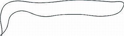
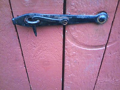
BP0678 Making a Latch
by John King
Start with the proper size flat bar for the size latch you want to make.
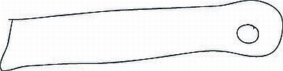
Punch a hole in one end.
Taper the other end and punch a hole in the middle of the bar.
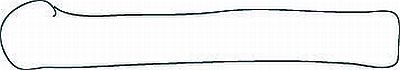
Start with the proper size square or round bar.
Flatten, taper, and bend the hook
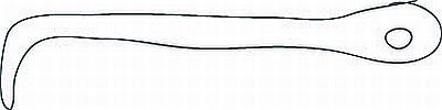
Punch a hole in the end opposite the hook.
-
IForgeIron Blueprints
Copyright 2002 - 2011 IFORGEIRON, All rights reserved
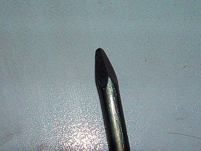
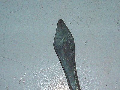
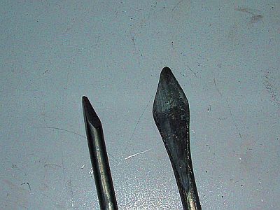
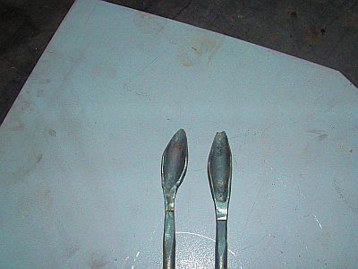
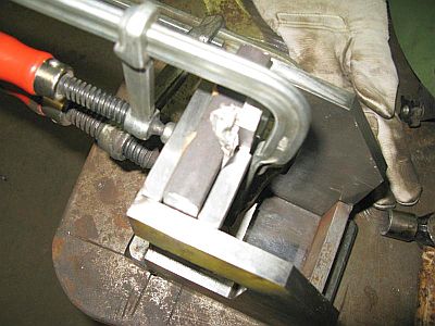
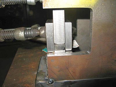
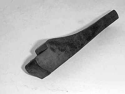
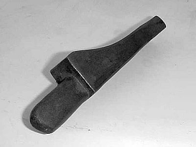
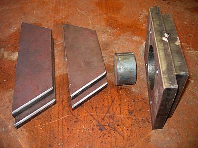
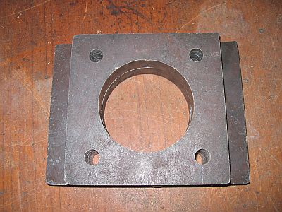
BP0687 Centering Tool for shanks on a chisel
by J Newman
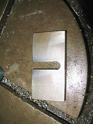
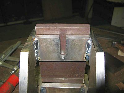
Here is a is a quick and dirty tool I made to center up and square up the shanks to the chisel on these chisels I am making. I don't need the tool for most of the chisels but some of them end up off center or bent at the base of the shank.
The first couple that were out I used my swage with some loose shims to center the chisel on the split line of the swage but after 25lb of swage bouncing off the die I figured I needed a safer way. If I had a huge quantity of these to make I would have made a spring swage with the top and bottom the right thickness but most of the time this tool doesn't leave a flat and if it does it is a very small one. -
IForgeIron Blueprints
Copyright 2002 - 2011 IFORGEIRON, All rights reserved
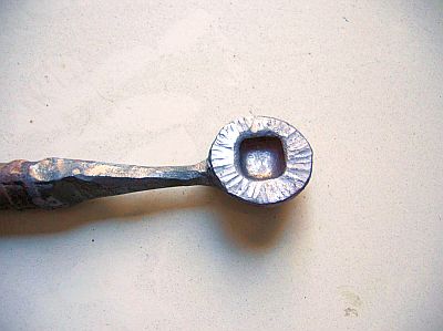
BP0688 Charms
by Nuge
Here's one of mine similar to Brian Brazeal's ring, with a different approach. This technique makes upsetting fun.
3/8 round stock (is that rebar? everyone knows you can't forge rebar. blah blah blah) Take it to the far edge of the anvil and isolate about 1", rotate 90 degrees and then back to your original position. Repeat until you have a thin strand attached to a nice hunk of meat.
Take the strand to round
Bend the meat to 90 degrees as shown
Now the fun part, upset the blob. Don't worry too much about overlaps, concentrate on getting the thin strand to the edge of the mass and not under the lump. This is better visually and things don't get weak. This part is the crux. You need a few off kilter blows until things settle down.
Decorate as you wish
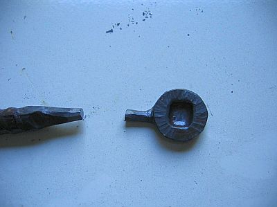
Cut
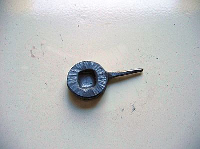
Draw out (Is that rebar? Can't be, I mean thats a pretty delicate operation for junk metal. That taper must be 'bout 1mm or so. (blah blah blah)
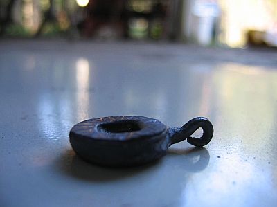
Bend the eye with a needle nose.
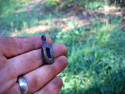
The finished piece, after a little deformation. -
IForgeIron Blueprints
Copyright 2002 - 2011 IFORGEIRON, All rights reserved
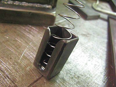
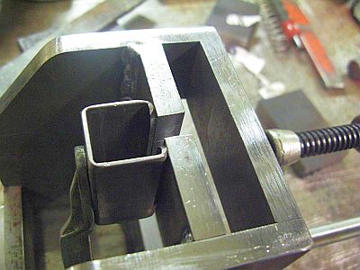
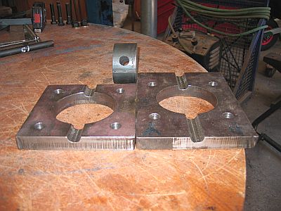
BP0689 Chop saw Modifications
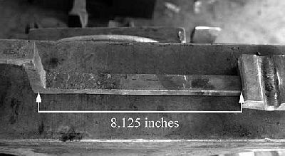
by territorialmillworksHere are a couple photos of a stop gauge I made for our cut-off saw. I used a mill to drill holes on 1/2" centers.
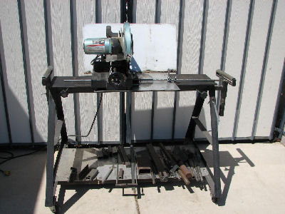
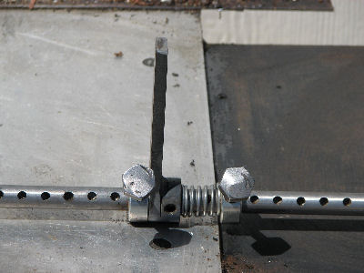
The stop collar on the left engages the detent hole while the stop bar is pinched by the spring and collar to the right. This allows the material to be advanced to the stop bar and then the stop bar is pushed down out of the way before cutting. This lets the cut piece fall free, otherwise it binds against the blade which causes the piece to either flying across the shop or it breaks off teeth on the blade. One is too dangerous and the other too expensive. For 1/4" lengths, I just clamp a small piece of stock to the stop bar.vv
-
IForgeIron Blueprints
Copyright 2002 - 2011 IFORGEIRON, All rights reserved
BP0690 Hawks from hammers
by Stuart WillisGrab an old 24 oz ball peen hammer.
Heat it in the forge and reshape.
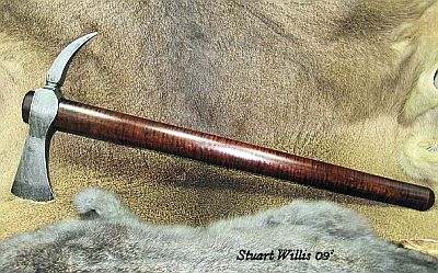
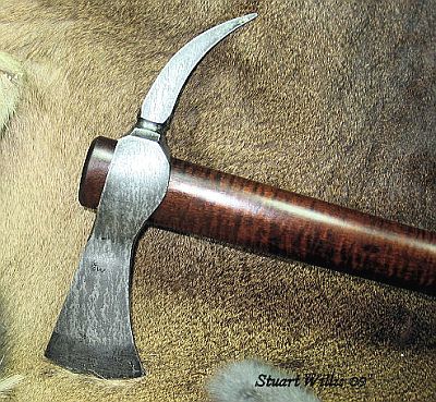
Reforged 24oz ball peen hammer with slightly aged patina and curly maple for the handle.
-
IForgeIron Blueprints
Copyright 2002 - 2011 IFORGEIRON, All rights reserved
BP0691Drawer Pull
by Divermike
Cut flat stock into a square
Example: 3/16th X 2 X 2 grind sides to a rounded edge.
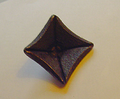
Groove one side corner to corner both directions, with chisel, at least halfway through material. Wider is better i.e. thicker chisel = wider groove.
Heat piece and set in hardy hole or dishing cup
Drive a pyramid punch or Philips screwdriver into center point of groove, this will collapse the grooves and sink the plate into a pyramid shape.
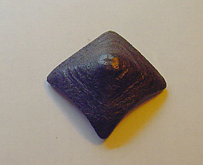
Weld a threaded rod for a drawer pull -
IForgeIron Blueprints
Copyright 2002 - 2011 IFORGEIRON, All rights reserved
BP0692 Winding an Cord, Rope, etc
by Joe (boss)
This is how to wind a cord, rope, hose, or spaghetti noodle without it getting tangled or knotted, provided you don’t already have it wrapped around an old welding wire spool.
I learned it from a CNN video guy. It works for any length of cord out to 250 foot as my experience goes.
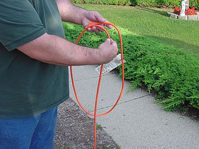
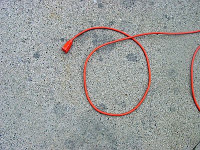
Make your first loop as normal, over the top of the start of the loop.
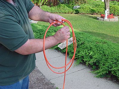
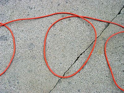
Make your second loop and go under the first when starting the third.
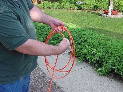
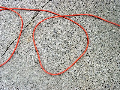
Make your third loop as normal, over the top of the second loop.
Continue in this alternating fashion to the end of the cord.

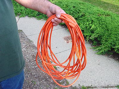
With cords up to 50 foot, you can usually hold the one end and toss it and it will go straight out. Even if it doesn’t go out the full length, you should have no knots or kinks.
It does take practice winding up cords this way, but it is worth learning if you hate knots. -
IForgeIron Blueprints
Copyright 2002 - 2011 IFORGEIRON, All rights reserved
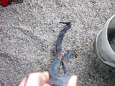
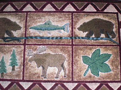
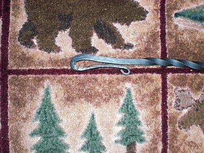
BP0693 Fire Poker
By: John Martin
Note: All appropriate safety gear should be worn while forging. If using a gas forge, like I do, check your lines and the seals. Glasses and ear protection are a must. I am not responsible for you being careless of yourself and hurting yourself or others.
Grab a piece of 1/2" x 36" square stock.
(Please note that you don't have to use that size stock. This blueprint was made using the suggested stock size. It's all relative. You could do this with a piece of 3/8" if you wanted, and it could be shorter or longer.)
Now forge about a 3" long square taper that comes down to about 3/6" at the tip.
Chisel halfway through the bar at the beginning of the taper.
We're going to make a faggot weld so that you have more stock to work and have the hook part made as well. (Sorry if that didn't make much sense, pictures explain it all as we go.) So fold it back on itself and flux.
Bring the end up to welding heat, and weld about 2/5 of what you folded back. (Sorry, that there are any pictures of me forge welding it, didn't have anyone here today to take pictures.)
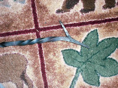
Begin to draw out the end that you forge welded and the hook part.
Now we begin work on the handle. Draw 5" of it out to about 2/5 the original thickness, but keep it 1/2" wide.
Take the end of it and make rats tail.
To make the handle really into a handle, you're going to need to bend the taper back onto the stock somehow. You can use bending forks, you anvil, the horn of the anvil, jig for vise, whatever. I used a jig for the vise.
So, we now have a handle and a poker. Wow, this is a really boring piece of metal, let's add some detail to it.
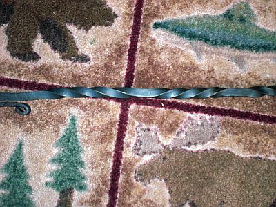
I did four reverse twists done the handle. I measured and make a slight mark with my chisel down the length of it, spacing it out evenly for four uniform twists. Anyhow, you reverse twist down it stopping and starting at the chisel marks.
You can see it those last two pictures how it is all out of shape and warped. There are two ways to fix that without wrecking the sharpness of the twist edges. One, using bending forks, and a jig in the vise, or two use a wooden mallet and a wooden stump. The wood is a lot easier, but I broke my wood mallet. So I have to make another one or a few. And I used the bending forks and what not to straighten it all out.
Anyhow, here is the finished product, ready to help maintain fires!
-
IForgeIron Blueprints
Copyright 2002 - 2011 IFORGEIRON, All rights reserved
BP0694 Decorative grill
by Mark AsperyThe intent of this article is to focus upon some of the problems associated with the grill from the two upset square corners -on out to the blown over, beveled leaf scroll. A detailed description of making and turning the blown over, beveled leaf scroll and the bevelled scroll was printed in the CBA magazines -Issue July/Aug 2004 & Sept/Oct 2005 respectively and is currently on line from the CBA web site under ‘Resources’ and then ‘Projects’ from the drop down menus.
Recently, John West and I conducted some instructor training specific to the CBA level III grill project.
There are a number of issues associated with this part of the grill, the first being the upset square corners and where to place them on the bar and the second being how to connect the water leaf to the scroll.
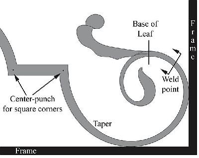
As you can see from the drawing, I have indicated a weld point mid way along the scroll. Also shown is the point where the base of the leaf will start branching from the scroll stock. Utilizing the weld point will allow for the end of the scroll and the water-leaf to be made from the same bar -which is my preferred method of construction with this particular grill. This negates the forming of the leaf from other stock and forge welding it on in an appliqué method.
Using string, I find that the leaf, from base to tip, measures 3 inches long. The scroll from weld-point to scroll tip measures 7 ¼ inches long and from weld-point to the base of the leaf is 1 ¼ inches long.
The variable is the amount of material needed to make the leaf. Having conducted a test, I know that 2 ¾ inches of material will yield a leaf of 3 inches long that fits with the drawing. Change the character of the leaf in the drawing and the stock required changes. I did a very rudimentary article on this subject in the CBA magazine Sept/Oct 2001
Once I have formed the end of the scroll, I can measure down to the weld point (7¼ inches) and then
add the 1 ¼ inches from the weld point to the base of the leaf and then add another 2 ¾ inches for the leaf itself.
I can now cut the bar off at that point and make the water-leaf.
The Leaf / scroll combination will be nicked at the weld point, folded in two and welded from the weld
point back to the base of the leaf as a faggot weld. The cup of the leaf and the bevel of the scroll are on the same
side of the bar, with the chisel nick on the opposite side. The ’blow-over’ to the tip of the leaf has to point in the
same direction as the scroll tip.

I like to make this weld over the bick with my farriers rounding hammer. By welding over the bick with the rounding hammer, I am assured that the transition from the weld to the leaf will be curved, thus helping it read better when finished.
Welding over the bick also allows me to leave a mass of material at the end of the weld that will be used to form the next scarf. The excess material will be needed to form a scarf for the weld onto the remainder of the scroll stock that comes from the upset square corners.
Nick and fold over the leaf and scroll assembly. Weld over the bick
Correct orientation of scarf. This keep the leaf up and the scroll down making a more stable arrangement.
Leaf and scroll tip forgewelded onto the reminder of the scroll stock
The orientation of the scarf is important, as the leaf has to be on the outside of the scroll when finished.
I like to keep the leaf up and the scroll tip stock down on the anvil as I forge weld as it is more stable – so that
gives me the orientation of the scarf on both sides of the weld.
The main body of the scroll tapers from the center-punch mark of the upset square corner on (1/2 by 3/4 inch stock) through the weld point and down to the base of the leaf. The leaf and scroll are to be made from 1/4 by 3/4 stock. I have the thickness of the scroll on the drawing, at the weld point, as 5/16 inch by 3/4 inches.
If I can calculate the amount of material needed to produce this taper from the center-punch mark of the
square corner stock to the weld point, then I save myself the trouble of either -not having enough material or -
having too much and cutting some off to get the correct length of taper to the weld point.
The problem associated with not calculating the amount of stock needed is one of ‘not forging with
certainty’. Rather than forge the end to the required thickness and draw the taper back to the square corner in
one or two heats, the smith is obliged to work sparingly, constantly measuring – with the quality of taper at risk.
There are at least three ways to calculate the area of the taper. I say area instead of volume in this case,
as the 3/4 dimension does not change, so we are only concerned with the change on the 1/2 inch side. This saves
an excess of math work, something for which I am extremely grateful!
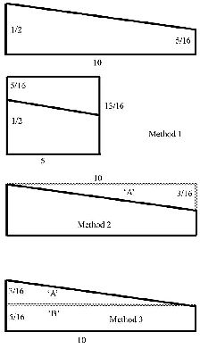
The taper goes from ½ inch wide to ⁵⁄₁₆ wide over 10 inches. Our math possibilities are:
1.) Fold the taper in half to create a rectangle and calculate its area by a Length x Breadth calculation
2.) Calculate the area of the triangle that is not there, shown as ‘A’ in the drawing and subtracting that
number from the area of the rectangle that contains the taper.
3.) Calculate the area of the taper itself by turning it into two objects, a triangle (shown as ‘A’) and a
rectangle (shown as ‘B’ in the last drawing) and then adding the two areas together.
Whichever method is chosen, once the area is calculated, it has to be converted into the length of ½ by ¾ bar needed to make it.
Let’s take method 1
The taper is folded at the half way mark (5 inches) to make a rectangle 13/16 inch tall by 5 inches long.
Area = L x B = 13/16 x 5 = 65/16 or 4 1/16 sq inches.
Method 2
Area of triangle = ½ x base x height = 3/16 x 10 x ½ = 30/32 or 15/16 square inches.
Area of rectangle = L x B = 10 x ½ = 5 sq inches
Area of taper = Area of rectangle minus area of triangle of missing material = 5 – 15/16 = 4 1/16 sq inches
Method 3
Area of triangle contained within the taper added to the rectangle contained within the taper.
Area of triangle = 1/2 x base x height = 1/2 x 3/16 x 10 = 30/32 or 15/16 square inches
Area of rectangle = L x B = 10 x 5/16 = 50/16 or 3 2/16 square inches
Total area of taper = 15/16 + 3 2/16= 4 1/16 square inches.
Calculating the length of bar needed to forge the taper.
This taper has to come out of a bar ½ wide by an unknown length (X) long
X x 1/2 = 4 1/16 square inches
Isolating for X means multiplying both sides by 2 over 1 (2/1)
X x (1/2) x (2/1) = 4 1/16 x 2 = 8 2/16 or 8 1/8 inches long.
A bar 1/2 inch by 3/4 inch by 8 1/8 inches long will yield a taper from 1/2 inch wide down to 5/16 wide over 10 inches maintaining the 3/4 inch dimension.
I like to measure my bar along the center-line so that I don’t have to calculate for the material movement in the upset square corners.
So why all the math? To form the square corners, you may have to grip the bar in the vice and unless you have an adjustable vice jaw insert, the stock has to be parallel sided or it will slip in the vice jaws!
Because of the math, we know to center-punch the ½ inch side of the bar 8 1/8 inches from one end and form the first upset square corner. Once both square corners have been formed, then we can draw the taper from the corner down to the weld point.
One corner can be made in the vice as per the CBA article issue Nov/Dec 2003 or CBA web site under resources then projects. The second corner, due to its close proximity to the first, will probably have to be made at the anvil or at the anvil and vice combined, but not totally at the vice unless you have a vice with small jaws and can hold the stock vertically between the jaws without fouling the lower corner or leg.
To negate the use of tongs when forging the square corners, I like to use a long bar of the required stock size so that I can split it in the middle with a pair of square corners on either end. There are 4 sets of square corners on the grill. The bar will, of course, have to forge welded back together again at some point. I find it easier to do this than to deal with turning the bevelled scroll over the bick with a very long bar attached.
To determine the length of the original bar, the amount of stock needed to create the taper to the weld in the middle of the grill will have to be known. This is just a repeat of the same sort of math we did earlier.
Use a bottom swage to prevent the stock from creeping along the anvil as your form the upper square corner.
The corners are 2 ¼ inches apart -center to center and the center of the bar does not change length along the centerline
when forming upset square corners.
If you choose to use the long bar for your own square corners, completing the corner nearest to the bevelled leaf scroll first will be helpful to you. To prevent the end of the bar from slipping away as you form the square corner on the anvil, use a bottom swage in the hardy as a stop for the end of the bar.
Forming the corner by hitting directly down onto the anvil face is a very strong move and one that can over penetrate the corner and upset the bar below it. To prevent this over-penetration, quench the bar up to the bottom of the upset square corner prior to working on the anvil.
Once you have completed both square corners, you can now turn your attention to the taper. You know that you have an exact amount of material to form the taper. You also know that the end of the taper will be forge welded to the leaf and scroll tip assembly.
During the forge-weld, the taper material may be thinned somewhat. To prevent the taper from being overly thinned, draw the end of the proposed taper down to 3/8 inch thick and form a scarf to the end for a lap weld.
Once you have made and drawn down your weld, then the taper can be refined. By initially drawing the taper out to 3/8 inch thick, it will be too short. This is insurance for me. I know that the position of the leaf on the scroll is somewhat exact and won’t stand much movement. It will be easy for me to stretch the taper and get the leaf in the right position. It is much harder to shrink the taper!
I can draw out the taper until I get the base of the leaf exactly where I want it in terms of length from the center-punch of the upset square corner. The tip of the scroll can vary a little and not affect the look of the overall piece too much, not so with the leaf. -
IForgeIron Blueprints
Copyright 2002 - 2011 IFORGEIRON, All rights reserved
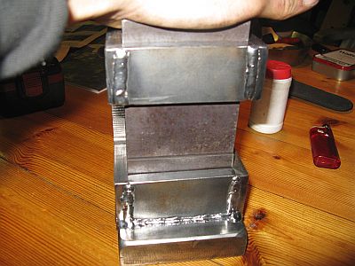
BP0695 Guillotine Tool
by DCL
I have been wanting and needing a Guillotine tool for a long time and decided I wanted to make it my self and do a "how to" while I made it.
This tool is used instead of a top and bottom tool for the hardy hole and is also a kind of spring fuller and can be used in knife making, sword making and general blacksmithing. It is the blacksmiths 3th. hand and allows you to make fullers and other thing and still work alone and not need help to do some things I find that very good since I most of the time work alone and with no one to help me.
I hope this helps some one to make one for them self and maybe improve the design.
First before doing any of this make sure you use the right safety equipment while working, all tools and power tool are dangerous to use if used in a wrong way and you follow this How to on your own risk and all responsibility is your own. Stay safe.
Needed tools:
a hacksaw
metal file
clamps
welder (MIG, ARC or TIG I used MIG for this)
6 and 8mm metal drills and a drilling machine
small hammer and a rule
Nice to have:
drill press
angle grinder grinding and cutting disks
Steel needed
I have used 10mm mild steel plate to make the main body from, any thing can be used I recommend using something a bit thick as it will make it more stable.
Here is a pic of the pieces
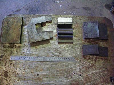
The sides are cut on a band saw and milled out in side the "C".
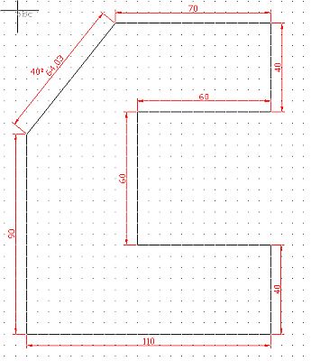
The drawing I made in autocad for the project
The two side pieces showed above can also be cut out with a anglegrinder.
6 pieces of 40x80mm for spacers between the sides.
A piece of 25x100x150 for the bottom it is important that this is made of some thing thick and heavy since this is the part that takes all of the impact from the hits.
A piece of 25mm square pipe 45mm long to hold the spring
A piece of 6mm round 25mm long for the bottom of the square pipe so the spring don't fall out
Another piece of 6mm round 52mm long for inserting in the top tool and over the spring so it can lift the tool up after a hit. (I used stainless 316 as I had that in 6mm but any thing will do.)
Steel for the tools I made from 5160 spring steel it is not important that it is a hardnable steel if you only are going to use it for hot metal, but I like to harden mine. the top pieces is 15x79x100mm
The bottom part 15x79x55mm. They are only 79m wide so that they have a loose fit and do not jam.
A spring that will fit inside that square pipe that is just so strong that it will lift the top tool but not throw it out of the Guillotine.
It is important to clamp the pieces together before welding it. I use a small hammer for lightly hitting the pieces in the right place after clamping it in place so that the sides are 100% even. When you weld it up remember to follow the same order to do so that I show here or you might end up trapping in some sides and get a hard time reaching them latter on.
Here are some pics and I'll explain along the way. Before welding any thing up, it is important to put a spacer between the sides in the top so that they do not get bent or twisted when welding in the bottom.
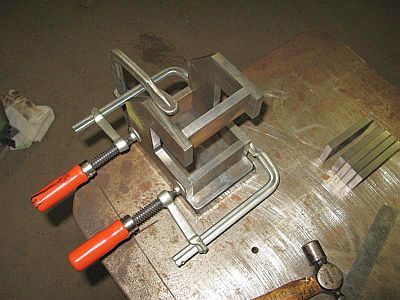
Here are the sides and some spacers clamped up to get the right width between the sides when I weld em to the thick bottom plate.
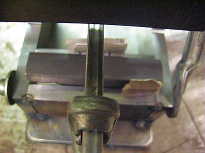
Clamp up the two spacers on each side of the bottom tool and put in some cardboard or folded paper to get a loose fit when changing the tools.
Then welded in the spacer in the back.
I clamped up the top spacers with the top tool, and some cardboard between, to also get a loose fit here.
I also clamped the tool together to get em to hit.
Weld up the from spacer and take out the spacer behind the tool "Dies" and drill a 8mm hole 14mm from the bottom of the plate and in the centre from the sides and with a hack saw cut out a groove and file a bit to make it even. This is for the 6mm round in the top tool "dies" to top of the spring.
Clamp it all up as before with cardboard and weld it up.
Take the 45mm long square pipe and to the same thing to also make a groove in one of the sides.
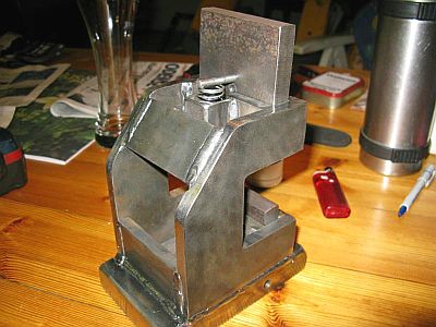
Weld the 25mm long 6mm piece in the middle on the bottom end of the square pipe it can also be a thin plate piece but a round stick is better since it will allow dust scale and such to fall down and not "cluck" the spring so it wont work. Here is it with the spring inside.
I clamped it the the inside of the spacer in the top and make sure the two grooves "holes" are aligned with each other so the stick can slide in it easily. Then weld it up.
Then in the top tool "dies", in the middle from the sides and 55mm from the bottom, I drilled a 6mm hole and put in the 45mm long round 6mm piece in place.
Then I welded in the last piece on the back shown here.
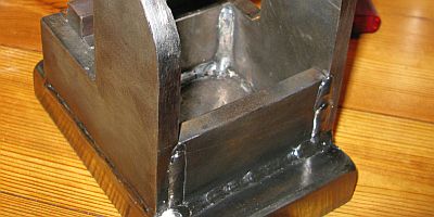
Then we are done you can grind the welds away if you don't want them or let them be, I let them be I think they look cool and I will have it painted when I get some paint so that it don't rust.
Drill some holes in the bottom plate and mount it on a stump as I will do when I get the time or weld on piece of square stock so that it can fit in the hardy hole of a piece of plate so that it can be clamped it a vice.
Here are pics of it done
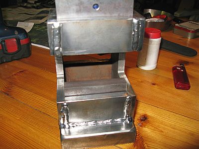
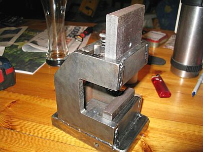
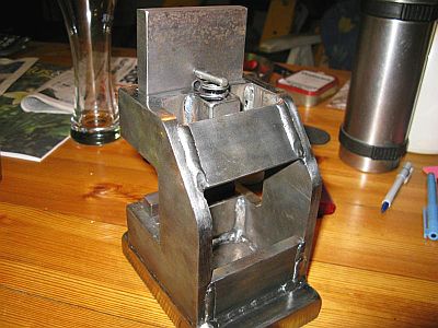
The tools "dies" top and bottom can be changed and many of them made in different shapes for different jobs I use a set of half round and set of square and will get one made for cutting and with the bottom tool "dies" made of copper or brass.
Regards Daniel CL (DC) -
IForgeIron Blueprints
Copyright 2002 - 2011 IFORGEIRON, All rights reserved
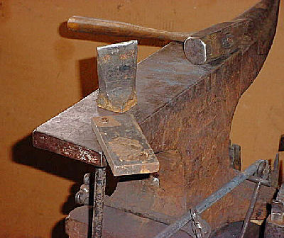
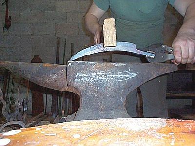
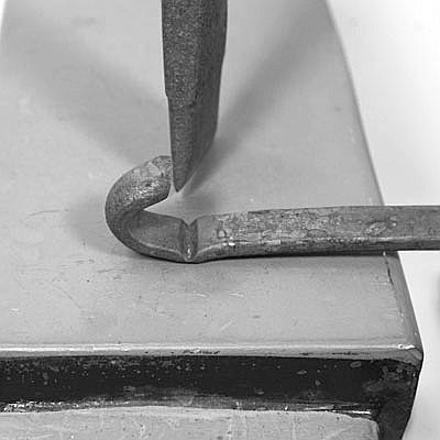
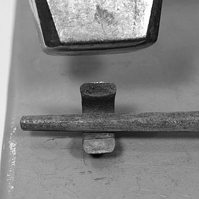
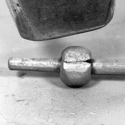
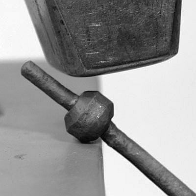
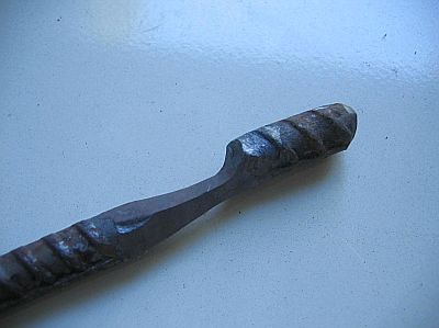
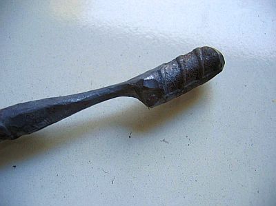
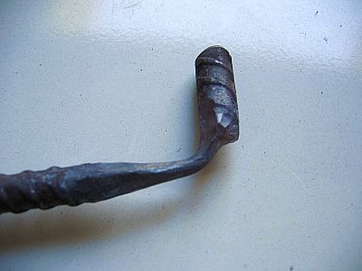
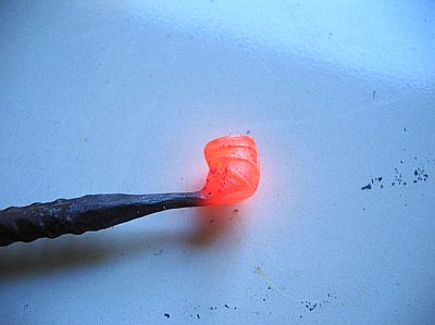
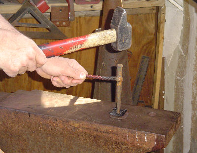
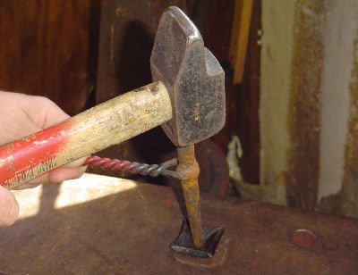
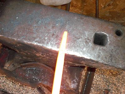
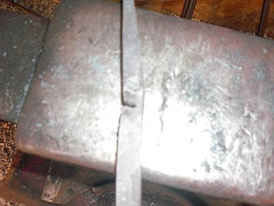
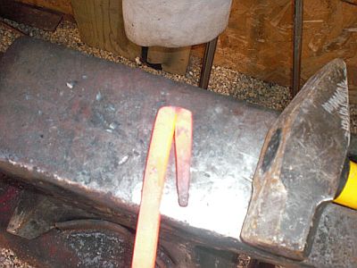
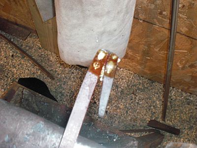
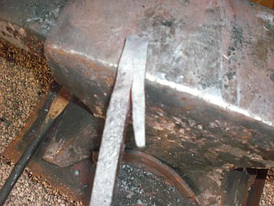
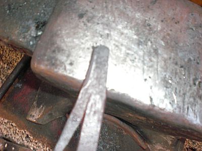
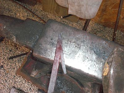
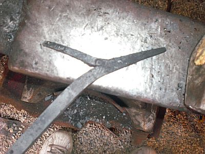
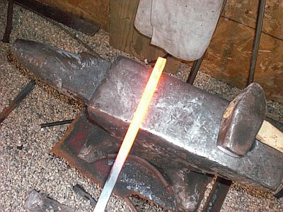
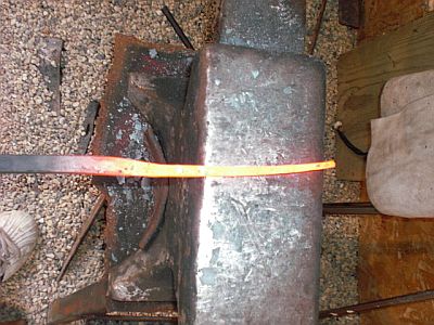
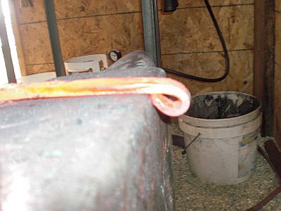
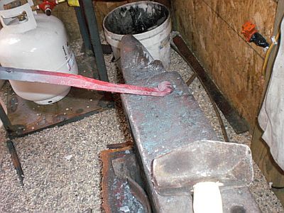
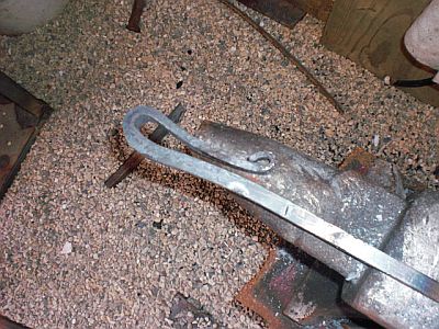
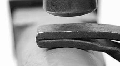
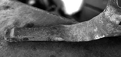
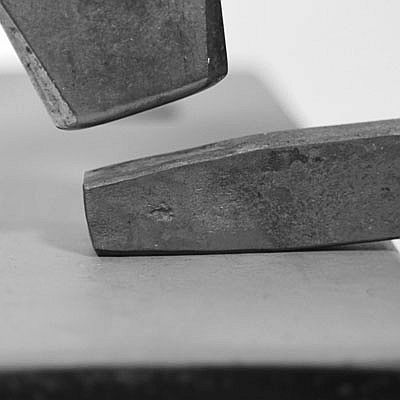
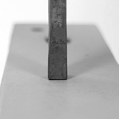
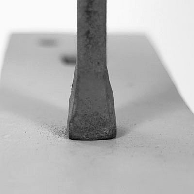
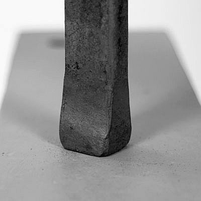
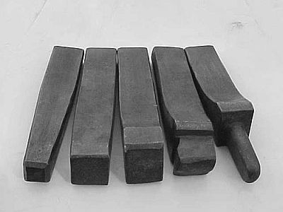
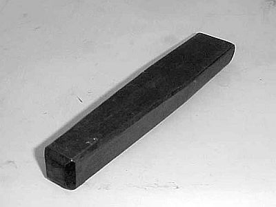
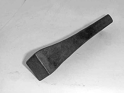
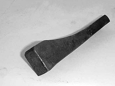
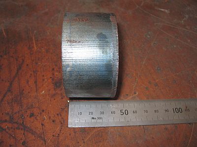
BP0696 Hardie tools
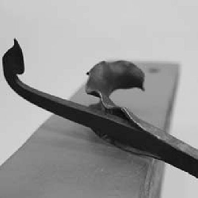
by Mark Aspery
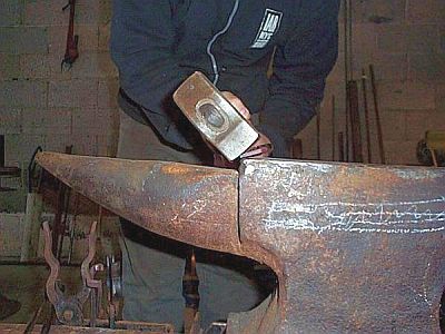
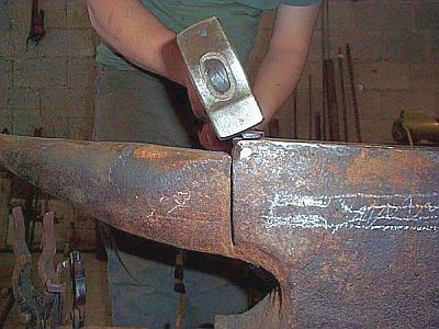
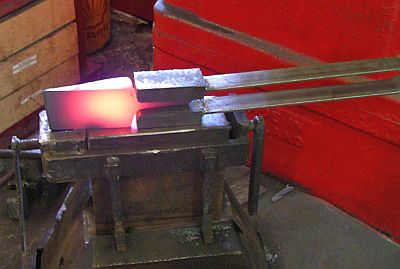
A friend and I were making some hardy tools from Jack hammer bit today.
The upset collar of the jack hammer bit did not sit flush on the anvil surface.
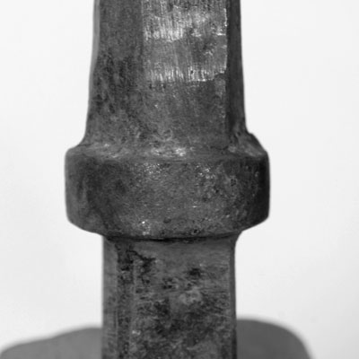
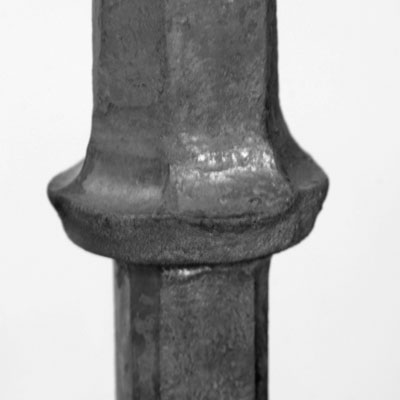
We used a fuller to forge down the collar and get a better - more stable - fit of the tool in the hardy. -
IForgeIron Blueprints
Copyright 2002 - 2011 IFORGEIRON, All rights reserved
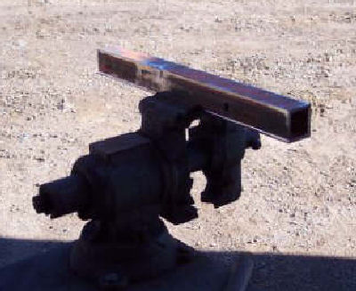
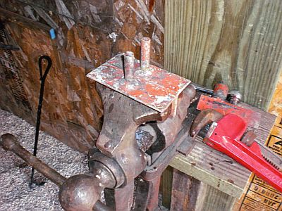
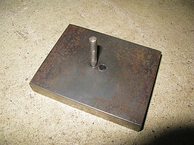
BP0697 Hold Down Tool
by james gonzalez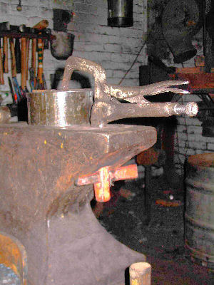
I am using it here to hold a piece of pipe down.
Here's a handy anvil hold down I made out of an old visegrip.
-
IForgeIron Blueprints
Copyright 2002 - 2011 IFORGEIRON, All rights reserved
BP0680 Upsetting - stabilizing the bar end.
by Mark Aspery
The end of a bar can be stabilized somewhat, prior to upsetting, by drawing a two sided taper to its end. This will increase the dimension in the other plane (usually the thickness).
I have shown this twice below, once with a short upset and again with a longer upset for a heel tenon.
The taper allows the bar to upset without having to correct far a growth in width during upsetting as well as helping the bar resist the urge to bend and warp during the upset.
The first progression shows the finished upset where no blows on the side were needed save for a little chamfering. This can be quite useful to a smith as it can prevent the local upset of the sides (causing the lipping and cupping) that can be associated with corrections at the end of a heat on a large bar.
The bar is 1 inch by 1/2 inch.
The heel tenon bar is 1-1/4 inches by 5/8 inches.
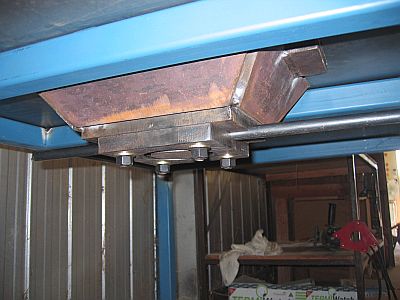
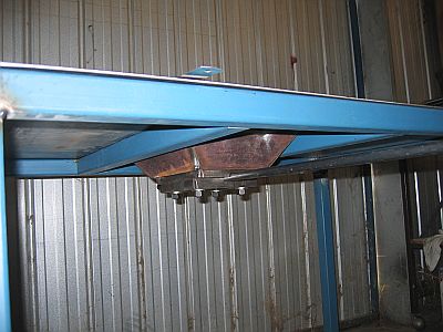
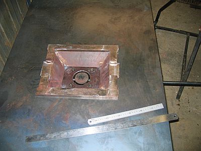
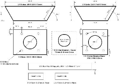
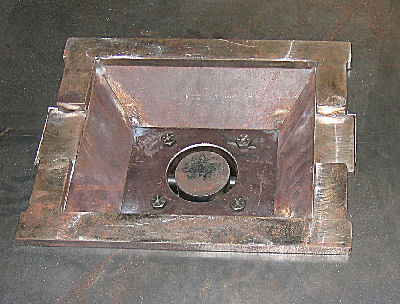
BP0672 Building a Fire Pot
in BP 600 Series
Posted
IForgeIron Blueprints

Copyright 2002 - 2011 IFORGEIRON, All rights reserved
BP0672 Building a Fire Pot
by Darren O'Loughlin