

Steve Sells
-
Posts
9,162 -
Joined
-
Last visited
Content Type
Profiles
Forums
Articles
Gallery
Downloads
Events
Posts posted by Steve Sells
-
-
IForgeIron Blueprints
Copyright 2002 - 2011 IFORGEIRON, All rights reserved
BP0442 Metal Cooler
by Glenn Conner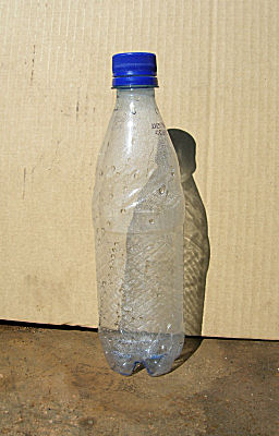
You can use a water bottle with a recloseable sports cap, or just drill a hole in the cap.
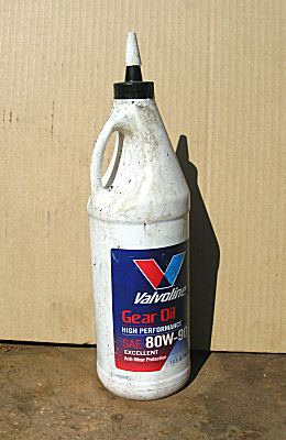
But a gear lube bottle already comes with a funnel cap.
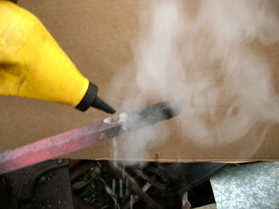
Just fill the bottle with water. The funnel cap will direct a small stream of water on to the hot metal to create localized cooling.
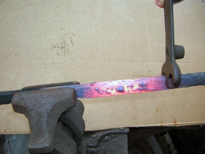
This will isolate the heat to where you want it, as when you are making a twist.
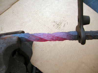
Now you can control where the twist starts and stops.
-
IForgeIron Blueprints
Copyright 2002 - 2011 IFORGEIRON, All rights reserved
BP0444 Cold Forming Armor or a Bowl
by Glenn ConnerThis same procedure is used to form armor, but for this Blueprint we will use a bowl as the subject.
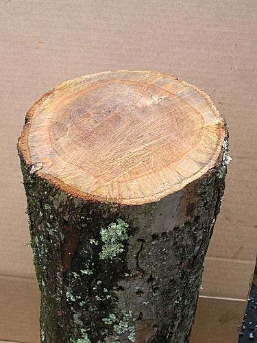
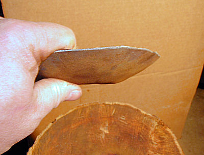
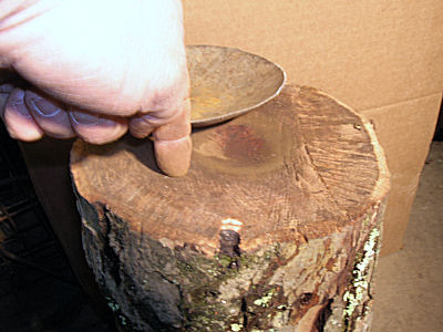
Start by making a "wooden" swage. This is a 8" diameter piece of firewood.
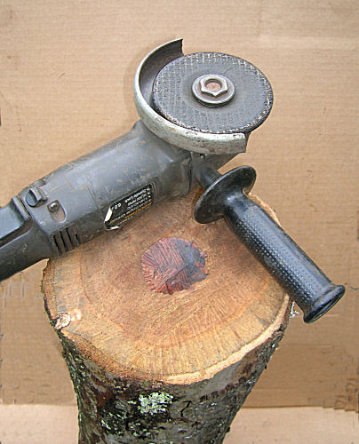
Make a shallow depression.
A 4-1/2" grinder was used only because it was handy.
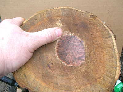
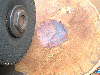
The depression is little larger than an egg and maybe 3/8" deep.
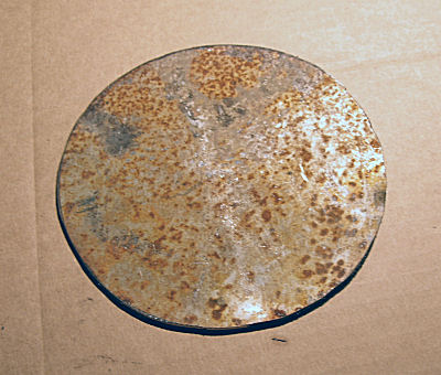
The metal for this blueprint is a disk cut from the lid of a 55 gallon drum.
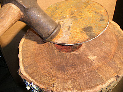
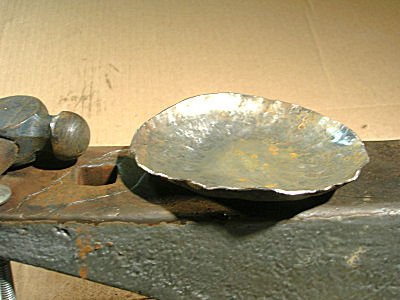
Place the metal over the depression. Starting at the outside edge work all the way around and gradually work your way to the center, working all the way around each time. Work with blows just hard enough to stretch the metal gradually and avoiding kinking or making big dings.
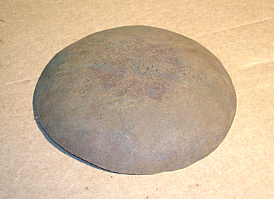
After a couple of passes, the metal starts taking the shape of a bowl.
You can see the sides of the bowl. The bottom is still flat.
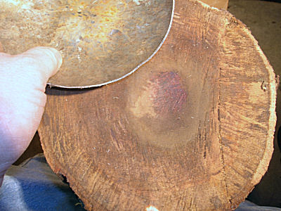
The scuffing shows how the depression works and where the metal is in contact with the wood.
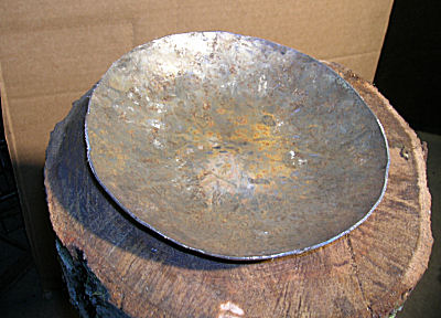
After a couple of passes the edge raises up about a finger joint and a half.
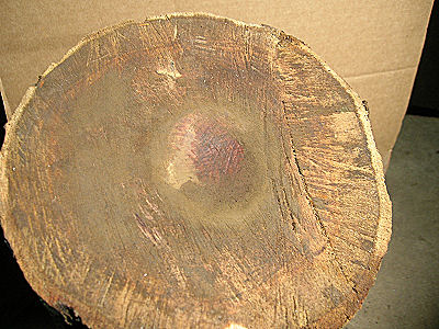
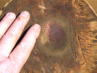
A close up of the depression shows that the metal never touched the bottom of the depression, Only the edges were used as a support and the hole was used as an unsupported area for forming the metal.
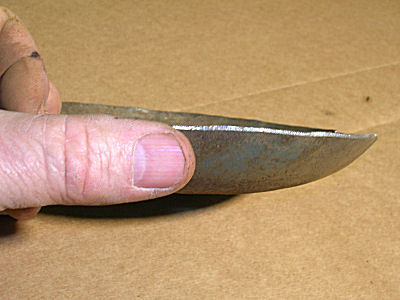
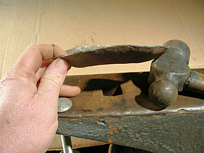
The side of the bowl after only a few passes.
The bottom of the bowl is still flat.
The side is still over a finger joint tall.
The bowl is no where near finished. This was only a few passes with the hammer to show how a slight depression in wood could be used to form a bowl. This is not the only way to accomplish the task, just one way.
-
IForgeIron Blueprints
Copyright 2002 - 2011 IFORGEIRON, All rights reserved
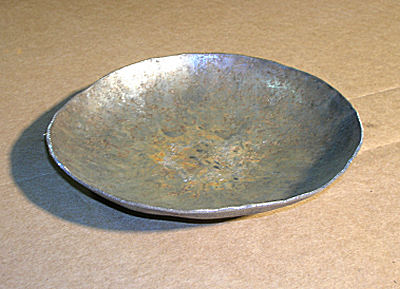
BP0445 Cold Forming Armor or a Bowl 2
by Glenn ConnerWhat you make is your choice, the purpose of this Blueprint is to show you one way it can be done.
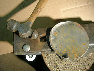
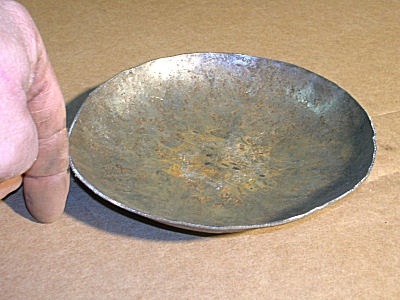
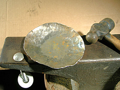
All you need is a hammer and an anvil to make a bowl. The round blank has shows the results of the first pass.
The anvil buried in sand, and the carriage bolt and washer dampen the ring of the anvil.
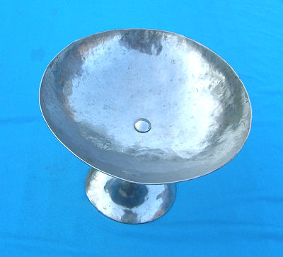
After a couple of circles you can see the bowl taking shape.
The impact marks show the part of the anvil being used. The metal is supported by the edges of the hardie hole, and the hammer sinks or pushes the metal into the hardie hole a little bit with each hammer blow. The wear pattern tells the story.
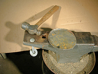
Work from the outside toward the inside and in a circular pattern. Try to get close to the finished product as you work your way across the metal.
A couple more passes and the bowl is a little deeper and the sides are more refined. Notice the bottom is still flat.
The wear pattern on the anvil is still the same.
It is a good start, just needs a little more work.
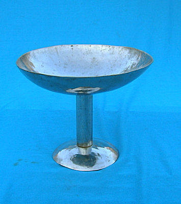
Getting things to this stage took almost as long as cutting out the circle of stock. From here you keep working the metal to bring it to the shape you desire. It will have a nice "hammered" look. To get a smooth texture, you planish the metal, file the metal, sand the metal, buff and polish the metal.
Planish is to give a smooth finish to (metal) by striking lightly with a smoothly faced hammer or die. This is usually a term used by auto-body workers, and armorers.
-
IForgeIron Blueprints
Copyright 2002 - 2011 IFORGEIRON, All rights reserved
BP0446 Using Your Anvil
by Glenn Conner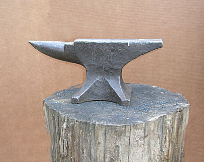
Many times when someone says anvil, you only see it one way. It sits on a stump, or anvil stand, and it looks much like all the other anvils you have seen. It is a nice looking anvil !
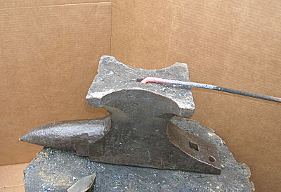
No one said you could not put it face down and use the base as work surface.
Or use the handling hole as a hardie hole.
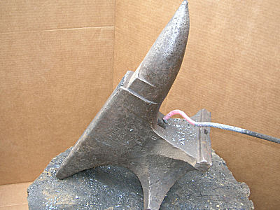
Those things can be surprisingly deep.
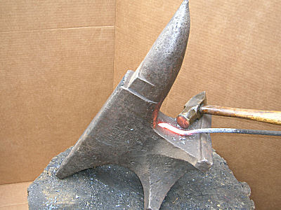
But then you have the curves of the anvil that can be used to make curves of one size.
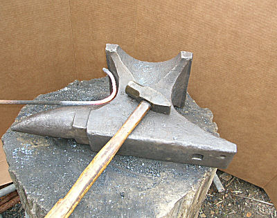
The other side of the anvil had a different shape and produced a sifferent size curve.
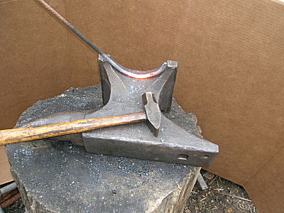
The foot has yet another shape and produces yet another size curve.
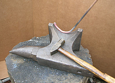
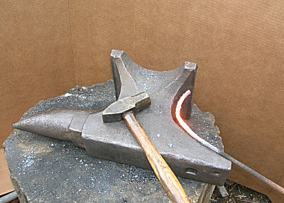
And don't forget to try things in both directions. There may be a difference.
A small anvil can be turned in many different ways and many of the surfaces can be used. You paid for the whole anvil, why not use the whole anvil.
-
IForgeIron Blueprints
Copyright 2002 - 2011 IFORGEIRON, All rights reserved
BP0448 Derusting Metal
by Glenn Conner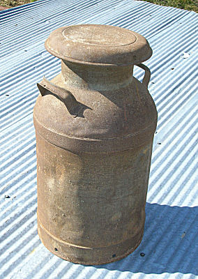
Never tell your wife your cleaning out your smithy. For years, I have used a couple of old metal cream cans with some boards across the top as a shelf in the shop. Once the cream can containers surfaced, they were declared an endangered species and MUST be cleaned up. (Read that as "wife speak" for cleaned, painted, and moved to a location of her choice.)
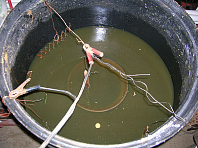
Use a plastic container.
Make sure that the battery charger and electrical cords can not come in contact with water.
1 tablespoon of Arm & Hammer Super WASHING soda (sodium carbonate) per gallon of water is a good mix for this process. Baking soda (sodium bicarbonate) can be used, but it takes a lot more sodium bicarbonate than sodium carbonate.
The hook up is rather simple, use a battery charger and connect the NEGATIVE to the material you want de-rusted, and connect the POSITIVE to where you want the rust to go. In the photo the negative connection is down the side of the container to the cream can, and the positive is to 3 pieces of scrap metal, one on each side and one in the middle of the cream can. If the object has multiple parts that may not be electricly connected, multiple connections should be used for best electrolytic performence. You may need to wire brush or otherwise remove the rust to bare metal to get the best electrical connection.
DO NOT use stainless for the electrodes as they make some very nasty Hexavent Chromium that is poisonous, is absorbed through your skin, and is a haz-mat material.. Any rusty piece of iron will work just fine.
The positive metal must NOT touch the metal being de-rusted. Only 2 to 4 amps is needed. If you exceed 4 amps, remove some of the positive metal from the water. Give the process some time.
I don't get worried about the rust that forms on the surface as the item dries, I just let it form, and then treat with Phosphoric acid solution. After it drys, you have a nice chemicly bonded layer of Iron Phosphate, (FeO3) witch acts as an impervious coating to future rusting, and is an excellent enamel primer.
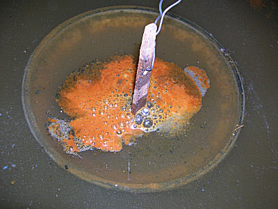
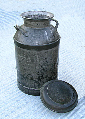
The process will produce bubbles and breaks some nasty rust and crude loose. In this case a piece of positive scrap metal was hung in the center of the cream can to remove the rust on the inside of the container also. Pull the positive scrap metal out of the water a couple times a day and clean the rust from the metal.
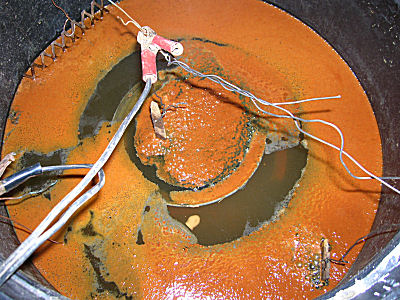
Did I mention it can get nasty? From everything I have read, the process is self limiting, and will not hurt the original base metal.
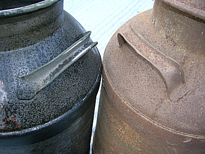
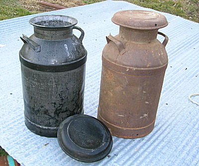
After 2-1/2 days, the cream can was removed and a pressure washer was used to clean it up. As the metal is now clean and wet, it can flash rust. Have your paint brush (or spray can of paint) handy and apply a protective coating as soon as possible.
Now where is that can of paint.
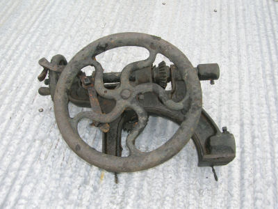
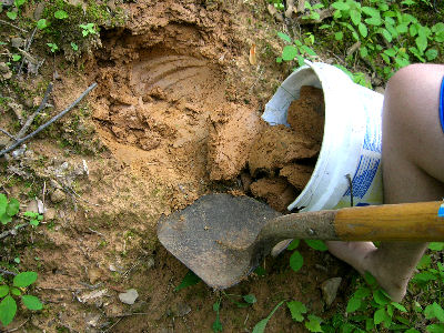
Sometimes when you ask people to look for scrap steel you get some interesting things. The fellow said the last floods had washed the dirt away from some gears in the creek. He pulled them out of the mud with his truck and ask if I wanted them.
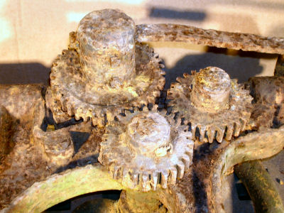
The gears were encased in mud. A full pressure washing was needed to even get down to the rust.
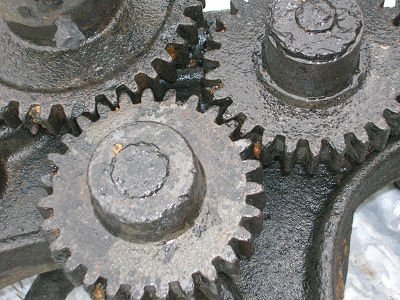
And there was some rust.
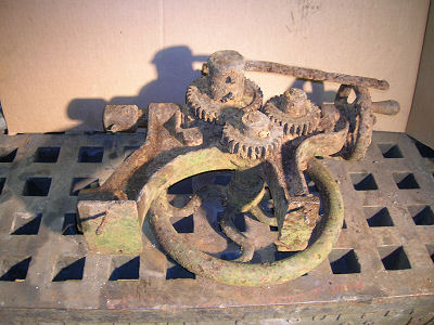
After the mud was removed, it was time to clean it up a bit more.
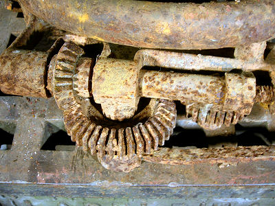
The whole unit was derusting using the technique in this blueprint.
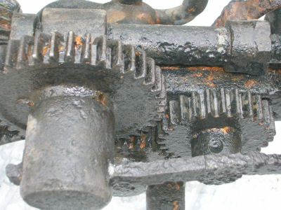
The gears did clean up nicely.
Derusting does not fix broken parts or make things new again. It does remove rust from metal. Now for a little TLC (Tender Loving Care) to salvage the parts for use on other drills.
-
IForgeIron Blueprints
Copyright 2002 - 2011 IFORGEIRON, All rights reserved
BP0449 Lathe Maintenance
by Irnsrgn
Just a few noteworthy items on lathes or any machine tool with ways.
A lot of people worry about being able to operate a lathe or other precision machine tool in a manner that will be consistent to produce a fine finish to a given tolerance. Many think that learning to operate it efficiently is all you need to know.
For any precision tool to operate with precision and to maintain that precision over time it must be MAINTAINED PROPERLY, just like an automobile. It needs to be lubricated at regular intervals with the proper lubricants, to be cleaned to protect its finish and its tires and spark plugs need to be changed when worn or damaged.
Most older lathes and precision machines do not have roller bearings in them but rather use either brass or babbit bearings which if kept properly lubricated will wear very little over the life span of the machine. Ball bearings in precision machines are not your normal off the shelf industrial bearing, but precision bearings made especially for precision machines, and must also be maintained to keep their precision.
For most things where a brass or babbit bearing is used, a .003 clearance is needed for an oil fit, and .005 for a grease fit. to allow the lubricant to coat the surfaces and do their job. Because of the close tolerance that must be maintained with a precision machine tool, these lubrication tolerances must me less in a machine tool to maintain its precision. This can make the bearings heat up quicker and also wear much faster if not lubricated at frequent intervals with a proper lubricant. In my years in the field of smithing, welding and machining, and visits to different shops I have seen many different opinions and many different lubricants used to maintain these precision machines.
Roller bearings are the easiest to maintain as there are recommended lubricants for use with them.
Brass and Babbit one the other hand require a totally different approach and lubricants. The lubricating medium that has shown the most useful for the headstock bearings (the part that rotates the chuck), in my opinion is a mixture of 8 parts 10W non detergent motor oil and 2 parts of a product called Slick 50, that was originally designed as an additive for airplane engines. A normal lubrication schedule is an application before use and every two hours of use. With a constant vigal of the bearings by feel for heat build up. Heat build up will make the spindle expand in size, and create friction and heat from especially high speed use. The bearing is in a more or less massive housing that will limit the expansion of the bearing, then the combination of friction and heat will decrease the area for the lubricant to flow and may end up galling and seizing the spindle and bearing together.
The most important part of a lathe or other precision machine tool is its WAYS, the highly precision machined and ground runners that the Apron (the part that moves back and forth) move on. Once these are damaged or worn precision just went out the window so to speak. Older machinists or those who have been long time machinists can often still maintain precision cuts by knowing how to position the cutting tool in the proper location to compensate for this wear. Thur the years the best lubricating medium I have come across other than WAY BED OIL is a mixture of 9 parts hydraulic oil and 1 part Marvel Mystery Oil. Hydraulic oil has anti corrosion additives and is made to lubricate the very small tolerances that are necessary in hydraulic pumps and motors. A normal lubrication schedule is to clean the ways before use and apply a light coat of lubricant before use.
THE WORST ENEMY of a lathe is DUST. As you know it is in the air all the time and has a tendency to settle on everything. When it settles on the oily ways of a lathe it mixes with the oil and if not cleaned off completely it forms an abrasive compound that will destroy the precision of the ways.
NEVER use gasoline to clean any bearing surface as it leaves behind an unseen residue that breaks up the film of oil necessary to lubricate. Mineral spirits is a good cleaner and easily obtained.
The best way to prevent dust from building up on precision machines is to COVER them with a COTTON BED SHEET. It will breath, thus preventing any moisture build up under it such as would happen with a plastic cover or tarp, moisture is in the air all the time and it rises with the air from below and if trapped under the cover will condense on the lathe parts and quickly rust the exposed parts.
Another important maintenance item is keeping the cuttings cleaned up so they don't get forced under the Apron as it traverses toward the chuck. A paint brush is good for this. I use air pressure to blow the shaving away, but the old timers would frown on this procedure. If you do use air pressure make sure not to blow the shavings into the gears of the lathe as it may cause the gears to shear teeth and cause excess wear. I make simple sheet metal pans to prevent a build up of cuttings.
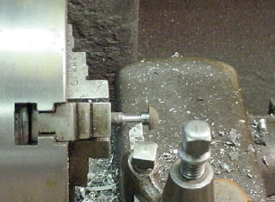
As most lathe work is close to the chuck, this is the area of greatest wear to the ways on a lathe.

9 inch SB tray.
Old 18 inch tray.
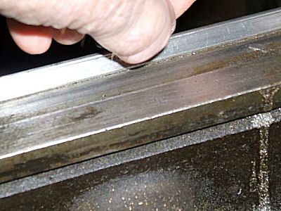
To quickly check the amount of wear on a lathe you are looking at, just use your fingernail on the inside of the way nearest close to the headstock as this is where the most wear will be. You can determine the amount of wear by the ridge near the top of the way as shown below. You can see it from the backside in this picture. Although this lathe has seen some use and a little lack of maintenance it can still do the work by careful setting of the tool point.

The easiest way to set the tool height for a lathe is to use a 6 inch steel rule with the lathe tool point tight against the work and rule so that it doesn't slip down and adjust the point so that the rule is up and down as shown below.
If you take a small cut over the whole length of the piece and then measure the ends and it is not cutting true, their can be several things wrong. First check the tail stock to be sure the tail stock is lined up with the headstock if you are turning between centers (it is adjustable side to side). If its due to wear, and its larger at the chuck end, the lathe apron is either dropping or moving toward you because of wear in the ways. Move the tool bit a little higher to compensate. If it is smaller move the tool point down a little to compensate, then take another small cut to check it. Remember it doesn't take much up and down movement to make a big difference in the outcome of the cut.
-
IForgeIron Blueprints
Copyright 2002 - 2011 IFORGEIRON, All rights reserved
BP0450 Clean Coal
by Glenn ConnerWhat if you stored your coal in a metal bucket. And when you moved it to the forge, the bottom had rusted out, and now you have coal scattered on the ground. Not to worry.

Collect all the coal, sticks, rocks, sand and whatever else you get when you rake it up. Now you have some "dirty" coal. Not to worry. Just pick out the big stuff, the plastic film, the big rocks and pieces of metal, etc.
Now this would be a nasty mix to put into a forge. More than likely the rocks would explode from the heat, and the rest would produce a monster clinker. You need to separate the good coal from the rest of the junk.

Just throw it all into a bucket.
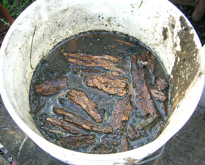
Add water. The wood will float to the surface and the rocks will sink to the bottom.
Now comes the fun part, reach in and collect the wood. Then reach in and stir the stuff in the bottom. It works better to keep a good bit of water in the bucket during this process.
The coal, being less dense than the rocks, will separate and form a layer on top of the heavier rocks. With a little practice you can stir the mix and grab hand fulls of the coal with very little or no rocks.
Now you have the sticks in one pile, the coal in another, and the rocks in a third. Throw the rocks back on the ground and keep the rest.

Use the sticks to help start your next fire. Why throw away good fire starting materials.

Add the now "clean coal" to the fire once the sticks start to catch fire.

No use spending your time trying to pick the pieces of coal out of the dirt. Spend your time forging. Coal cleans up real easy, if you know how.
Irnsrgn
To separate coal dust and dirt, fill the bucket, keep it stirred and add water. The dirt will dissolve in water and flow over the edge with a continuous flow of water.
-
IForgeIron Blueprints
Copyright 2002 - 2011 IFORGEIRON, All rights reserved
BP0451 Bucket Riser
by Irnsrgn
We are always looking for ways and means to make demoing easier for us. Those with back problems should enjoy this way of limiting the stooping at demos.

This simple easy to make tool came about because of my bad back.
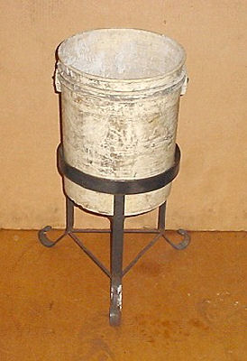
I think a lot of us use a 5 gallon bucket for a quench tub at demos because it is an easy to transport container and is easy to carry from the water supply, frequently we transport our tools in it to and from the demo also. This Bucket Riser elevates the bucket of water so that a lot of stooping to quench things is not necessary. It can also be used as a stool if necessary. -
IForgeIron Blueprints
Copyright 2002 - 2011 IFORGEIRON, All rights reserved
BP0452 Steer Head
by Bill Epps
Start with 14 inches of 1/4 inch X 3/4 inch flat bar.
Split one end about 1 in back.

Use a radius punch at the end of the split this will keep a cold shunt from starting at the end of a split.
Shows the radius.

Spread the end to form a T trying to make the center as flat as possible

Taper and draw out the horns.

Turn over the edge of the anvil make bend as short as possible.

Bend back over it self.
Forge together and shape the face.

Punch nostrils cut mouth and punch eyes.

Shape horns.

Turn heel calk on the other end.

Turn shoe and punch nail holes then you have a horseshoe for a steer roping horse fun thing to make just one of several novelty horse shoes try one just for the fun of it.
-
IForgeIron Blueprints
Copyright 2002 - 2011 IFORGEIRON, All rights reserved
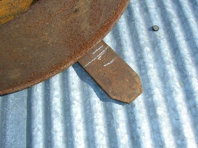
BP0453 Drum Dolly
by Glenn ConnerThere is a 55 gallon drum in the shop where rust, small drops, and any unusable metal is thrown so it can be retrieved later if needed. Keeps the shop clutter down and you know where the small part resource is located. A drum that size fills rather quickly and when full is a beast to move.

I located a couple of pieces of flatbar (leaf springs) and welded them together in the form of an "X". That is two less pieces of clutter already.
Measure from the center of the intersection of the "X" and place 3 marks on the steel at what you think is the outside diameter of the drum.

As you fit the drum, it is easy to align with one short mark, one about right mark and one long mark. You only have to balance the drum on the marks. Now make a full mark across the flatbar.

When you cut, leave this mark showing plus a little, say 1/8 inch or so. The drops are then recut to a length of 2 to 2-1/2" in length.

The drops are now welded to the end of the flat bar.

You can bolt on the wheels or weld them in place. Welding was just quicker in this case.

The drops keep the drum from sliding off the dolly. Notice that they are turned out just a bit so when the drum is placed on the dolly it tends to self align.

No more sweeping everywhere except under the drum, just roll it aside.
-
IForgeIron Blueprints
Copyright 2002 - 2011 IFORGEIRON, All rights reserved
BP0454 Triangulation Layout
for an Odd Shaped Hole
by irnsrgn
Ever had the problem of cutting an odd sized patch to fit something such as the hole ABCDE below.

All a square is good for in this instance is use as a straight edge.
1. lay out line A on the piece you are going to use as a patch and mark its length.

2. take your compass and set it for line B, then using the compass make an arc using its conjunction with line A as the center point.
3. reset the compass to the diagonal x and transfer that distance as an arc and the intersection of lines B and D is established.
4. reset the compass for line C and make the arc as you did in step 2.
5. reset the compass to the diagonal y and make the arc as you did in step 3 the intersection of lines C and E is now established.
6. Draw in lines B and C.
7. reset the compass to line D and E respectfully, were they cross is the last point. connect where the arcs cross and cut it out and it will fit every time.
If it has only 4 sides only one diagonal is needed. Any number of sides can be laid out accurately by the use of diagonals from a known point.
Its so easy and no scrap piece cut wrong. This form of layout is called TRIANGULATION and is as accurate as you are in setting your compass.
I don't want to load this forum down with a lot of information that you will not use, but I can show you how to layout most any thing you want upon request.
Jr. -
IForgeIron Blueprints
Copyright 2002 - 2011 IFORGEIRON, All rights reserved
BP0456 55 More Storage Solutions
by Glenn Conner, Mike Ashley
Ok you got some stuff and need a place to put it. And you want to make it a more permanent type storage facility.
There is a very real danger of explosion at this point.. If you picked up a drum that was reused and filled with a highly volital substance, you will not hear the BOOM. Even an original drum only containing only oil can be dangerous. If you have any concerns, or have never cut into a closed container before, pay to have these cuts made by someone else.

The good old 55 drum comes to the rescue.

This time you drill or cut holes in the rings so you can bolt one drum to another. See arrows.

Do the same thing on the other side of the drum.

Notice the arrows and the washers inside of BOTH drums to keep the bolts from pulling out. This is now 6 connecting bolts per drum, securing to to any other drum it contacts.
Oh yes, drill or cut some additional holes in the lowest point of the drum to let any water drain out. Your building a storage area not a mosquito farm.

Drive a pipe into the ground and rest the drums on landscaping timbers. When you get to the other side, drive another pipe into the ground and tie the tops of the two pipes together with a cable or something to keep them from spreading apart.

When you cut the drums, only cut 1/2 of the head out, leaving the other half to hold the contents in the drum. You will need to protect the edge of the drum still in place. The rind of the drum can be hammered flat. Just use a sledge on the outside of the drum to back up the hammer blow from the inside of the drum. The sharp edge should just lay down flat with a few hammer blows.
The half of the head you leave intact can be protected by folding the metal back over to the inside of the drum and onto itself, cutting a piece of old garden hose long ways and slipping it over the cut edge, or cut a 2" wide section from the part of the head you removed, fold it in half, and cover the sharp edge protect yourself. How ever it is done, the sharp edge NEEDS to be covered..

In just a little bit you have a storage rack. With 7 drums across the bottom, and 5 rows tall, that makes 33 places to store things. Usually 5 tall is about all you want, as any taller and you will definately need a ladder to get to the top row.

There is really no reason to stop there, just use the support pipe on one side as shared support for the next group of drums. And the triangular space where 3 drums join is 3 feet deep. Surely there is something that can be tucked out of the way so the space is not wasted.
For those that don't have that much stuff, or want to store their materials inside, why not modify this just to use 5 gallon buckets, or even one gallon containers.
-
IForgeIron Blueprints
Copyright 2002 - 2011 IFORGEIRON, All rights reserved
BP0458 Dog Head Dragon
by Bill Epps

Dog head dragon I start with a 3/4 sq bar for tis one any size will work the steps are the same i set the end down on the eadge of the anvil this makes what will become the snout

I punch the nostril. eyes and cut the mouth letting the noctrials and eyes flair out
NOSTRILS

From the back of the head I cut what will become the horns after they are split (this needs to be done with a sharp keen edge hot cut )
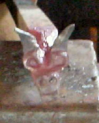
After splitting the horns I use a radius punch to separate the horns and define the eye then open the mouth a little and cut in some teeth and you have a dog head Dragon head. -
IForgeIron Blueprints
Copyright 2002 - 2011 IFORGEIRON, All rights reserved
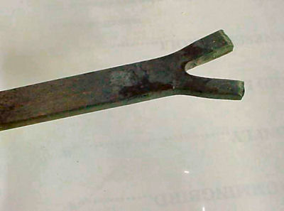
BP0459 Eagle
by Bill Epps, Lonnie RobinsonThis was shown to me by Lonnie Robinson a couple weeks ago at the renn faire hope you all enjoy it.

Standard horse shoe cut in half.

Straiten out the half shoe.

Round off cut end.

Hot cut the cut end back to the first nail hole keeping the cut as close to center as possible.

Now fold back over and flatten back on top of itself.

Now I use a rounding hammer to taper the folded part down to form the head.

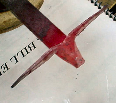
Using the sharp edge of the anvil I set down what will become the beak this will also give the shape of the face.

Now turn the very point of the beak down. I refine this with a file just a little.

Just showing the point of the beak.
Now make two cuts on the tail end --the two out side cuts will become the legs the center will become the tail.

The finished cuts.

Bend the legs down away from what will become the tail.

Cross peen the tail and make it look like feathers.

Now shape the wings also with the cross peen.
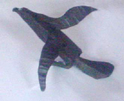
Then it ends up looking something like this little Eagle. -
IForgeIron Blueprints
Copyright 2002 - 2011 IFORGEIRON, All rights reserved
BP0460 Anatomy of a Forge Flue
by irnsrgnHopefully this blueprint will clear up some of the mystery of why a forge flue works or doesn't.
What we are attempting to do by having a flue on our forges is to come up with an efficient means of eliminating the smoke, volatile gases and heat produced by the coal fired forge fire we use to heat our medium IRON , to a suitable plastic state so that we can reform it into the shape of our choice, and maintain a safe environment for our selves.
We are dealing with a heat source that generates a large volume of hazardous stuff we want to get rid of. As it is heated it expands and gets larger, which is a disadvantage, so is hard to control. Being that it is heated it becomes somewhat lighter than the surrounding air and naturally rises which is to our advantage.
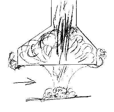
This drawing is of a hood which is an inefficient and less than desirable method of doing the job we want done. The undesirables rise above the fire and have a tendency to collect in the hood where they stagnate or collect and keep getting hotter and expanding. The really hot stuff stays more or less in a column immediately above the fire and goes racing up thru the pipe flue. This makes a sort of venturi effect and draws some of the smoke up into the pipe with it, but the volume in the large hood is too great to suck it all up and out and it accumulates till the hood will hold no more and then it spills over the sides. The arrow shown represents a breeze, and any breeze will push the smoke, fumes and heat away from the direct path into the hood creating a smoky atmosphere to work in.

This drawing shows the basics of what is known as a SIDE DRAFT flue. The Area of the opening "B" cannot be greater than the area of the flue "A".

This side view drawing shows the basics of how a SIDE DRAFT flue works. The block at the base cuts the opening down to about 3/4 the area of the flue and keeps the coal from entering the opening. The smoke shelf "A" gives the smoke something to climb up and also chokes off the area behind the opening so that the smoke has to go up and keep it from making a blockage in the large area behind the opening. The area "B" throttles the area down to about 2/3 the area of the flue and creates a vacuum effect by expansion so that the smoke, heat and if its working right will even draw the flames into the opening.

This drawing shows the top of the flue with a screen spark arrestor and rain cap installed. The rain cap should be rather flat with just enough slope that rain will run off. To determine the height above the end of the flue, find the area of the pipe, radius squared times pi (3. 1416) and multiply by 3. Divide this number by the circumference, diameter times pi. and the result will be the inches above the flue needed.
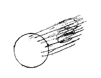
This drawing shows why the area is 3 times the actual area of the flue pipe. In a brisk breeze all the volatiles will need to exit out approximately 1/3 of the pipes circumference.

This drawing shows why you don't want a high peaked rain cap. The severe angle will make the smoke roll in the top of the cap and in effect make a sort of plug that will block the natural flow from the flue pipe.

This drawing shows the recommended height of the stack for a low angled roof, it should be 3 to 4 feet above the peak or highest point of the roof. For a steeper angled roof it should be higher as the wind is channeled by the roof angle and the air will kind of expand on the lee side of the peak and make down pressure as it rolls over the peak.

The arrow is pointing to what is called an escushion, which is a tapered ring fastened to the flue pipe at its very top and it funnels the wind up into the exhaust area to enhance the natural suction of the flue pipe.
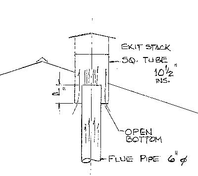
Having an open bottom esit stack as shown here seems to increase the draft in the flue pipe. The natural draft of the building through the exit stack provides a lot pressure area just above the flue pipe to aid in extracting the coal forge gasses.
Dimension "d" the amount the flue pipe sticks up into the exit stack is adjusted for maximum draft.
Several different shapes of the flue exit were tried. A simple square cut seems to work as well or getter than other shapes.
The flue pipe is centered in the exit stack with a light spider made from round bar. The weight of the flue pipe is carried by the side draft forge hood below. Jim Carothers
-
BP0466 Third Hand Anvil Tool for holding flat stock on edge
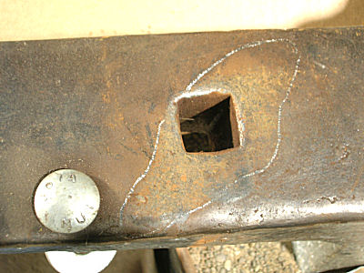
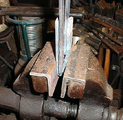
by irnsrgnOne of the more difficult tasks for a smith to perform without an assistant holding the work piece is working a piece of flat with auxiliary anvil tools in one hand and a hammer in the other hand to perform a specific task while a piece of flat iron is standing on edge on top of the anvil. He just doesn't have enough hands.
A few years ago I was confronted with this problem when mass producing some parts for a customer, and this simple little tool became a reality to solve my problem. Its just one of those spur of the moment cures that happen occasionally that we take for granted after the problem is solved.
I have made several different styles of these little tools over the years and I made this one especially for this Blueprint to show how the basics of how I made them.
This is the very first one that I made and even though I now make a different style it still got used often. The basic idea was to have something that would hold a piece of flat on edge while it was being worked, but not to be difficult to use, but still hold the work piece firmly and securely. It works by being slipped into the hardy hole of the anvil and the spring tension created by it being slightly wider than the hardy hole provides the security needed.
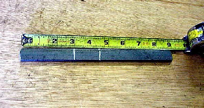
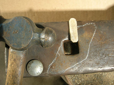
The second style will be shown here. I started with a piece of 1/4 by 3/4 flat 9 inches long and marked the center and another mark 1.5 inches from the first. My Hardy Hole is 15/16 so I used 3/4 as it does need to have a little clearance for a slip fit for ease of application.

I used a bottom cold cut hardy to make two edge marks that can be seen when hot at the chalk marks. There will be a 3/16 inch offset at the second mark. 15/16 inch hardy hole minus 1/2 inch for the thickness of the material, leaves 7/16 inch between the legs at the bottom. To make it grip snugly on 1/4 inch material a 3/16 offset is needed near the top.

To make the offset easily, I will use my 3/16 inch offset tools (BP0381) and my spring auxiliary vise jaws.

The offset tools and vise jaws set up ready to make the offset.

The piece is heated, held in the proper position and the vise jaws closed tightly.

The piece is reheated and the center mark is held just past the end of the vise jaw spring tool and bent using a pair of side ring tongs.
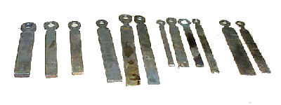
Now a spacer tool 1/4 inch thick is laid out to help with maintaining the 1/4 inch gap needed after finishing the 180 degree back bend. I always had short pieces of various width flat stock left over from cutting up 20 foot pieces of stock. So I collected various widths and thicknesses and fullered, punched and drifted hanging holes in one end so they could hang in a close convenient location to my anvil. left to right - 1/2 - 3/8 - 5/16, the next 4 are various widths of 1/4, the next 3 are various widths of 3/16, the end 2 are 1/8 thick. I also use them as width gauges instead of a ruler when I need to extend a hot piece a certain distance past the end of a hot cut or set of guillotine dies.

This shows the 1/4 inch thickness spacer and a 3/16 inch spacer held in place by my left hand offset jaw tongs after the straight side has been hammered down and wrapped around on the end.
This is an alternative method to tightening the wrap and insuring the 3/16 inch offset is maintained.
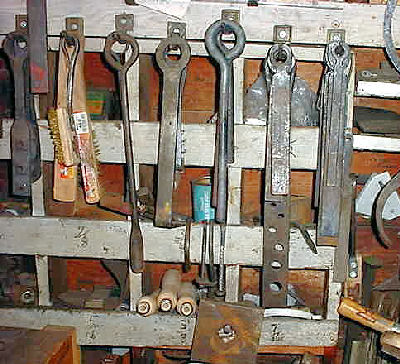
Various flat and round tools hanging convenient to the anvil for easy access.

The tool is inserted just barely into the hardy hole, then the work piece is slid between and the tool either just pushed down with the hand or tapped into place with a hammer.

A wider piece being held in place.

Various edge holders, the one on the right was made for this Blueprint. The second from the left is the most used as it has a bit longer legs and will work with most sizes up to 7/16 inch thick material. The far left one is for 1/2 inch material as it is made from 3/16 inch thick stock.
This Blueprint shows several of my other not shown before special tools and a couple of my specialty tongs in use. -
IForgeIron Blueprints
Copyright 2002 - 2011 IFORGEIRON, All rights reserved
BP0464 Mini Traveler
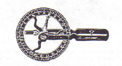
by irnsrgn There are many varied ways to obtain the length of a scroll or other line on a drawing. String, reel solder, dividers, etc. If we look at history one particular tool the smith and wheelwright used for accurately determining the necessary and accurate length of iron for the tire on a wooden wheel was the traveler.
It still is extremely accurate for measuring although a little too big for the job at hand. Woodworkers have been making mini travelers for years. So lets make a mini traveler with a 2 inch wheel so you can see how well it works.
Plan One
--------------------------------------------------
traveler 000 -

Some old traveler wheels are graduated around their circumfrence while others have a single starting mark and a pointer to show the ending. To use, you line the starting mark with a mark or reference point of the end of something and roll or travle it along the line counting how many revolutions it took and then making a mark or setting the pointer at the ending mark.
A measuring wheel.
---------------------------------------------

traveler 001 - Using a scrap of light sheet metal and a 2 inch hole saw, saw a hole in the scrap.
-----------------------------------------------------------

traveler 002 - The part we are going to use is the slug or part that was sawn out.
------------------------------------------------------------------------
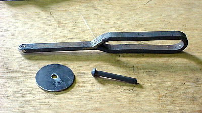
traveler 003 - Remove all the sharp edges on the slug. Then using a 13 inch long piece of 1/4 by 1/2 flat or other suitable material at hand, make a handle similar to the one shown, and find a 1/4 in rivet or bolt to make the axle from.
--------------------------------------------
traveler 004 - I drilled a 5/32 hole in the end of the handle and using my lathe made a shouldered rivet for the axle wheel. You could just drill a 1/4 hole and slip the rivet in with the proper clearance and weld in place.
-----------------------------------------

traveler 005 - The finished Mini Traveler, notice the chisel mark with yellow paint from a paint marker to hilite it, and the chalk mark to mark the end .
-----------------------------------------
Plan two

traveler 006 - Go to wood shop, use hole saw to saw scrap paneling, clean up edges, pick up scrab piece for handle and drill hole and find screw to hold it.

traveler 007 - 10 minutes later a simple easy traveler, but not for hot work.
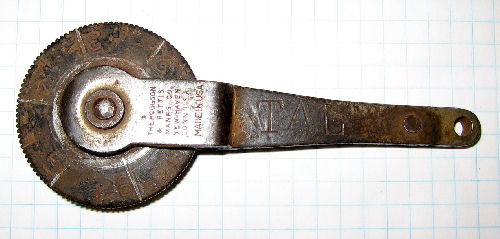
6 inch travler by Tal Harris. -
IForgeIron Blueprints
Copyright 2002 - 2011 IFORGEIRON, All rights reserved
BP0463 Wheel Forge 2
by Glenn ConnerThe first wheel forge was made to see if you could make a forge from a car rim that would run on wood as a fuel. Yes you can. It works better on coal.
This forge was the second generation wheel forge with coal as a fuel. The fire pot needed reduced and redefined so you could get a better shaped fire that would burn more efficiently.
Start by getting some clay. Usually a creek, stream, or river bank is a good location, but any clay will do.
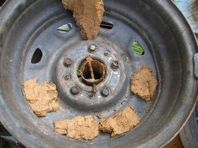
Locate a car wheel or rim and start by placing a tuyere in the wheel. (See Blueprint BP0133) Then pack the holes with clay.

Tamp the clay tight and fill up to level with the twere.

Put a flower pot in the center of the wheel as a form. Yes they usually use a clay flower pot but the plastic one was handy. No one said you could not overcome a lack of materials and improvise when needed.
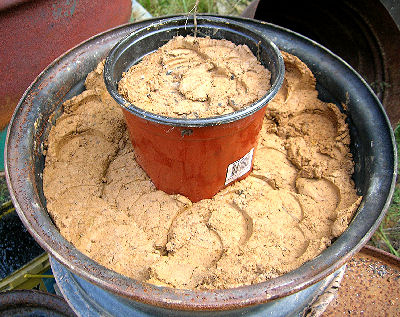
So the thin plastic does not deform, fill it with clay also. Continue to fill the wheel with clay tamping it tight as you go.

Once you get the wheel full, try to get the top flat, or reasonable flat.

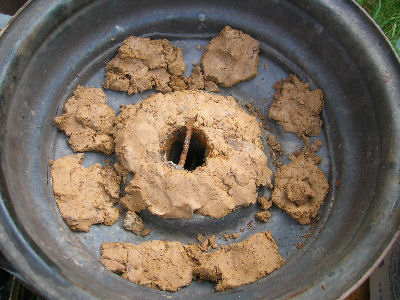
Remove the flower pot.

The hole is about 5 inched deep.
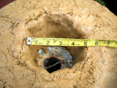
And about 5 inches in diameter.

Ahh now the fun part. We just sprinkle the clay with a little water and play. The clay will liquefy and we can smooth it out for a professional finish.

Don't forget the inside. Just add a little clay where needed and blend everything into a nice smooth transition.

Finish the top.
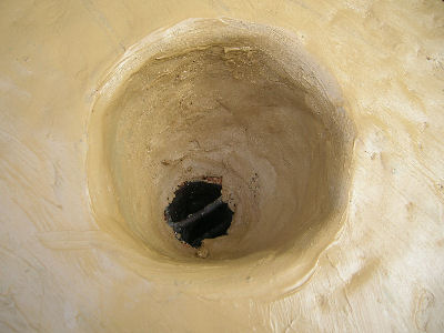
Then finish the inside by adding a sprinkle of water and a bit of clay into any depressions so things end up smooth.
Building a forge is not an exact science. You have different resource materials, and a fuel that burns differently than what is available here. Build a forge, build a fire and play. Then alter the forge so it works for you, providing the type and shape heat you need for the type blacksmithing you do.If this type forge were going to be used for more general heating, I would alter the fire pot by removing the clay at the top so the rim would be maybe 7 or 8 inches in diameter and transition to the twere at the bottom of the fire pot. I would suggest the wheel forge could be used in many different configurations but I will have to use it before I can make suggestions as to it's capabilities.

Well, the next morning I looked at the hole and decided that it needed changed, altered if you will. It is now 8 inches diameter at the top.

In talking about this in the IForgeIron Chat room it was suggested to add a few holes for any steam to escape during the fire and the drying process. That way there is no steam explosions and hot clay flying all over the place. Thanks fellows for the advice.
Update:
The first fire in the forge was with wood, just set on fire and left to burn with no air to dry out the clay. A coal fire was built the next day and the firepot is too small. There is just not enough volumn in the fire ball. The fire heats aobut 3" of steel up to sparkling heat, and be good for points, nails, etc. It required just too much fire maintance for my liking.
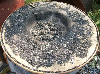

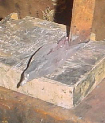
The crack was expected. The crusty "glass" substance on the edge of the fire pot walls is part clinker, and who knows what else was in the wood and other things that made it into the fire.
Next attempt will be to enlarge the opening from 8" to maybe 13" diameter. All this will most likely end up close to the "standard" size fire pot used on many forges today. By reinventing the wheel so to speak, you learn that things work for a reason.
-
IForgeIron Blueprints
Copyright 2002 - 2011 IFORGEIRON, All rights reserved
BP0462 Wheel Forge
by Glenn Conner
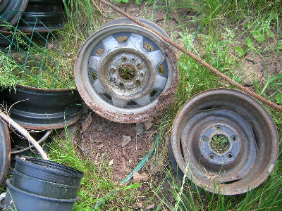
First off, find a wheel. The one on the right has a raised center, which will make the fire pot more shallow.

The one on the left is much flatter and will make a deeper fire pot.

From the scrap pile (er resource center) recover the original tuyere to the first 55 Forge. See Blueprint BP0133 for construction details. After 3 years of hard use in the 55 Forge, it is still serviceable.

Place the tuyere in the wheel forge.
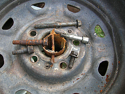
From the resource center collect some filler material for lug bolt holes.

Lug bolt holes are now filled, but what about the larger holes?
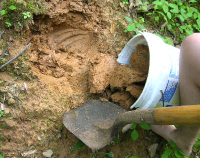
A trip to the creek, stream, river, etc will supply you all the clay you will need.

Just fill the holes.
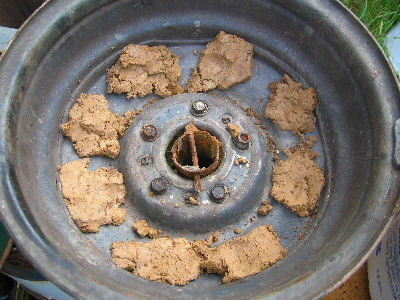
No need to get fancy as the fire will bake the clay into a hard material.
I built a little cone around the twere so any clinker would not get hung on the filler bolts. This is not necessary, just my thought at the time.
So far we have 45 minutes time in the project to this point. This is nothing more than a holder for a fire. No use trying to over engineer things. If something needs changed, we can make the adjustments as needed.

Time for a fire.
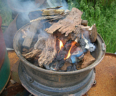
Add scrap wood from the yard.

A little air and a little more wood.
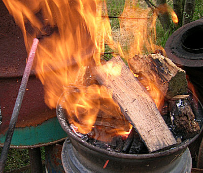
25 minutes later we have iron up to red heat.

A little more wood and a little more air and still at red heat.

All this is just a starting point so we can make improvements. This set up seems to get only to red heat, so we need to think about what to do to improve the forge.

The fire ball seems about right in diameter, but the 2 + inch tuyere is allowing a lot of air into the fire pot. We are not able to get far enough above the tuyere so the air is actually cooling the metal. We need a deeper fire to solve this problem. A side blast air pipe may help solve the problem also.
We also will need a table of some sort around the wheel. Some of the wood stacked on the fire falls off and onto the ground. A deeper fire pot will help, but a table is nice too.
45 minutes to build the forge, 25 minutes to get the metal up to red, Total time = hour and 10 minutes (this includes gathering fire wood). IF you were to build the tuyere you could still have the forge built and metal up to red in under 90 minutes.
If you were to use coal as a fuel, I think it would be serviceable forge. I would still consider a table of some sort to both keep the fuel from falling on the ground and to hold the tongs etc.

Now where did I put the marsh mellows ??
The forge charcoal was still HOT after 7 hours of being idle. This means that fire safety is most important. The best way is to shovel the coals into a bucket of water. You can sleep well at night knowing that there is 2 inches of water covering the coals. The charcoal can be recovered and dried out for later use.

The following day I took a look at the results of the fire on the clay.

The clay shows the results of the heat at the opening and how the rest of the clay hardened.
Final review:
The wheel forge is not deep enough for wood as a fuel. There is not ehough volumn of material being burned and reduced to charcoal. To add a second wheel may work, but cutting out the center and then cutting an entrance for the stock to go through is a lot of work. I looked at adding 1/2 of a hot water tank to the top of the wheel, but again there is the cutting of a entrance. I also looked at a larger 16 inch truck wheel and a container for the wood which could have worked but only with cutting an entrance for the stock. The 16 inch wheel assembly would have been very awkward to use because of the size of the container used to hold the wood.
With the cutting required for improving this style forge, you could have built a Supercharged 55 Forge (Blueprint BP0333) and been forging already. BP0333 will work with wood as a fuel, as I have done that already.
Save the wheel forge for coal.
-
IForgeIron Blueprints
Copyright 2002 - 2011 IFORGEIRON, All rights reserved
BP0433 Forge Station
by James Joyce

This might seem a strange idea to you, but for a single photo stand alone blueprint, I submit the attached pic of my gas forge work station.
What makes it different? It is a clean, safe work environment where all tools are in their proper place, the floor area has no trip, stumble and fall hazards, the lighting is good and all forge stations are within 2 steps of the forge.
The lower window are clear plexiglas shaded from direct sun by trees. Upper wall is opaque fiberglass for indirect light. Nearly the entire back wall (lower half, which is over 7 feet high) opens up to allow cross ventilation when useful. This gas forge station contains, in a 12' x 16' area: a 100 lb power hammer, forge and slack tub, hydraulic press, treadle hammer, 3 anvils (150# english, 243# euro, 230# english), swage block/stand, work bench with a post vice, hammer rack (2), and 8 foot hardy rack and 6' x 12' tool holder wall, and 2' sq portable table.
And the photo is after work today with no clean up other than running the broom. Sometimes I think we give beginners the wrong idea when we talk about the "humble pile beneath the forge." We may be inadvertently encouraging new guys to be sloppy and create unsafe industrial atmospheres.
-
IForgeIron Blueprints
Copyright 2002 - 2011 IFORGEIRON, All rights reserved
BP0447 How to make a Froe
by Glenn Conner
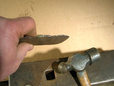
Find a leaf spring that has the formed ends where it is attached to the vehicle. Heat a leaf spring to get the metal up to forging temperature, and to burn out the rubber bushing.

There was no reverse curve put in the metal. As the blade was thinned or sharpened the metal curved. Think of making a knife. You have to make a reverse curve in the metal before you start, and as you thin and sharpen one edge it will straightened up.
Keep the blade straight in all directions.
As things progress keep things straight. The sharpened or thinned edge is toward the hammer.
The straightened blade.

Either a micro-fracture in the steel, or I got it too hot and it burned the steel, but it is clear something happened, and this fracture in the metal ended the project.

And it would have been a nice froe.
No one said everything would work the first time. A little problem only means you have to rethink the process and figure out what went wrong.
We still have one more chance with the "other" end of the spring, so let's get started.
Heat the spring and straightened out the metal.

The factory formed end is in line with the blade, and the metal is straight.

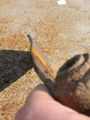
Place the metal in the vise and with a 4-1/4 inch grinder and sharpen the edge.

Flip it end for end and sharpen the other side.

The blade is still straight.

Weld the gap between the loop and the blade.

Add a wooden handle made to fit the loop in the metal and you will be ready to start riving wood.
Shakes (wooden shingles) are cut from blocks of wood, the shake bolts. The technique of riving is really rather simple. To start the froe in the bolt, hit the back of the blade with the mallet. The thickness of your shake is determined at this point. If the shingles are splitting a too thin (less than 1/4 inch) then start a bit further from the edge the next time.
When the back of the froe is level with the end of the bolt, pull or push (whichever works best) the handle twisting the blade. This opens the split and the froe is pushed down three to six inches. Twist again and the shake should pop off the bolt. After an hour or so of practice you should get the hang of it. A square is 100 square feet of roof. You should be able to split about a square of shakes in about an hour.
James Joyce
Out west , here, we cut the log sections 3' long. split out about 4" x 6" bolts. Leaving the shakes 6" wide, we rivwe one end every 3/4" beginning at 3/4" from the face. Flip ends and begin at 3/8", riving every 3/4" from there. This leaves the shakes attached like an accordion. The roofer pulls them apart on the roof. -
IForgeIron Blueprints
Copyright 2002 - 2011 IFORGEIRON, All rights reserved
BP0428 Air Gate
by Ten HammersWhen I finally joined the 20th century and got the power blower, I built this airgate.

Pretty simple. Scrapped 3 "cyl tube. Chopsaw almost all the way through. Make a disc to fill the slot ( 12 ga ) and leave a place for a hinge and to attach the handle.
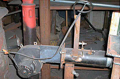
Rest is pretty much self explanatory. Scrapped downdraft furnace blower ( now 5 years old in my shop ). Blower runs off a toggle switch on the forge and blower runs full blast. Airgate controls it all.
-
IForgeIron Blueprints
Copyright 2002 - 2011 IFORGEIRON, All rights reserved
BP0443 Making Charcoal
by Irnsrgn
Take a 55 gallon drum with one end cut out, and a 1/2 inch hole poked in the other end centered, fill with smaller short chunks of dry wood, place chicken wire over the top and secure in place around the top with baling wire. Carefully upend the barrel and place a fire brick under one edge as shown, using shavings and kindling start a fire as shown.

When the wood in the barrel catches good, remove the brick and mound loose dirt around the barrel except a small air opening shown by the arrow.
Smoke will exit from the hole in the top, light this smoke on fire, it will burn on its own after ignited, when the flame goes out on its own, drop an old 1/2 inch bolt in the hole and close the air opening at the bottom.
When the barrel is completely cold, turn it over remove the chicken wire, dump the contents out and you have charcoal, you will need to break the bigger pieces up into usable pieces about the size of walnut or smaller.
A Charcoal fired forge burns lots of charcoal and has lots of fleas or sparks that rise in the hot air and fumes, so be careful of starting grass fires.
You can use wet charcoal at the sides of the fire to help maintain the small hot fire needed for smithing, not the large bonfire. -
IForgeIron Blueprints
Copyright 2002 - 2011 IFORGEIRON, All rights reserved
BP0461 Anvil Hold Downs
by Coalforge Irnsrgn, Jerry, Tiian, Jim (PPW) Wilson, Dimag, JWBIronworks
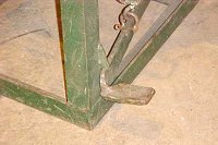
A holdfast or stock holder for the anvil. This was from Tiian in South Africa. Note that there seems to be no heel on this anvil.
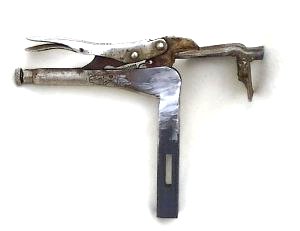
A modified pair of vise grips for an anvil hold down. The slot in the bar is for a wedge to tighten the clamp against the anvil. PPW
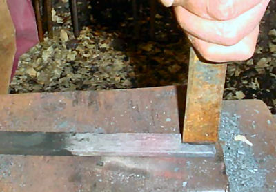
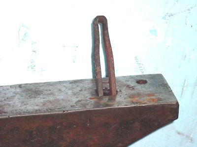
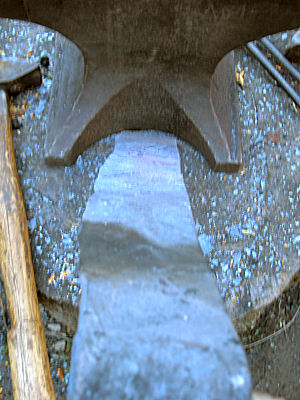
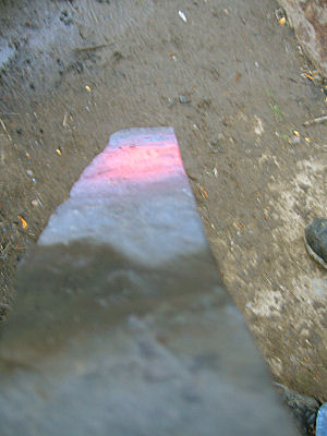
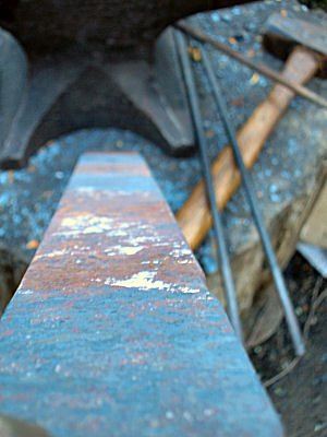
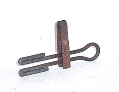
Shows flat iron bent so as to fit snugly in the hardy hole of the anvil. I have several for different thickness's of material. they are about 4 in long. Irnsrgn

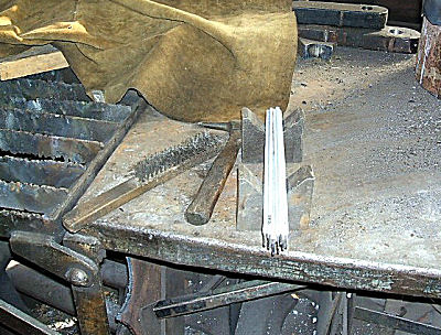
Shows a piece of material on edge in the holdown ready for an operation to be performed on it, this is one of the hardest things to do for a single smith. Irnsrgn


The other 3 pictures show a 1/4 in spring fuller, a 3/8 spring fuller and a spring side set, for use with the holdown. This type of spring tool is easy to make as there is no need to make a shank for inserting in the hardy hole, and they may be used as hand held tools too. irnsrgn
2 of my hold downs.
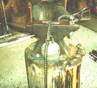
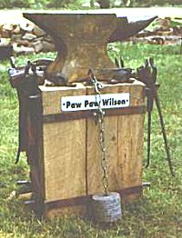
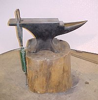
The 6" cast iron ball is attached to a length of industrial sprocket chain that is hooked to the back side of the anvil stump and hung over the anvil--the chain doesn't look very traditional but it works!
The 6" vise grip hold down is from my drill press table. I made a coupling to extend the mounting bolt below the hardy hole far enough to go thru a piece of pipe, angled cut on the top to fit the bottom of the anvil and cut straight on the bottom with a washer welded on so the nut don't go in the pipe. The hold down can be turned so long pieces can be held length-wise on the anvil. I've made several changeable feet for the jaw to hold different shapes. I gotta patina the thing now so it looks like it's used! Jerry
Down next to the ground, see the lead weight cast around the end of the chain? Flip it over the anvil, and the chain holds the work down. Half of a two pound coffee can filled with molten lead. After it set up, peel off the can.ppw


tension on the spring but there is very little tension with the pedal unhooked. The wood stand has a railroad spike driven into it to hold the pedal down but it is bekind the pedal and not visable.
This hold down uses a large spring for the tension and it is tightened by stepping on the pedal. To stay clamped, the pedal goes under a hook. This is strong enough, you can not lift the holder when there is
that metal stand and anvil is the one I use at demos. Moves easy on a hand truck and I can set the anvil against the truck tailgate and flip the stand over the top so I don't have to lift it. CoalForge


I attached a couple of pictures of my anvil hold down. I can't remember where the idea came from but it's not mine. If you just use the roller chain it only goes in one axis. That makes it hard to keep out of the way when your not using it. I added 3 links of regular chain to each end so that it will swivel 360 degrees, alot easier to use this way. You can't see it to well in the picture but the chain is lag bolted on the side of the anvil stand facing you as you normally forge.
I have one that is a square made out of 3/8sq.that will fit over the heel of my anvil.It has a spring attached to the bottom bar and the other end of the spring is attached to my anvil stand.It has a small handle welded to the top bar.I have it set so the hold down sits a couple of inches ahead of the hardy hole,that way you can work both sides of the hold down and still use your hardy hole. Pull it off of the heel and it flops down out of the way.Dimag
Also reference:
Blueprint BP0409 Anvil Hold Down
Blueprint BP0457 Anvil Hold Down
BP0441 Welding Rod Holder
in BP 400 Series
Posted
IForgeIron Blueprints
Copyright 2002 - 2011 IFORGEIRON, All rights reserved
BP0441 Welding Rod Holder
by Irnsrgn aka Jr. Strasil
A welding rod holder can be as simple as a piece of square tube with a bottom welded onto it.
or, two pieces of plate cut in a "V".
A longer section of square tube will hold the rods in place by its own weight and they won't roll around loose.
For a permanent storage area out of the way to protect the rods when not in use, A cabinet with a door properly labelled is necessary.
Viola!! All the different rods by size and type neatly stored and readily accessible as needed.