

Steve Sells
-
Posts
9,162 -
Joined
-
Last visited
Content Type
Profiles
Forums
Articles
Gallery
Downloads
Events
Posts posted by Steve Sells
-
-
IForgeIron Blueprints
Copyright 2002 - 2007 IFORGEIRON, All rights reserved
BP0279 New Handle in a Sledge
by Stephan Fowler

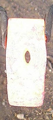
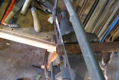
A Salvaged 8lb sledge head from my local junk yard

All the pieces ready to begin

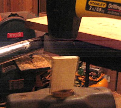
We need to start by removing the old handle. Start by sawing off any remaining protrusions of wood.

Once the outside wood is removed we remove the wood from the inside. I used a 1/2 in drill bit to drill 2 holes in the eye, one on either side of the locking wedge (metal wedge cross grain to the shim). It is possible to drive the old wood out with out drilling holes, but can sometimes be stubborn.

Use a piece of scrap or a drift if you have one large enough to drive the wood out of the eye.

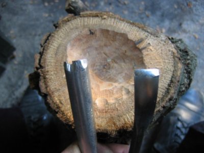
Here we see the head cleaned and ready to install, check the inside of the eye for rust or protrusions and remove as necessary (this helps to get a good fit around the entire circumference of the eye). Also, this is probably a good time to grind out any major flaws in the face, or (depending on your needs) reforging the hammer to "customize".

For a large hammer like this, I set the head on the ground and tap the handle into it (*NOTE* the handle should NEED to be driven through the eye, it should be tight), make sure not to mushroom the bottom of the handle by hitting to hard, or use a block of scrap wood as a sacrificial beater.
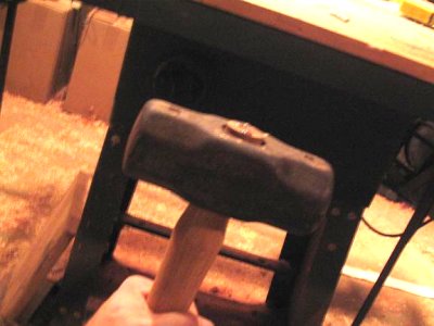
Then flip the hammer over so that the handle is on the ground and tap the head down onto the handle until it bottoms out.
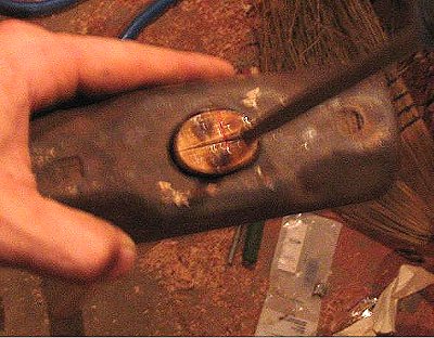
Now you will probably need to take a flat head screwdriver or a chisel and gently open the shim slot to allow installation of the WOOD shim (don't drive very deep, 1/4 inch is probably enough)

Looks like this
(*NOTE* you really should throw away the soft shim that came with the kit and cut your own out of a well seasoned piece of hardwood) Drive the WOOD shim into the slot, make sure you hit square, and keep driving until its all the way in.

You should have some excess material sticking out the top of the eye at this point. It's not necessary to trim this, and some would argue that leaving the wood makes a longer lasting fit, however, I think it looks much more neat and tidy if you trim flush with the top of the eye.

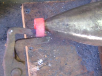
Now install the locking METAL shim. DO NOT make a groove for this shim using a chisel like we did for the wood shim, you want a super tight fit. Drive the shim ALL the way in, 45deg angle to the wood shim.
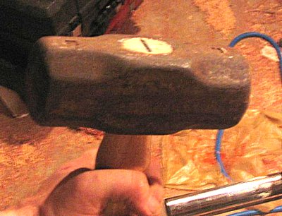
Voila, a rehafted hammer. Soon I will show how to make your own handle. I find that the wood used in store bought handles is marginal at best.
-
IForgeIron Blueprints
Copyright 2002 - 2007 IFORGEIRON, All rights reserved
BP0277 Scott's Coal Forge
by Jerry Carroll
to get started in blacksmithing and needed a forge. This forge was put together from parts that were laying around the shop.
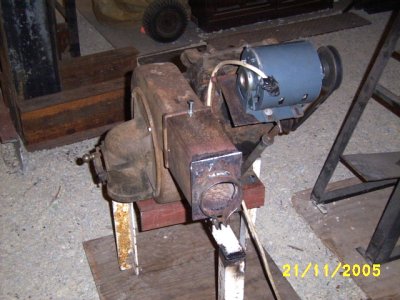
The blower and auger drive is from a coal furnace stoker -- Norge
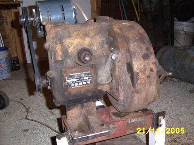
The blower needed a motor, so one was located and attached.

I used an old car brake adjusting star wheel set-up in the end of a length of pipe--works great!

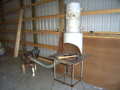
I'm cutting the ends out of old water pump holding tanks and welding the tubes together for 12" heavy wall stack.

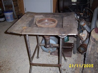
The forge table has a really big fire pot without the full size car brake drum. The drum makes a real nice sweet spot that can be big enough for good size stock--we had a fire in it already. The area around the drum will be filled either with ash or some of the clay from the river bank here.

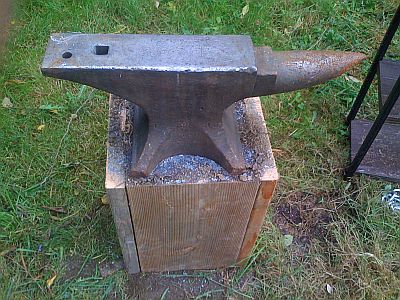
The anvil is a 130 lb Trenton I found for $130.00--excellent shape!! I just found a 400 lb anvil I haven't seen yet for a $1 a pound and a bunch of tools in an old barn just to get them out of the way!! I don't get out much but when I do and I'm scrounging Carol has another heart attack! Talk to you later,
We plan to finish the installation soon, he's got a lot of potential with the new 2 story barn.
-
IForgeIron Blueprints
Copyright 2002 - 2007 IFORGEIRON, All rights reserved
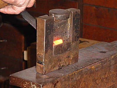
BP0276 Rivet Header Helper
by Jr. Strasil
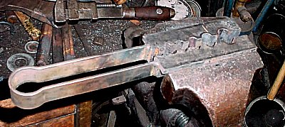
This Handy little tool for the vise, is what I use for rivet heading. It is made of 1 inch cold rolled square with an under cut milled in on each side and a spring handle to keep it lined up and also to force it to spring open and stay in the vise. It was tack welded together and then the holes all standard size were bored at the joint. 3/16, 1/4, 5/16, 3/8, 1/2 and 5/8 inch. It will work good on hot rolled as it is oversize, but doesn't work to well with cold rolled.
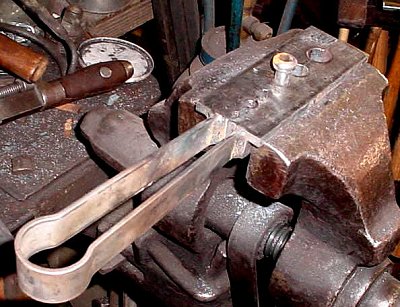
To use I put a light center punch mark 1 1/2 times the diameter from the end and then use the upset helper to upset the end some. I then take another heat and position the center punch mark a little above the top of the header helper as it will move down a little. The standard holes have a tendency to grip the material and you can start the heading process. I have several heading punches for a regular head and also the button or phillister head shown. For a wagon box or truss head I just carefully hammer the head down.
-
IForgeIron Blueprints
Copyright 2002 - 2007 IFORGEIRON, All rights reserved
BP0275 Basic Hydraulic Press Diagram and information related to it's function
by Irnsrgn
Warning: Hydraulics and presses are not to be taken lightly as tons of force can be exerted with little effort on the part of the operator. If there is a leak in the system, hydraulic fluids can, when under pressure, be easily driven through the skin and into the body or even cut flesh. Under certain conditions they can be fl amiable. Read and understand the subject before attempting to build or purchase or operate this type equipment. There are very real dangers associated with this project. Please read and understand the site disclaimer.
PSI = Pressure per Square Inch HP = Horse power ID = Inside Diameter A = Area in cubic inches D = Diameter pi = 3.1416 r = radius Bore = the inside diameter of the cylinder Ram = The shaft that comes out and does the pushing or work Stroke = The distance the Ram comes out when fully extended Working pressure = the pressure developed by the cylinder
GPM = Gallons per minute of flow
Hydraulic hose comes in 2 basic types, single wire braid - usually with a 2000 PSI limit, and double wire braid - usually with a 3500 PSI limit. Hydraulic hoses offer more flexibility when piping a hydraulic system and you have fewer joints to potentially leak than with threaded pipe, and vibration does not bother them as much.
A large GPM pump will require a Large HP motor and the Cylinder will have a very fast stroke and therefore dangerous as it is hard to control. And this equals a higher initial cost.Pumps- there are several different types of hydraulic pumps:
A Vane Pump will give lots of Volume but does not develop a lot of pressure.A Gear Pump will develop the pressure needed, and has a good volume, but requires a larger Motor. It is relatively simple and trouble free though.
A Piston Pump has many small pistons and will develop a great amount of pressure with a smaller motor, but lacks a great amount of volume. This type of pump is usually more initial cost, but is best for a hydraulic press.
Valves - come in numerous configurations, I prefer one with a built in pressure relief valve, as you can regulate the pressure you need for your application. Its also a big safety advantage against rupture of oil lines, and the chance of pushing your press apart if not built heavy enough. The system shown is an OPEN system where the fluid circulates continually until the valve is manipulated causing the oil to flow to one side or the other of the cylinder.
Cylinders - come in many different sizes and shapes with many different sized rams (the rod that does the pushing). A small cylinder is just that, a small cylinder and it will have a small amount of push. For a press the ram should be as big as possible to prevent bending as you will be pushing against an almost immovable object. And select one that has a sufficient amount of travel for your purpose.
Oil Reservoir - This container holds the oil you will use to operate your press and should have a sufficient capacity to keep the oil cool as it recirculates in the system.
Oil- this should be any good quality, antifoaming oil suitable for hydraulic systems.
Filter- this is a special filter for hydraulic systems with a spin on replaceable filter and should be mounted close to your reservoir in the return line.Press Frame - draw a diagram of what you have available to build you frame with and have an engineer spec it with a safety factor of 2 before you start, make sure you tell the engineer what working tonnage you will be using.
Frame Pins - The pins that hold your press together at the top and also the bottom table. These need to be of sufficient size to withstand the pressure you cylinder will develop with the cylinder of your choice, and should be more than 1. These need to be spec'ed by an engineer too. Remember to use heavier pins in the top part than the table.
Valve mounting position, this should be at a comfortable place for easy and frequent use, but still out of the way of normal operation.
Press Feet - these should be of sufficient size to keep you press from falling over on you.
Cylinder size - determining the amount of pressure your cylinder will develop.
find the ID and use this formula for the area, A=pi r². Multiply the Area of your cylinder by the amount of pressure your pump develops.
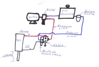
Suction line - this is the line from your reservoir to the inlet on your pump and should be of a larger size than your pressure and return lines so as not to starve your pump and thus cause excessive wear and premature failure of the pump. This line should be several inches up from the bottom of your reservoir to prevent solids and settlings from the system being introduced into your pump.Pressure lines- These are the lines from your pump to your valve and from the valve to your cylinder, and carry whatever pressure your pump develops.
Return line - this is the line from your valve that returns the fluid to your reservoir.In the following diagram, PRESSURE lines are RED, RETURN and SUCTION lines are BLUE, and the cylinder return line is BLACK. The diagram shows no pressure gauge, but one should be put in pressure line to the top of the cylinder so you can calculate what WORKING PRESSURE, you are developing.
click to enlarge
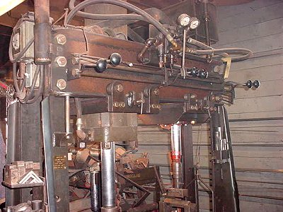
Now my shop press, mainly used for straightening things and pushing large things apart, has 10 inch channel iron with a 5/8 web thickness for the top with a bridge truss of 3/4 by 2 flat to prevent bending it. The table is the same material, without the truss, but if bowed or bent can be turned over.
The side uprights are 3/4 by 4 1/2 on the side where the big cylinder is and 3/4 by 4 on the side of the smaller cylinder.
The 3 Pins on each side that hold the top together are 1 1/4 inch cold rolled shaft, threaded both ends with a nut on each end.
The 3 table pins on each side are 1 inch cold rolled and just drive or slide in. With a safety factor of 2 they are rated at 76 tons.
The Motor is 5 HP, 3 phase, 3400 RPM,
The Pump which you can hold in your hand is a piston pump, it has either 7 or 9 pistons about the size of a cigarette and is a military surplus item from an airplane and is rated at 3GPM - 3,000 PSI - 3,000 RPM.A=pi r² so A = 8.625 divided by 2 x's itself x's 3.1416, thus 18.59765625 x's 3.1416 =58.426396875 times the working pressure of 3,000 PSI = 175,279.190625 lbs of pressure, if we divide this by 2000 lbs which equals a ton we have 87.6 Tons of pressure. Remember the 76 ton spec from the engineer, my relief valve is set at 2600 lbs or 76 ton of working pressure .
The Big Cylinder is also military surplus from a bulldozer, it is 8 and 5/8 ID and has a 2-1/2 inch ram with 32 inches of stroke. Lets calculate the working pressure of this cylinder.
The second cylinder is only 7 inches ID and has 13 inches of stroke with a 1 7/8 diameter ram, so has less power than the big one.
-
IForgeIron Blueprints
Copyright 2002 - 2007 IFORGEIRON, All rights reserved
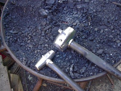
BP0274 Lead Hammers
by Richard B. Jensen
Tonight's Blueprint is "Pouring Hammers". We'll look at pouring a lead hammer
First we need to talk safety. Lead is a very dangerous and toxic substance to the human body. First is as a heavy metal. It can be ingested as dust, or inhaled as a vapor when it's heated up. It has long term affects that can't be cured, once you get it, your stuck with it.
The other way lead can be dangerous is in a molten form. The melting point of lead is 621 degrees. That's not hot enough to start a piece of wood on fire but it would severely burn the human body. When lead is at a molten state, it is just as fluid as water, but it has all of the weight of solid lead. Remember if you have a small piece of lead that you want to add to the melt you need to be very careful. One, if you just toss it in it will splatter. Even a small piece has a lot of kinetic energy in it, a lot more than something else of the same size. The other danger with tossing a chunk of lead in the melt, is its moisture content. If it has a high moisture content you could have a "steam explosion".
Water and molten metals act kind of strange until you understand what's going on. The explosive content of a drop of water (or sweat) is amazing. One drop of water will expand 1500 times its original size almost instantly, read that as a explosion of a mist of molten metal going everywhere in the immediate area. That means the plastic fuel can in the corner,,,,,boom! You need to be aware of your surroundings and the potential dangers.
You should work with lead in a well-ventilated, dry area, preferably outside. No rain! I'd recommend a respirator, full-face shield, welding jacket or cape with sleeves, boots, good jeans and gloves. The same for anybody helping you. Remember anytime you touch lead with your bare hands your coming into contact with a toxic substance. WASH YOUR HANDS!
Now that I've put the fear of God into you, lets get to work!


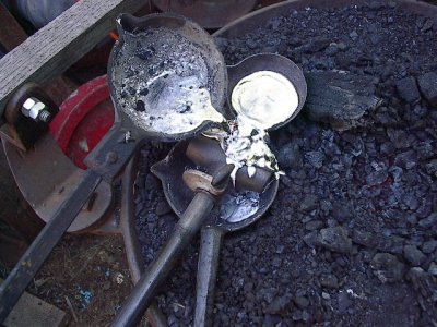
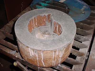
Now we need to look at the common parts of the hammer mold. Not all molds are the same but they should be fairly close. a. ladle bowl b. sprue c. gate d. mold vent e. parting line f. mold clamp g. thumb screw h. upper mold half i. lower mold half

You can melt lead on the forge in a ladle just fine. When I make a lead hammer I like to melt the lead in a separate ladle rather than the ladle on my hammer mold. The reason why is the ladle bowl on my molds are just barely large enough to fill the mold. You also want to use a ladle that is at least 1 to 1 1/2 lbs larger than the hammer your pouring. The reason why will be apparent later.

The first thing you need to do is get a handle made for you hammer. I'll use an 11” piece of 3/8” black pipe. I'll heat the end up and use my 3/8” spring fuller to swage the end of it down, about 3/8” from the end. Fuller it down to where the end is closed. This locks the handle into the head.

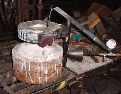
The first thing you need to do with the mold is make sure no dirt or foreign objects are in the mold cavity, vent hole, or gate. Then open the mold, place the handle with the swaged end into it. Make sure you have the handle in so the lead will fill the swaged area, but also allowing the end of the handle to be completely enclosed inside the lead. Close the mold and lock the clamp with the thumbscrew, being careful not to move the handle. Make sure the mold closes all the way along the parting line.

Now get your ladles lined out on your forge. I like to pour over an extra ladle so no lead gets into the coal in the forge. If some does, let it cool and set it aside, to be melted down later into an ingot of excess lead. I like to scrunch my melting ladle down into the fire so it won't tip. You might have to use some thing to block the handle up. Do the same with the extra ladle also. Don't worry if some coal gets into the lead as you melt, it'll float and can be disposed of later. If all of the previous steps are done go ahead and place some lead into the ladle. Try to get all you can into the ladle. This is where nice clean lead is nice. I cut my big ingots in half, which gives me about 2lb chunks.

To melt the lead I'd just give the forge small amounts of air. We're not forge welding, and with the ladle scrunched down into the fire we have plenty of surface area getting hot.
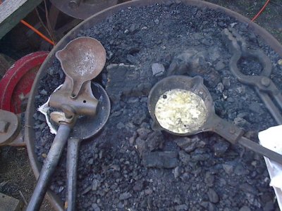
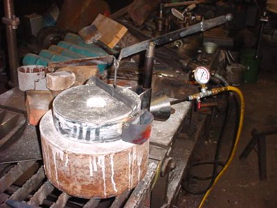
Now as the lead is approaching readiness, get your hammer mold and set it over your extra ladle like so. You may want to slightly pre-heat the hammer mold, but not too much. Look at the lead and use a warm steel rod to stir it. It should be a very liquid state all over the ladle.
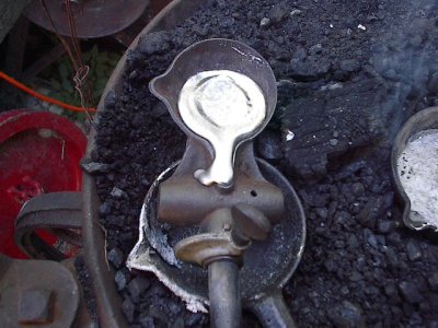
Now what I do is as I pour the lead into the mold ladle, I get it about half full of lead and then tilt the mold handle down, to start the lead pouring into the mold. I continue pouring lead from the melting ladle into the mold as I go. If your lead isn't hot enough or the mold is cool, this is what will happen. This is called a “freeze”. I did this on purpose to show the results.
At this time you need to start over. But first you need to clear the freeze like so. After you get the gate cleared you may have a partial hammer molded. You'll need to open the mold and remove the handle and any lead inside. Since it's hot just stick that end back into the ladle with the melted lead and it'll melt off shortly. Redo all of the pervious steps and try again.
I've also found if you have a freeze like that. You can take the extra lead you have in your melting ladle and go ahead and pour it right into the location of the gate, while you have the mold over the extra ladle you can actually melt the freeze and continue to pour a hammer, although you run the possibility of a cold shunt or weak point in the hammer head. I've got a hammer I keep on my truck and I did this and ended up with a creased looking affair in it, but decided to try it and see how it worked. I've not had any problems with it, and I've used it severely and not had any problems. It's your decision if you want to do this or not.
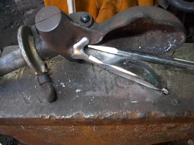
After you pour a hammer you need to wait a little while before you attempt to remove it. You can wait until it's completely cool or if your pouring more than one, you can wait about 5 to 10 minutes before you remove it. I open up the clamp and the lower mold half should open easily. Then I place the mold with the ladle bowl down and use a rod, placed right on the hinge to hold the mold down as I pull up on the handle of the hammer. Remember the vent and the gate are being pulled through their respective openings so it can be hard. Lay the hammer aside gently to cool, if it is still hot.

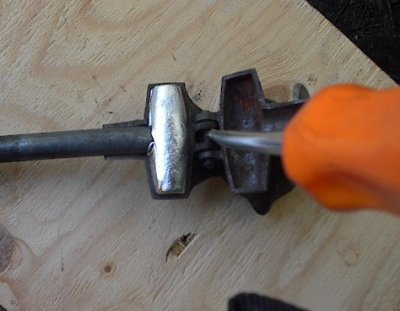
This is what you should have. Next we'll clean the lead sprue and vent teat.
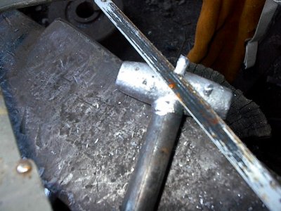
If you have excessive lead sticking out from the gate opening and vent, you can use a hacksaw to trim it close.
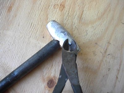
Or you can use a pair of side cutters to trim them close.
Next I use a lead file to smooth any roughness off from the gate and vent area. -
IForgeIron Blueprints
Copyright 2002 - 2007 IFORGEIRON, All rights reserved
BP0273 Mini-Forge
by Steven Walker
Supplies needed to build: 10" long piece of pipe (I used 6" ID 1/4" thick) 2" long piece of 3/4" ID pipe steel plate Ka-wool (1" thick) thin firebrick MAPP gas torch with hose
I had the need for a small portable forge that could be easily transported and built for very little money. I have a camp on the Pearl River in Mississippi and wanted to be able to hammer some iron while there but didn't want to go to the expense or trouble of building a second full-blown forge. I already have a gas forge built from a Freon tank but it is permanently secured to a rolling cart in my shop and would not be easy to transport. And I wanted to be able to quickly pick a forge up, throw it in the back of the truck and go so I needed a forge that was very small, lightweight, easy to build and cost very little. I looked at several designs and including the bean-o-matic but it seemed just too small. I needed something a little larger. Please note that I got the idea for this forge from Larry Zoeller's web site so I want to give due credit to him for this design.

First thing you need to do is weld the plate on one end of the pipe. I used an 8"x8" 1/8" thick plate because I had it laying around the shop. I decided not to cut it down smaller because the excess on the bottom would be used as a foot for the back of the forge. I place a brick under the front to support the front. You could fabricate legs, but the brick works good for me. Next you need to drill a 3/4" hole in the big pipe halfway from front to back. I oriented this to be about 22 degrees from top. Then weld the 3/4" pipe over the hole you just drilled in the big pipe. Next drill and tap the 3/4" pipe for the thumbscrew so that you can secure the MAPP torch head when in use.
Now that the mini forge is mocked up, measure the circumference of the inside of the pipe and cut the Ka-wool to match to line the inside of the pipe. The easiest way to get the Ka-wool into place in the pipe is to roll it tight, insert it into the pipe and and then relax the roll. Then measure and cut another small, round piece to line the plate on the back, inside of the forge. Next measure the width and length of the floor of the forge. Cut the firebrick the width and length necessary and place inside forge to be used as the hearth. I used a tile saw that I had on hand to cut the firebrick but you could use a circular saw, miter saw grinder with proper blade. As an option you could coat Ka-wool with ITC-100 to help hold the heat, but I haven't seen the need in the little forge. I had everything on had for this project in my scrap pile except for the MAPP gas torch. I purchased a Bernz O Matic model # JTH7 MAPP gas torch at my local Ace Hardware store for about $30. This kit comes with the MAPP gas cylinder torch head and hose. Having the hose let me hang the bottle nearby and only mount the head in the forge. Also see Pic1. Without the hose, I would have had to fabricate some way to hold the bottle on the side of the forge when inserting the head in the 3/4" pipe. For this reason, I opted for the torch head with hose. These can also be found at Lowe's, Home Depot and some Wal-Marts.
As you can see, the little forge get pretty hot. I was able to heat and bend a railroad spike fairly easy. To help hold the heat, I placed a couple of firebricks at the front to open and close the forge opening as needed.
The spike twisted.

One more thing you could do that I haven't done yet is to cut a hole in the plate in the back of the forge so that you could push longer stock through the forge to heat farther down a piece of stock.
The spike knife a little farther along.
This forge serves me well for the purpose intended. When not being used, I can remove the torch head from the forge body and and it stores easy. It is light and can be moved to other locations really easily. To set up, all you have to do is insert the torch head in the side of the forge body, tighten the thumbscrew and light the torch. After a couple of minutes, you are up to forging heat.
-
IForgeIron Blueprints
Copyright 2002 - 2007 IFORGEIRON, All rights reserved
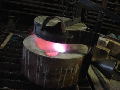
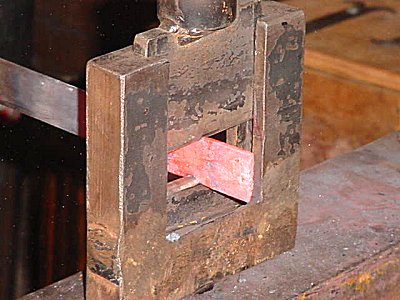
BP0272 Constructing my Gasser Firebox
by Jr. Strasil

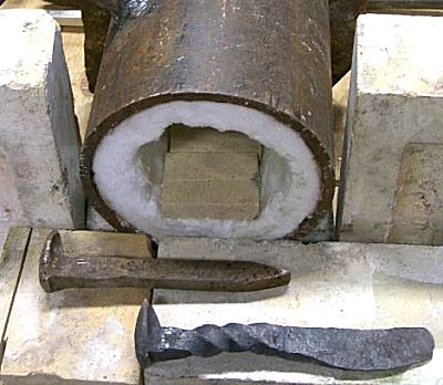
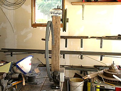
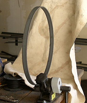
Scrap 1/8 by 6 flat rolled into a 12 and 3/4 OD ring, with tube for inserting burner nozzle.
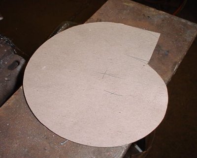
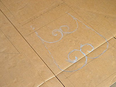
Cardboard pattern for fire chamber.

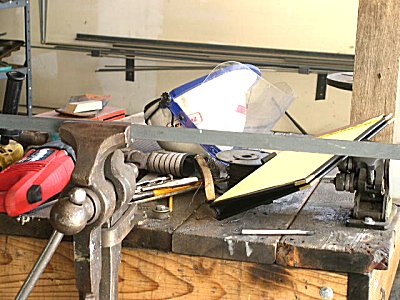
Metal form for fire chamber.
Bottom cut from old barrel top and skip welded on bottom, and fire brick laid in bottom and 3000+ degree refractory poured in.

3/16 by 2.5 inch flat rolled into containment for top with 3/8 Stainless Steel rods attached to hold refractory in place. (Note) black iron will eventually get hot, scale and expand and push refractory apart.

Refractory poured in, with a piece of plywood sprayed with WD40 as a release agent, and a piece of 1.25 pipe set in the center as an exhaust for dragons breath.
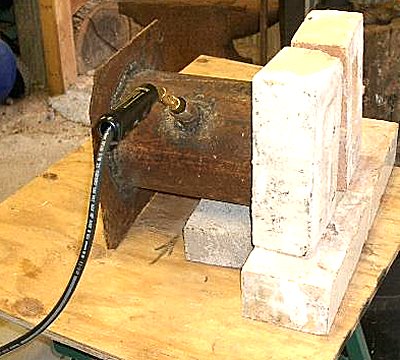
Refractory dried, forms removed and operating handle for top and burner installed ready for firing. Also a small tapered opening for insertion of work cut out on side of bottom.
Top closed and swinging deflector for dragons breath installed on side of top.

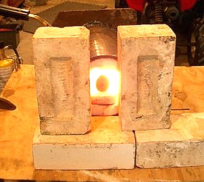
Initial firing at about 1.5 to 2 psi gas to cure refractory slowly.

Same picture without flash.

Picture with no flash, showing Dragons Breath, with first piece of stock inserted.
After 10 minutes at 5 PSI Gas.

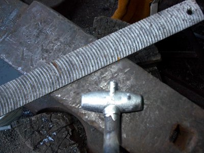
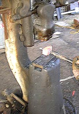
Lid to the side showing heating 2 hammer billets, one 2 lb and one 1.5 lb to make hammers from. About 10 psi Gas and 10 to 12 minutes time. -
IForgeIron Blueprints
Copyright 2002 - 2007 IFORGEIRON, All rights reserved
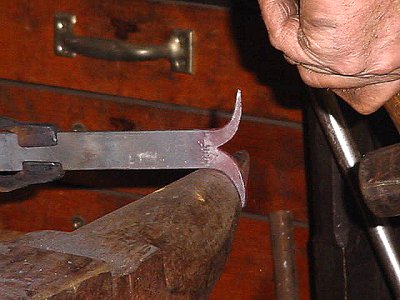
BP0269 Hardie Hole Spacer
by Bob Elliot and Glenn Conner
If you are working on two anvils with two different size hardie holes, many times the quick way to make things work is to make a spacer - not a new anvil tool.

Take a piece of angle iron that will fit into the large hardie hole.

Cut it 1 inch to 1-1/2 inches deep at the fold.

Put it in the vise and bend both sides of the cut away from the inside of the angle.
Now all you have to do is to slip it into the hardie hole.
And your anvil tool with the smaller hardie post will work on the big anvil with the big hardie hole.
Another way to do the same thing is by using a piece of tubing and flaring the top edge a bit so it does not go into the hardie hole.
And yes, the photo is a bit strange as that is a 3/4 inch hardie hole on the anvil and a 1 inch piece of tubing. But is was taken this way to show the difference in sizes.
-
IForgeIron Blueprints
Copyright 2002 - 2007 IFORGEIRON, All rights reserved
BP0268 Unconventional Hinges for a Small Box
by Irnsrgn, photos by Cheryl McDowell
I made another small box for the tooling I keep making for my guillotine tools instead of putting them all in a larger box that would be to heavy, and decided to make the hinges for this one and later make a set for the other one to match.
They are unconventional because they are made of 1 x 1/8 strap and were to narrow to cut and hinge like normal hinges, so I just set them side by side and put a rivet thru them and bradded the ends a little.

Shown are my right angle guillotine dies. I will be using them twice during this blueprint for different purposes, and with another top die.

I started with 10 inches of 1/8 by 1 flat and taking a short heat on one end I am using a 1/4 inch top fuller die with the bottom V die to start rolling the very end of the strap.
This shows the second forming bend on the end of the flat.

Finishing the initial rolling of the hinge eye with a hammer.
The initial roll worked down and the deflection from hitting on the end flattened.
The second heat with a 1/4 inch drift driven in to finish making the eye round.

Working the eye into a nice round shape with a 1/2 inch bottom swage.
Tucking the lip under using a half penny scroll end bottom tool, the 1/2 inch groove is shown being used with the 3/8 groove to the left side.
A view of the 3/4 and 1 inch grooves.

The almost finished hinge eye, I will run a drill bit thru it after it cools so the pin (rivet) will move freely.

The right angle top die in the guillotine to make a short right angle bend.

Finishing the bend over the edge of the anvil.

What the finished end looks like.

A V is cut out of the other end and then worked over the horn to curve and spread them out into a pleasant curve.
Finishing the horns at a red heat over the horn.
Flattening the horns.

The finished rams horn end. I will make 2 more of these all the same, and 2 short ones without a 90 degree bend.

2 each 1/4 inch holes are drilled in each piece and a 1/4 inch rivet is put in each pair, 1 right and 1 left pair and then short truss head screws are put in and tightened up with the nut almost flush with the inside.

A short piece of 1/4 inch round has both ends bent 90 degrees and then bent in the center to form the top part of the hasp and is worked into the eye while hot. as shown.
Using 1/2 inch top and bottom fuller dies to neck down the end of another piece of 1/8 by 1 flat.
What it looks life after being fullered and flattened.

Starting to draw the end down to 1/4 inch wide by 1/8 thick.
Further along with the drawing out.
I lost 2 pictures, but it is now drawn out and bent at a 90 using the guillotine dies.

Short nose scroll tongs and a piece of pipe laid out to roll the end with.

A heat is taken, and the tang is rolled around the pipe using the scroll tongs.
Straightening and flattening the formed tang.

A side view of the tang after forming.

The tang shown after being measured, cut off, and the end pointed and installed on the side of the box. The tang is just long enough to clinch the inside over a little. The loop part has a sharp tapered end that goes thru the wood of the box instead of using 2 bolts and going to the trouble of welding or riveting a loop on.

Showing the finished hasp with the flipper down over the formed tang. -
IForgeIron Blueprints
Copyright 2002 - 2007 IFORGEIRON, All rights reserved
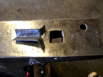
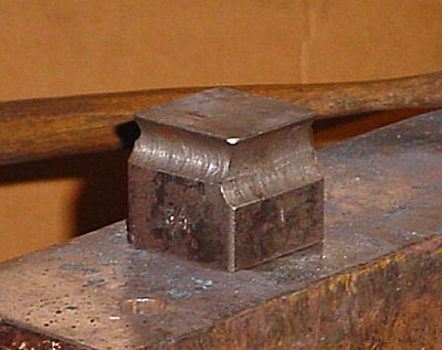
BP0267 Collars, Half collars, or Clips
By Strine, HWooldridge, Irnsrgn, Ten Hammers, Frogvalley, Rantalin, 6013, Ed Thomas, B.H., and Jim Carothers
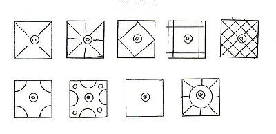
The following question was posed on the IForgeIron Blacksmith Forum. This is the finished product needed. What are different ways to get this accomplished?
How would YOU go about making a dozen of the items?

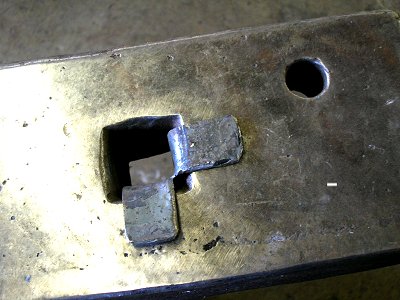
Then....for a one off... open the vice jaws to a little more than 3/4" ... heat up about 2 1/2 " of 1" x 1/8" ... lay centrally across open vice ... lay a piece of 1/2 x 3/8 over the vice gap and hit it into hot piece. hit down until top of 1/2 x 3/8 is flush with top of "wings" avoid squashing wings ... while still hot remove collar to the anvil and tidy up, leaving the insert in place ... trim to length. ... For eleven more repeat.
Some questions first dear client. Those sharp corners at the bends, do they have to be sharp? Let's say no.
The time taken to design and manufacture a handy little Hat Collar tool would be better spent making the other eleven collars. Strine
I'd weld two pieces of 1/2" square to a bit of plate with the right distance betwixt them then make a top tool (also out of scrap) that fit the inside dimensions. Heat the stock, place over the lower jig and swat the top tool with a treadle hammer. HWooldridge
I would just modify the jig I already have for my hydraulic press and go to it, a simple matter of knocking the pieces that are tack welded on off and replacing with the proper size, I used to make something similar 2 at a time, 100 to a run, about 4 a minute in the press. they can also be done on the anvil in a simple jig. I called them clips, they were for attaching the bows on a high wheeled farm wagon. Irnsrgn
Same way I've made them in the past. The collar is 1/4 deep so 2 pieces of 1/4 welded to a piece of scrap, the distance between them about 5/8 or little more (would first wrap a piece of 1/8 around a piece of 1/2 and then weld the 2 pieces of quarter using this distance roughly). I don't have a treadle or a press so I just whack the collar when it's HOT with a piece of tooling made for this purpose and then whack the edges down somewhat afterward (but not a whole lot). I draw the collar ends somewhat to help in closing it fully. Heat the collar Hot, slip it over the place to wrap and then use tongs or channel-locks to close. Worked like a charm the only time I've used them. Ten Hammers
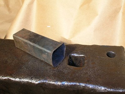
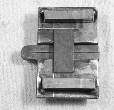
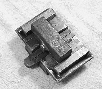
I have a fixture that is set up like a spring fuller. Bottom "die" or swage is shaped just like the collar you have shown and the top is the opposite and fits into bottom with just enough clearance for 1/8 stock. Both top and bottom swages were milled out of solid rectangular bar stock. I welded a piece of round bar to it like a spring fuller, so I could use it under a power hammer or clamp in my vice or press or simply hit with small sledge.
This shape is common for my bolt keepers on sliding door latches/bolts. frogvalley
A jig could be made with two pieces of 1/4" X 3/4" stock that are about 3/4" apart welded to a piece of scrap as suggested below, this would account for the 1/2" width of the collar and the 1/8" of the stock on each side. You can then cut a piece of 1" X 1/8" to 2 1/4" and lay it across the jig, with each end flush with the ends of the 1/4" X 3/4". A piece of 1/2" stock is then smacked into the jig, bending each wing up. The wings are then bent over the 1/4" stock on either side and the angles are all trued over the jig. I drew a picture in paint to help explain what I mean.
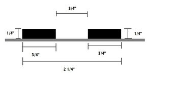
The hard part would be getting the 1/2" bar to be in the exact center of the 1" X 1/8" bar. Rantalin
I am told that this is a "CLIP" and not a collar.
The difference is that the collar encircles and holds 2 or more pieces of metal. A clip is attached to a flat surface to hold a piece of metal or other object in place. Glenn
Glenn a collar is pretty much as your revised description explains....much like that hard bit of stuff at the top of your shirt that goes all the way around your neck. But heh, what you call a rose is what I call a thorny bush that's a mongrel to prune. Who is correct? Strine
Any horse person knows the collar goes around the horses neck and hooks to the harness, the clips go on the clops - the feet. Otherwise the horse could not go clip-clop when he walks. And when the police horse helps arrest a bad guy, it is called a clop collar. 6013
Glenn: Clips are most easily formed with a top tool. It looks like a hand-held swage only instead of round it is square inside. You make it to the dimensions of the outside of the clip, naturally.
To use, place a bar on the anvil that is the size you want for the inside of the clip. You place the hot metal across that. You put the top tool on the bar, and hit it. Simple as that. Ed Thomas
An email I received said these might be called half collars. Glenn
The spring swage equivalent by Frogvalley is a good solution, because it is easier to be accurate. Ed Thomas

This what you had in mind, the top one. Irnsrgn

Click to enlarge


B. H.
Hat-Shaped Collar goes onto a Wall-Mounted Coat Hook.
2x pieces of 1/4" sq. bar 10" long
1x piece of 1/8" x 1" flat bar
2x junk ball bearngs
Lots of heating, beating, punching, and twisting (the bearings are hot punched to let the vertical arms go into about 1/4" for a better joint)

The finished piece by Jim Carothers.
This is an example of how blacksmiths solve problems. There is no "right way" just the way that works for you.
Thanks to Strine, HWooldridge, Irnsrgn, Ten Hammers, Frogvalley, Rantalin, 6013, Ed Thomas and B.H. for working on the problem. All this information was posted on the forum in a 3 day period of time.


This is the rough tooling I used to make a handful of collars. I already had the bottom tool, but it was too deep for the clips I needed to make. Thus you see a spacer bar in the bottom tool. Thanks to all who helped answer my questions. Jim C.

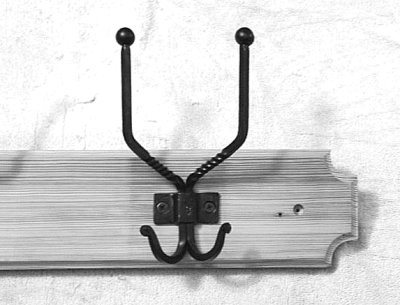
Here are photos of an item that will be in the Saltfork Craftsmen Annual Conference Auction. The yellow pine came from an old house (built around 1900) in Eastern Oklahoma. Even though you can drill and tap this wood, it still finishes out nicely. One of my co-workers donated the wood. The mounting holes are 16" on centers. -
IForgeIron Blueprints
Copyright 2002 - 2007 IFORGEIRON, All rights reserved
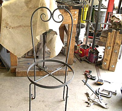
BP0266 Building a Chair
by Richard Hanson
Lay out a full sized diagram of the chair on cardboard.

Using a seamstress tape measure I measure the length of the pieces and deduct the necessary amount to allow for drawing out the points.
Cut 50 ½ “of 3/16” X 1” flat bar to make the ring for the seat. Bevel ends for good weld penetration.
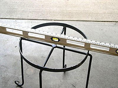
Using ring roller, roll the flat bar into a circle. The inside diameter should be 16”

Weld ends of ring together and grind the weld down flush.
Put the ring back in the roller and roll it again to even out the welded area.
Cut 2 pieces of ½” Round stock 60” long. These will be the base for the seat and the legs.

Mark a spot 3” from each end and score with a punch so the marks will be visible on the hot steel.

Draw both ends of the rods out from the mark to a length of 6 inches

After the ends are drawn to a point, scroll them
Cut a ½” section out of the center of one of the rods and chamfer the ends for better weld penetration
Cut rods butted to the second rod and position for welding. Tack weld then remove magnets and weld solid

Mark a spot on each rod 8” from the center

Position ring on marks making sure it is exactly centered

Weld ring into place
Heat legs and bend 90 degrees
Once all legs are bent, check the seat for level and adjust as necessary
Cut 2 pieces of ½”round stock 40” long.

Mark one end of each bar at 3” from end

Draw out to 6” from mark and scroll ends bend other end to a 90 o offset 45 o
Position back and weld into place

Cut piece of 3/16” X 1” flat bar 18 ¾” long, chamfer ends

Roll into a 6” diameter ring weld ends and grind flush
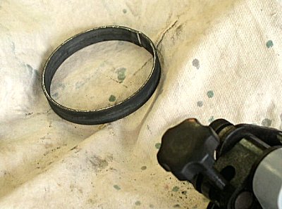
Weld ring and re roll to even out welded area

Cut 2 pieces of ½” round stock, draw out one end of each to a point and scroll, flatten and bevel the other end for a flush fit to the chair back. Position the scrolls and ring, weld into place
Cut 4 pieces of ½” X 1/8” flat bar for the chair leg braces. Drill all in the center for a rivet. Round corners on a belt sander
Flatten ends for a fan scroll

Roll scroll on the end of the bar
All 4 pieces scrolled and ready for riveting

The brace riveted and ready for twisting
Twist as many times as you want, two twists on each side looks good

Weld brace to legs, I picked a spot that was 5 inches from the floor to the center of the brace, but use any distance you want.
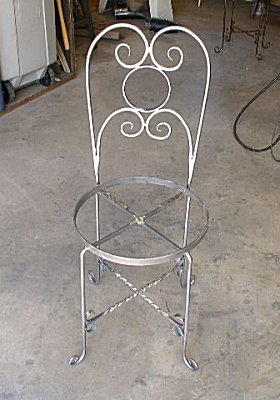
The chair with the welds ground down, and scale wire brushed off, ready for finishing
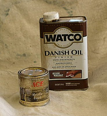
Mix a Watco Black Walnut Oil with a little gold paint to produce an antique bronze finish, the more gold paint you add the lighter the finish will be. The paint does not mix readily with the oil and will want to settle out and clump in the bottom of the container. It is best to use a shallow container and cut the bristles of your brush short so you can mash the paint and keep it mixed. If you end up with a finish that is lighter than you wanted, simply let it dry then put a coat of plain Watco Oil over it to darken it

I used scrap Redwood left over from my deck remodel a couple years ago to make the seat and back. Rip the edges to remove the rounded edge on the boards. Then dowel and glue them together. When the glue is dry sand both sides of the seat with a power sander.
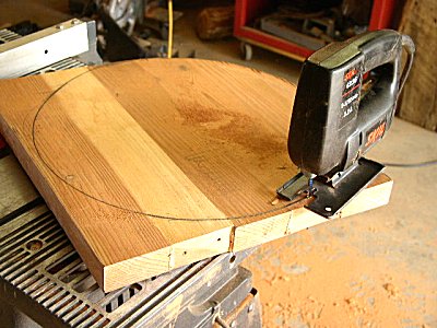
Place the board on the metal seat ring and mark the outside circumference cut out seat with a saber saw. Use the belt sander to finish shaping ring and remove saw marks. Then
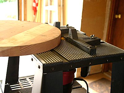
Use a ¼” Round over Bit in the router to round the edge of the seat. Then use a straight cut bit to remove enough stock from the under side so the seat just fits inside the ring. Drill the cross braces under the seat and secure the seat with 4 drywall or deck screws. Drill the seat back ring in 3 places and secure the seat back with 3 long deck screws.

Apply a couple coats of Spar Varnish to the seat and back. Sand lightly between coats and if you want rub out the final coat with pumice and oil.

The finished chairs and table
-
IForgeIron Blueprints
Copyright 2002 - 2007 IFORGEIRON, All rights reserved
BP0264 Measuring Things
by Glenn Conner
When measuring a piece of stock you need to know what length to cut. Put the end of your "ruler" at the starting point. At the other end of the distance read the marks on the ruler. Take the ruler to work table and place it on the stock, transferring the information, then cut the stock. Now take the stock back to your project and make note of how short the cut stock has been cut. Now back to the work table and cut another piece to fit.
You can measure in Biblical cubits, survey rods (16 feet 6 inches or 1/4 of a chain), survey chains (66 feet) or any other standard of measurement you desire. In school, I was taught to measure by using a ruler with imperial units, feet and inches. They expected you to figure out what all those little lines meant and work in fractions. For those of you using the metric system be thankful, your system of measurement makes sense.
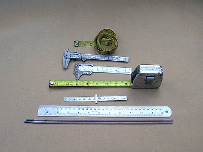
These are a few of my favorite tools. Sewing tape, 6 inch vernier, 4 inch vernier, 16 foot steel tape measure, 6 inch steel ruler, 12 inch steel ruler and welding rods. For longer lengths gas welding (oxygen/acetylene) rods are also used.
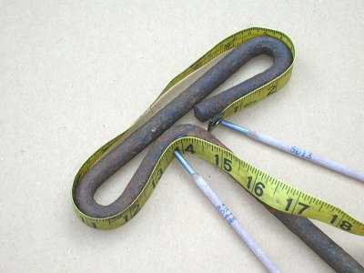
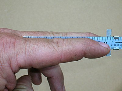
The sewing tape is a fiberglass or plastic flexible ruler. It comes in real handy when measuring curved surfaces. This example is how much stock do we need to make a handle. One word of warning, the tape measures the OUTSIDE and INSIDE of the curve. To get things more accurate you need to measure the middle of the stock to get a length that is closer to what is actually needed.

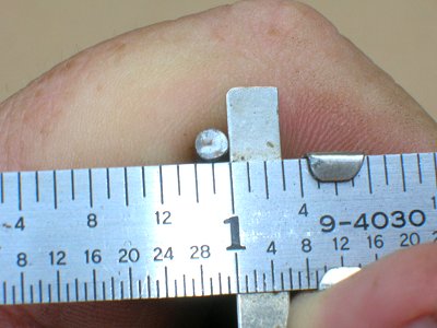
The vernier is a neat tool that will measure in 1/16th of a inch or 1/32 nd of a inch and some even more accuracy.
In this example a AA battery is 9/16 inches diameter, or 18/32ths - which is 9/16ths. That is also a good thing to remember when in the field and there is no ruler handy.
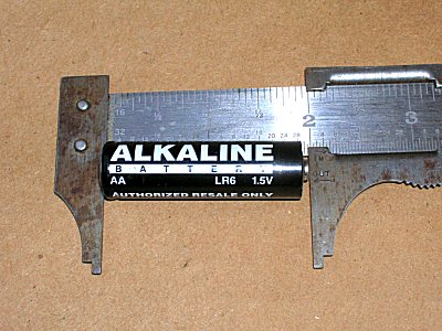
The vernier measures the AA battery at 2 inches long. Another good number to remember when a ruler is not available.
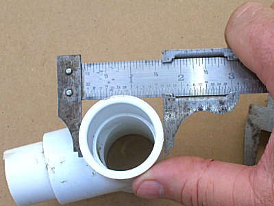
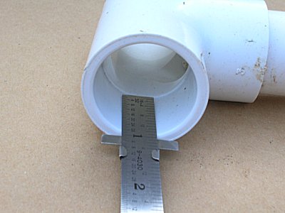
The vernier measures the outside diameter of this plastic pipe fitting at 1-5/8 inches diameter.

The vernier measures the inside diameter of the pipe fitting at 1-1/8 inches. CHECK MEASUREMENT
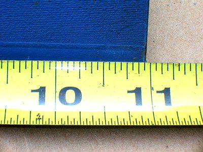
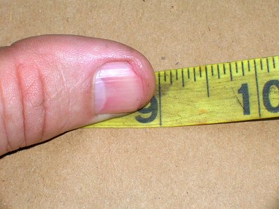
The 16 foot steel tape measure is reasonably straight forward, put the hook over the end of the object to be measured and extend the tape. Then read the distance, in this example 10 and 15/16 inches.

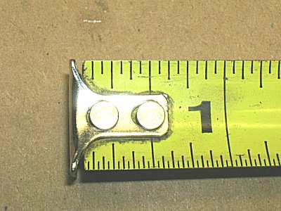
Look at the two photos real close and you will see that the hook of the tape is riveted onto the steel tape and the rivets are LOOSE, allowing the silver hook to move.
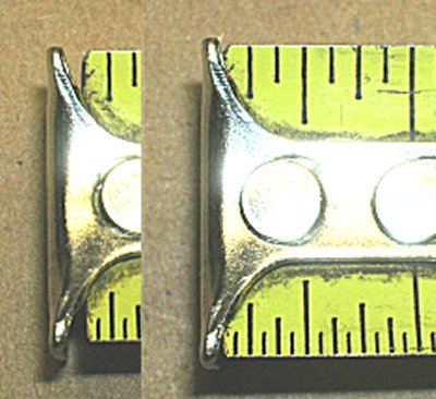
This photo shows the length of the movement a little better. The reason for this is when you do an outside measurement the hook moves longer to the "zero" position on the tape. When you do an inside measurement, the hook moves shorter to the "zero" position on the tape. The difference takes into account the thickness of the hook.
The 6 inch steel rule can measure in 16ths of an inch or in 32nds of an inch and has a sliding depth gauge that also doubles as a pocket clip.
When you use the depth gauge, be sure and get the proper alignment at the start. The depth gauge is to the left of the 1 inch mark here.
Properly aligned to the 1 inch mark, you can then read the rod as being 1/8 inches diameter.
The ruler is quick for reading the depth of the socket in this fitting.
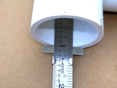
The depth is 1 inches.
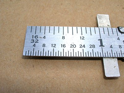
The 12 inch steel rule is divided so you can read 32nds of an inch and the end is cut flush to the zero mark.
The area between 3 inches and 4 inches is divided into 64ths of an inch in case you want to get just a little closer to right. Notice that 1 to 3 inches is in 32nds of an inch, 3 to 4 inches is in 64ths of an inch, and 4 to 12 inches is in 16ths of an inch.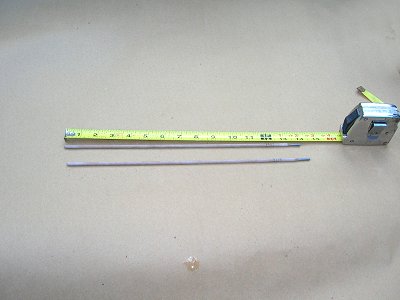
A lot of times we have welding rods laying about.

They just happen to be 14 inches long. A good number to remember.
Line one end of the rod up with the end and mark the rod at the measurement needed.

It doesn't hurt the rod and the rod can be used for welding later.
It is real easy to tell the length required when you get to the work table, but oops, which side of the line is the correct length ?

I fix this by putting an extra mark or dot on one side of the line. In this case, the dot calls for the left side of the line to be left when the cut is made. The X calls for the line to be split with the cut.
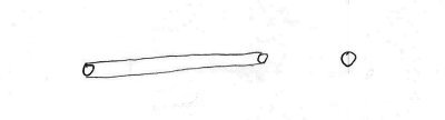
If you have an inside measurement longer than your ruler, I tape two welding rods or oxygen/acetylene welding rods together and mark them across both rods in case the tape slips.
This over lap is unimportant as it is the end to end dimension that is the inside dimension of our project. What is that distance? Who cares, it is whatever the length of the measurement is equal to and does not require dimensions.

I have learned that I carry a tape measure of sorts with me most of the time - my hands.

Across the knuckles is 4 inches.

Hand and thumb is 7 inches.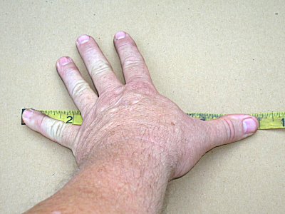
Hand span is 9 inches.
These are good numbers to remember, 4,7,9 and any combination of two give you a wide variety of numbers to work with: 4, 7, 9, 11, 13, 14, 16 and 18.

The thumb at the first joint is 1 inch wide.
The depth of the first two fingers is 3"

You also need to be careful because 1 inch wide masking tape is 1 inch wide, but 2 inch duct tape is only 1-15/16 inches wide. Sometimes you just need a ruler to tell the difference. Did you know that a penny is 3/4" in diameter.
I have found, more than once, that rulers are not accurate when compared to each other. If anything is critical always use the same ruler you measure with to measure the cut. Let me suggest another (better?) way to use that ruler. Measure as before by putting the end of the ruler at the begriming of the measurement. Read as before but this time do not combine the fractions. For instance 7-15/16" is 7 + 1/2 + 1/4 + 1/8 + 1/16" and a bit long to remember. By adding all those fractions together and arriving (hopefully) at 7-15/16" there is a good chance of making a mistake. Now to transfer the measurement of 7-15/16" to a piece of stock you have to break the measurement back down into the fractions again to arrive at 7 + 1/2 + 1/4 + 1/8 + 1/16" and then make your mark.
Breaking the measurement down adds another chance for mistakes. Why not just leave the measurement as you first read on the ruler 7 + 1/2 + 1/4 + 1/8 + 1/16". Although it is a bit long, there are two less chances of getting it wrong.
Many things are divided into half. So divide the original measurement in half 7 + 1/2 + 1/4 + 1/8 + 1/16" = 3-1/2 + 1/4 + 1/8 + 1/16 + 1/32 and make your mark.
But why go through all than when you can read the ruler the "other" way. 7-15/16 is also 8" - 1/16". It is real easy to mark 8 - 1/16" on the stock.
An easy way to find the center of a piece of stock is to balance it on the hot cut. A whack with a hammer will mark it just enough to keep the measurement.
How many of you had problems figuring out that the rod was 1/8 inch in diameter. To figure that out you had to read the ruler in reverse and you did it without thinking. Why not use that trick to your advantage?
Measure twice cut once .
Measure with a micrometer
Mark with a crayon
Cut with an axe
The width, length and thickness of the pack of cigarettes can be used as a ruler. It is a "standard" size and handy when needed. Just be sure to use the same brand and type cigarettes if you give these measurements to someone else. Leah Fuller
Use your anvil as a ruler, The face has width and length, the horn a length, heel to near side of the hardie hole, heel to far side of the hardie hole, etc. I looked at my anvil and got 20 different measurements from 1/2 inch to 21 inches.
Get to know your anvil. Measure the face from heel to front edge. Then to edge of cutting table ( these are length measures ). Also, from working side to near edge of hardie hole, far edge, and to both sides of pritchel. Numerical measurement not as important as finished goods ( IE how far to draw the end of a piece for a loop ). Then you can repeat as necessary. Easier for me to write down in the book that I need to draw to far side of pritchel than to a measurement on a ruler.Length measurements handy for hot cutting long hooks at a demo. Just hold the measurement with the thumbnail, transfer to the hardie, nick the stock, and you've got a place to hot cut. You can use 1/2 anvil face length too, and on and on and on.
This ain't machine work, and no need for the micrometer. Same can be said for using the vise ( small hacksaw mark for a specific length, or maybe use both sides of the jaw mount screws, I use both ) as a ruler.
Throat of a pair of tongs works too.
Hammers can be used as rulers. Length of handle, length or width of the head, and so on. Looked at my hammer and got 7 different measurements from 1/2 inch to 13 - 1/4 inches.
Whatever works for you. Write it down, or you'll forget it in 6 months when you want to duplicate something you built today. This ain't rocket science, but may actually be used in repetition for duplication of things needed in large numbers. And faster than using a measuring stick with a marker.
Ten Hammers
-
IForgeIron Blueprints
Copyright 2002 - 2007 IFORGEIRON, All rights reserved
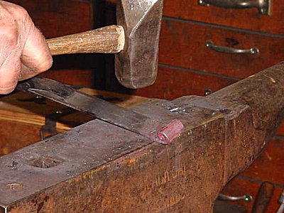
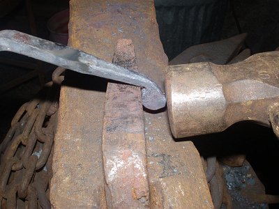
BP0263 Hot Cut Ideas
by Jr. Strasil
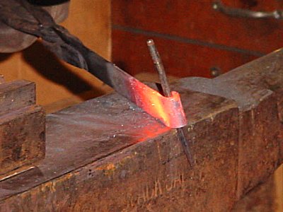
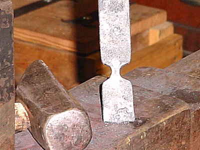
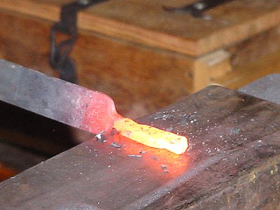
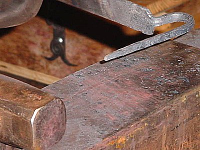
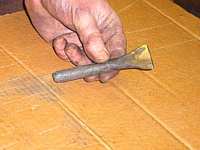
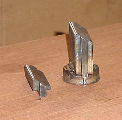
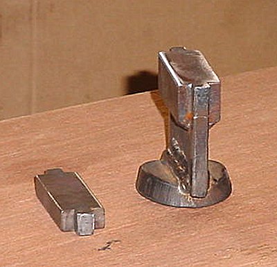
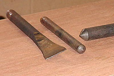
I know many of you use a traditional thin bladed hot cut as I do, but occasionally when striking on the intended piece of hot iron it wants to slip sideways and you have to realign it. In an old book I saw a remedy for this situation and made my own example of it, and it really does work. Just radius the end slightly as shown and then sharpen. It has a tendency to cut into the center of the piece easily and keep it from sliding around when hitting the piece to cut it off.

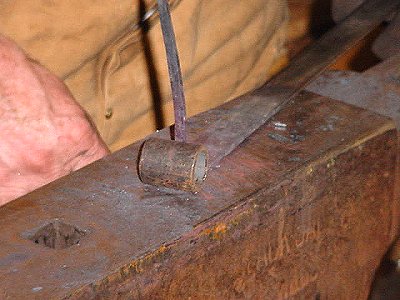
This one was fullered almost thru while hot and then the excess was cut off and it was sharpened from the straight side only. I use it to cut off chisels and punches so that it gives me a nice rounded end for striking on.
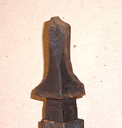
Side View -
IForgeIron Blueprints
Copyright 2002 - 2007 IFORGEIRON, All rights reserved
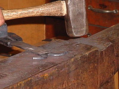
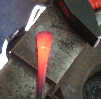
BP0262 Fire Strikers
by Ralph Douglass
Tonight I will try to show how I make fire strikers. (The Steel part of Flint and Steel Fire Starters.)
I start with about 5 to 6 inches of garage door spring, the round coiled stuff. Of course you need to pull it straight first before cutting to length.
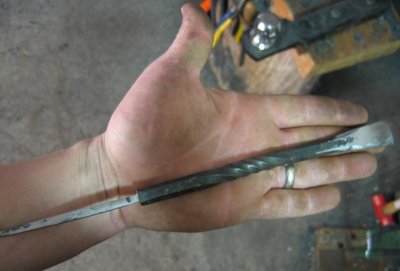
Heat steel to working temp insuring you do not get it too hot so you do not ruin it. Now slightly flatten the piece, but DO NOT thin it too much. The leading and trailing edges will be slightly curved. You want this.
Re-heat it and then taper both ends slightly. And in same heat make a small scroll on each end. Make sure scrolls are facing the same way.

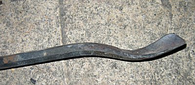
Heat again ( with practice you should be able to drop one heat or so). Now once hot, bend into a slightly elongated C shape.
Now straighten the long edge carefully.
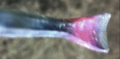
Now have a can of water ( I use a 3 lb coffee can for this) heated to about 180 F. Also heat the striker to the critical temperature ( non-magnetic) I use refridgerator magnets for this, and have one hanging from baling wire near the forge. Bring the stock to the magnet not the other way. When the magnet is no longer attracted to the hot steel, you have reached the critical temperature. Once it is at critical temp then quench the long edge about half way up the arms. Once the edge is cooled below critical dunk it all til cool.
Now you need to clean scale off the striking edge. I use a piece of hard red brick and rub off the scale and get it more or less shiney. Use what you have. It is not needed to be a mirror, just no scale as that will prevent spark formation.
-
IForgeIron Blueprints
Copyright 2002 - 2007 IFORGEIRON, All rights reserved
BP0261 Portable Anvil Table for Demonstrations
by Irnsrgn
Jim - C asked me for details of the table I use in front of my anvil when doing demos, I took it to OK when I went down to see Jim. I have a bad back and so don't like to put tools on the ground as I have to bend over to pick them up, and everything is handy right in front of my anvil. So here goes.
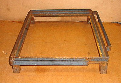
I started with a 1/8 by 1 1/4 angle iron frame 18 by 24 inside measurements. I put 3/16 flat bar on 3 sides to hold hardy tools, tongs and other things. The spaces on the right hand corner are where I hang a water can to cool tools off and a can of coal dust to dip tools in when punching and slitting etc.
I used short pieces of 1 1/4 OD square tube with one end cut at a slight angle to give splay to the legs and drilled 1/4 inch holes thru both sides to put safety pins in to hold the 1 inch square tube legs in place.
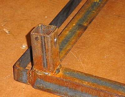
A close up of one of the legs. It was a lot of trouble to cut the tube so it angled both ways so it only angles long ways.

The 4 each 1 inch square tube legs with one end bent to give splay (stability) to the legs sideways and with holes drilled clear thru for the safety pins.

4 safety pins bent out of 1/8 copper coated steel torch welding rod. Yea, I know they are not all the same. LOL

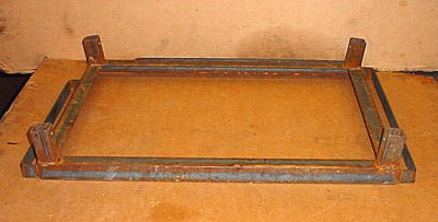
The main frame upside down and the legs installed with the safety pins in place.

The table set up like it would be in front of my anvil. It is very stable and will support a lot of weight.
-
IForgeIron Blueprints
Copyright 2002 - 2007 IFORGEIRON, All rights reserved
BP0260 Veining Tool
by Irnsrgn
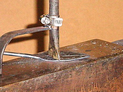
When veining leaves etc. I sometimes had trouble keeping the object to be veined steady on the anvil surface, so I made this little universal holder to hold a variety of punches and veining tools. I call it my 3rd hand tool holder.
The first thing to do was to make a veining tool with a shorter shank as most of my chisels, punches etc. have 8 inch long shanks to keep my hand away from the heat. This is a side view of the tool.

An end and side view of the tool, it has a 1/16 radius on the end.

Next was a spring holder to fit in the hardy hole made of 1/8 by 1 flat iron.
A view from the other end showing the punch holder which is half of a piece of black pipe welded on.

A small hose clamp used to test the tool with. I didn't want to spend a lot of time making a real secure clamping system till I was sure it was going to work.

A view of using it for the center vein in a leaf.

Veining the right side of the leaf.
Veining the left side of the leaf.

What it looks like now with a more secure and easily changed clamping device.
-
IForgeIron Blueprints
Copyright 2002 - 2007 IFORGEIRON, All rights reserved
BP0259 Wall Hook
by Jr. Strasil
Little items seem to go over good at different places especially when the customer has a variety to choose from, these little hooks can be attached with one counter sunk screw and are relatively easy to make. And most people will take more than one sometimes as many as a dozen.
LITTLE DECORATIVE WALL HOOK by irnsrgn
These are my round nose side set or side fuller dies for my guillotine tool, a set of narrow 1/4 inch or 3/8 fuller dies will work as well. This set has round noses as for this type of operation a sharp edge will leave you with a cold shut that will break off as you work it.
3/16 by 1 inch flat iron being fullered a sufficient distance from the end to leave about a 2.5 to 3 inch tang 1/4 inch wide, 3/16 thick and tapered on the end.

A little farther along with the fullering, and a picture just to add a note to be careful when doing an operations such as this, keeping rotating the piece as you fuller as the top will always go deeper than the bottom, so I rotate every second or third blow to prevent this from happening.
This is what you should end up with after fullering or side setting.
These are what I call my Set Hammer dies for working close to a shoulder.

The set hammer dies i use after drawing with the right hand quarter peen hammer, these dies allow me to work the thickness and width easier, and then the very end of the tang is tapered with a hammer.

This is what it should look similar to at this stage.

Using a hardy that has all the taper on one side and a piece of 1 inch flat for a gauge, I am cutting a little over half way thru the main part, this allows me to have a nice handle to work with and I am sure of a 1 inch square end to use for fastening and decorating.

With the cut up I am punching a 3/16 hole in the center of the square part. If you cool your punch and leave a drip of water on the end then flip the part over and place the punch on the spot that shows it will cool the thin piece left and when you hit the punch it will shear it out rather than just push it thru and stick.

Counter sinking (chamfering) one side of the hole over a bolster for a countersunk screw. The bolster keeps the point of the tool from hitting the anvil face and also keeps the metal from deforming to the other side as it needs to be flat.
Using a veining tool with a 1/16 round nose to put the design in the piece.
The veining tool and a 5/8 and 7/8 countersink tools.
What it looks like with one more vein or decorative mark to be put in and just prior to being broke off in the vice at the cut and filled smooth.

Rolling the rat tail end toward the back side of the piece.

Rolling the hook around a short piece of pipe with the scroll tongs.
After painting lightly with a brass brush and propped up with a square nail to show the front.

A diamond shape with a different design. This one is used to hang some of my smithing tools on.

One with the hook sticking out instead of rolled around to hold more stuff on, and it has a different design stamped in.
Just a few of the many designs for the veining that are possible.
-
IForgeIron Blueprints
Copyright 2002 - 2007 IFORGEIRON, All rights reserved
BP0257 Bending Fork
by Bob Elliot and Glenn Conner
Thanks to Bob Elliot for this great idea. He was always out of position with the bender and this was HIS solution to the problem.

Ok, you need a bending folk. Grab any round piece of stock, fire up the forge, and bend a "U" shape

While your at it make 2 "U" shapes. Thing of it like a big "S" hook.

Now instead of the usual weld the "U" on the end of a bar, weld one "U" perpendicular to the other.

This way you can bend or tweak easily as usual.
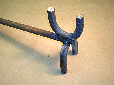
Or flip the tool over and now bend or week the "other" way.
The round bottom has a tendency to make flat iron deform and twist so be careful to stay at the ends of the feet. Or make one with a sq bottom.
Thanks to Bob Elliot for this great idea. He was always out of position with the bender and this was HIS solution to the problem. Works for me too.
-
IForgeIron Blueprints
Copyright 2002 - 2007 IFORGEIRON, All rights reserved
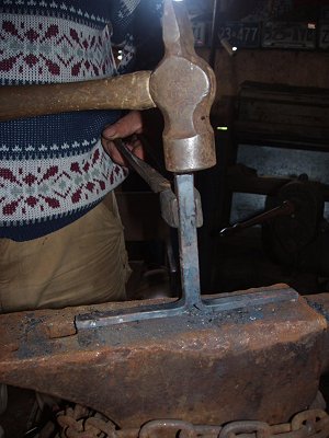
BP0251 Making a Smithing Hammer
by Bill Epps
I started with 3 in of 2 in round 4140. It was squared up, and I roughed out the pein in the power hammer (#50 LG). The mark on the hammer head is for the slitting punch that I use to start the hole for the handle.

This is the slitting punch I will use.
I use green coal in the slit to keep the punch from sticking and letting the punch get to hot you have to keep the punch cool and hot let it get to hot.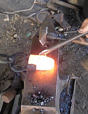
After taking a good heat, start the slitting punch --you have to get the piece good and hot.

Drive the slitting punch about 3/4 of the way through the block from one side, then finish from the other side. I use green coal dust in the hole as a lubricant to make the punch release, remember not to let the punch get to hot or it will deform.
After driving the slitting punch all of the way through the block, then I am ready to use a drift to size and shape the hole so it will fit the handle. I use standard store bought hammer handles.

I made this drift from one inch round bar. I left it long enough to be used for a handle under the power hammer and use anti seize compound as a lubricant.
After driving the drift through the slitted hole (driving it from both sides, top and bottom) so the hole is bell mouthed on both sides, I went to the power hammer. With the thickest side of the eye up, I square up the sides, keeping the thickest side up will bring the hole back to the center.

After the hole is to size and shape, I went to the vice and flattened the face and let the face flair a little.
Now I harden the face and pein of the hammer head, (just the face and pein need to be hardened) the center part including the eye is left SOFT.

After hardening the face and pein and doing some cleanup grinding, I install the handle, tune the hammer handle, and the hammer face, and here is Leah's new hammer.
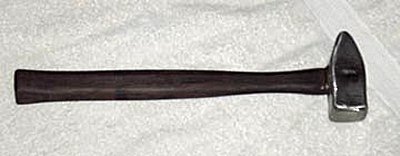
The finished 2 lb. 5 0z. hammer.
-
IForgeIron Blueprints
Copyright 2002 - 2007 IFORGEIRON, All rights reserved
BP0252 Spoon Gouge
by Jens Butler aka Oakwood
It all started this Saturday…
I decided I needed a new dishing stump, I had decided to make some more copper candleholder cups and the old dishing block was split. So I selected a good seasoned Pin Oak stump , sat down with my best German made 1" straight gouge and on the second cut broke out a good sized half moon chip. Cursing and cussing myself for not having the right tool to do the job I set out to make one.
This picture is of the broken store bought gouge and the one I made.
I will be using a US made 3/8 Allen wrench, worn out of course, I like recycling old tools into new ones.

Now to start a fire, I am using a wad of paper and a stick of fatwood, throw on a scoop of charcoal, start the blower on low … and light.

Two minuets later…
Taking a good orange heat ( It’s best to stay away from yellow heat on high carbon steels. A good rule of thumb is: Big flakes of scale - your burning carbon out of the steel, Small flakes of scale - you are safe )
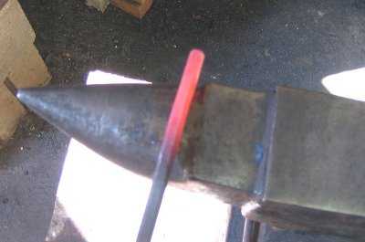
I first straighten out the “ L “ over the horn first and then true it up on the face, sight down it and turn, you want it nice and straight. Keep in mind that this is high carbon steel and by the time I have taken most of these pictures the steel is too cold to hit.

Now I will be forming the tang , using the front “ sharp “ edge of my anvil and a 1000g cross-pein, form a distinct shoulder. Don’t worry over it too much as we will be filing it square later, just keep it sort of even and in the center. Then taper the tang gently.

I took 6 or 8 Heats to do this, as the ”window” were you can hit this stuff is pretty small.

Here is how the shoulder will look after we file it down.
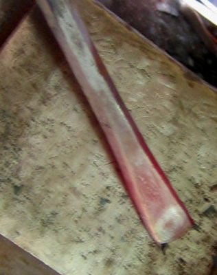
Now its time to start on the “fun“ end. Take a good orange heat and begin flattening out into a fishtail shape.

Take another good orange heat
Widen the fishtail with the cross pein

It should look something like this
Now using the step of the anvil (because I don't own a swage block), begin to make it concave. Just roll and tap, keep it good and hot, too cold and you will crack it. Use the horn to even it out if you get it lopsided, once again don’t worry too much because we will be doing a fair amount of stock removal before it’s all over . At this point it should look something like this. For a straight gouge stop forging here.
For a spoon bent gouge hold the “ blade “ off the back side of the anvil, give it one good tap.

The top view.

Now Place a small ball-pein hammer in the vise ( facing ball side up ) take one more heat and just even out the cup of the gouge. Sometimes I like to put a little twist in my wood working tools, if you want to now is the time.
Now set it off to one side and let it cool slowly, (DON’T QUENCH !!! ) this is a good time for a lunch break or move on to you next forging project, I did 2 gouges, a skew chisel and a RR spike knife in the in-between times. When it is cool enough to handle file the shoulder nice and square.

It should look something like this:

Now on to the blade, As I don’t currently have a working belt grinder, I am doing this the old fashioned way … Files and sandpaper. Smooth out the bottom and the inside of the spoon, for the inside I used sandpaper, just wrap it around a dowel or stick. I then started a 30 Deg bevel, leaving about a 1/16th of an inch un-sharpened. Too thin and it will burn up in the heat treat.
This is what it should look like
If you let the fire die down, re-start it, add a large amount of charcoal, while you are waiting on the fire, cut 2 rings off a piece of ¾” gas pipe
Using ring tongs and the horn of the anvil to size the ring to fit your chosen handle material, red oak is traditional, I however am breaking from tradition and using seasoned birch with the bark still on it.
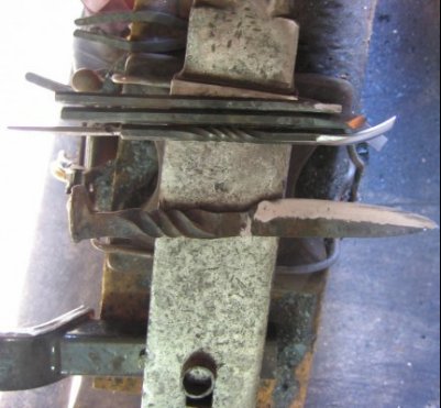
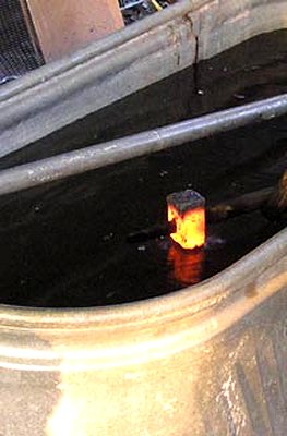
Now that I have a good deep pile of burning charcoal I am ready to start heat treating, I usually do several at once. My oil tank is a large stainless steel stock pot with a lid, one of those cheap-o ones from Wally world. Here are the four items I will be heat treating.

I usually hold at a good cherry ( non magnetic) red for at least 30-60 seconds on something this small, To quench , plunge down into oil, moving up and sown , don't swirl. If it catches fire drop the lid on , it will go right out. To temper something like this I usually heat the "shank" keeping the blade away from the fire, for wood working tools the shank will be blue and the faintest hint of straw bleeding into the edge. when this happens quench again in oil. This is a pic of the skew chisel not the gouge but you get the idea.
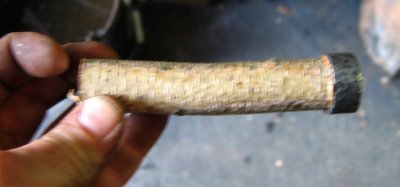
Now for some work on the handle, while the blade is in the solvent tank degreasing (spaying with brake cleaner and wiping with a rag works too). Take the chosen handle material and taper the ends slightly so the hoops will just start to go on. You want them to fit really tight, drive them on with a hammer, on the " striking end" you want the wood to stick up above the hoop 1/8th inch to protect your chisel hammer or mallet from striking the hoop. If the tang of the gouge is 1/4 " square drill a pilot hole 3/16" for oak or 1/8th" for softer woods, make sure the pilot hole is the length of the tang. Wire brush the blade heavily to remove any scale from the heat treat

To assemble, simply drive the the tang into the handle, if you hooped the handle right and drilled the pilot hole big enough it wont split.
I finished with sandpaper up to 320 grit and sharpened on my gouge designated water stones (they have a grove worn in them) I like water stones personally, they seem to give me a better edge especially on harder tool steels. Be sure to soak the water stones for a few hours before you need them, my finish stone is a 2000 grit, no real need to go much further than that on just a wood gouge. Now to try it out! Using a spoon bent gouge is different than other gouges, rather than pushing or hammering you just kind-of pry out the shavings, working from the center out. really works great on tough end grain, just what I needed to carve my dishing stump.

A view of the gouge in use.

A close up view of the gouge in action.
-
IForgeIron Blueprints
Copyright 2002 - 2007 IFORGEIRON, All rights reserved
BP0253 Coat Hooks
by Duck
Evening all, my names Duck so save your fowl comments till the end. Tonight we will be making my version of COAT HOOKS.

I start with 8” ” sq. stock and cut it down the middle for 3 & ¾ “.
Next we will be splitting this cut on the hot cut hardy, and then take it to horn to split them out wide.


After that use a small radius punch at the centre of the split to stop splitting further and to make a place for the button. Ouch! A button is just my way of making the split look better. Cut 1/4” round stock just a little longer than the ½” sq. stock and round both ends.


Finish flattening out the two arms to a T shape.

Square up one arm and draw to a flat point.
Round the end of this arm up about half way back, and square up the rest of the arm if it needs it.


The other arm is next, leave e square on the end as wide as your stock and draw down behind it. The edge of my anvil is not suitable for this so I use a square stake in the hardy hole.
This is the start of my halfpenny snub-end scroll. At this point you should have forged an offset neck. So far the snub-end is still in the same plane as the arm, or the sides are all the same thickness. The finished scroll will be at 90 degrees to this. The button will be a quarter twist from the arm. Round the offset neck just behind the button or square on the end.
With the hot button in the vise give it a quarter twist.
This is the before and after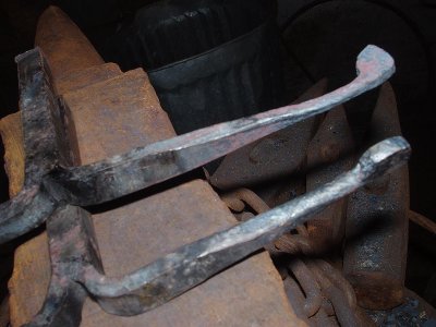
Now square up the offset neck back to square, and all the evidence of the twist disappears. Rounding the button is next. On the flat edge of the stake or anvil set the inside point and hit the outside point of the square on the end of the arm.
If they are difficult to line up bend the button over a little. To get the last point, flip the piece on its back on the anvil and tap the last point in. Dress up the shape if it needs it till its round.

To get rid of the radius between the neck and the button use a curved hardy punch. Set the button on the sharp edge of the punch and give it a sharpe rap.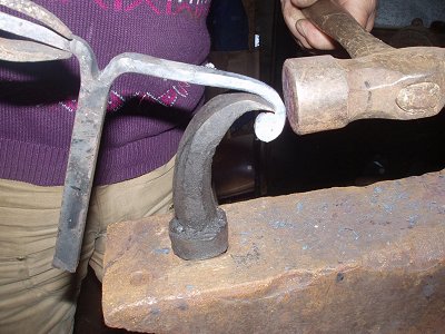
Flip it on its back again and roll it up just a little.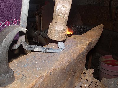
On the end of the other arm forge it to a circle but don t close it completely. This will allow you to slide handles onto the circle.


Take the 1/4 inch round stock button you made and place it in the middle of the hot split and with a blunt punch hammer it into the centre of the split. While its still hot go to the anvil and close up the split.


Now it should look something like this.

To finish up heat the centre and bend the main body 90 degrees so the halfpenny snub-end scroll is the top of the coat hook.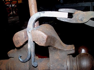
Next take the rat tail and carefully bending it 180 degrees using a half inch mandrill, drawing it past the main body so it can be used as a secondary hook.
The last part to make I call the mounting plate. With a piece of 1/4 inch plate 2” square drill a 7/16 inch hole in the centre.
Square up the hole with a square punch.
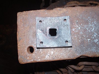
Drill all four corners for 1/4 inch screws with counter sinks
File the four sides of the coat hook base so you have a shoulder to fit into the centre of the mounting plate.
Peen over the end of coat hook on the mounting plate
Mount the hook on a board and hang up your coat.
-
IForgeIron Blueprints
Copyright 2002 - 2007 IFORGEIRON, All rights reserved
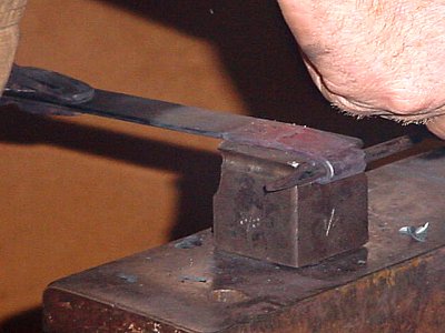
BP0255 Stop the Anvil Ring
by Gerald Franklin
Credit for this device goes to Jerry Hoffmann who publishes “The Blacksmith’s Journal”.

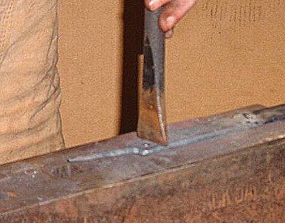
This little item is designed to deaden the ring on European style anvils, as the hardy hole is near the horn. I suppose that it would also work on London pattern anvils, hardy hole near the heel, although I've never tried it.

Take a piece of 3/16” X 1” flat strap and forge a kind of J-scroll with a tight tail that will fit into the hardy hole.

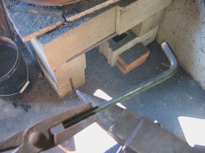
It will resemble a hold down tool and I suppose that it could be used as one, but in this case, it will be driven into the hardy hole from the bottom. The tongue of the strap will rest against the horn to deaden the ring. It REALLY works. Most of my hardy tools can still be used with the deadener in place, but if I need the entire hardy hole, it only takes a couple of seconds to knock it out. -
IForgeIron Blueprints
Copyright 2002 - 2007 IFORGEIRON, All rights reserved
BP0254 Anvil Accessories
by Gerald Franklin
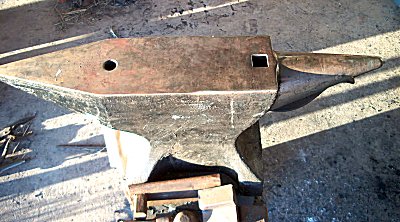
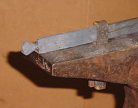
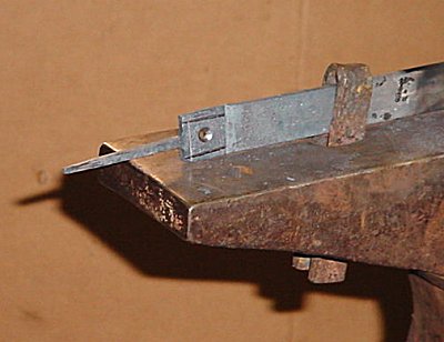
I really like my Czech anvil, but I miss having a step.

I took some 3/4 inch mild steel from the “parts pile” and built one. It’s basically a sandwich with the top slice about 1-1/2 inches to 2 inches shorter than the bottom slice, welded up with 7018 rod and a hardy stem attached.
It looks like this from the side. By the way, I suppose that you could heat the thing and harden it in “Super Quench” but since nothing but hot iron will touch it, I think that’s over-kill. I’m not crazy about Super Quenching welds, even those made with 7018.
-
IForgeIron Blueprints
Copyright 2002 - 2011 IFORGEIRON, All rights reserved
BP0203 Anvil Stand
by Garth of Dropstone Forge
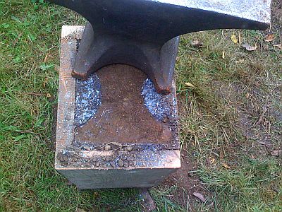
I built a new anvil stand today. My old stand was built of a mess of 2×12s glued and bolted together (see figure 11 on this page). It was unstable on uneven ground and I never felt really good about it. Also, even with a mess of silicone caulk on top my anvil, being an old Peter Wright, rang loud enough to require earplugs. So I built a new stand out of 2×12 by screwing together four lengths and making a box with either end open. Then I filled it full of dirt.
The silver-grey stuff is scale that forms on iron when it's being worked. It then flakes off and makes a mess. I don't know if the resolution is high enough to see the earwig that ran out when I moved the anvil, but it's there.
The silver-grey stuff is scale that forms on iron when it's being worked. It then flakes off and makes a mess. I don't know if the resolution is high enough to see the earwig that ran out when I moved the anvil, but it's there.
I call it my Rammed Earth Anvil Stand on account of I compacted each layer of dirt with a chunk of 2×4 and a sledge. It came out rather well, I think. It’s much more stable than the old one because the dirt inside conforms to the grass and soil it’s resting on. Also, the much greater mass means that my hammer blows move more metal and the anvil doesn’t hop around when I’m working. Best of all, the column of dirt damps the anvil and it’s not so xxxxxxx loud all the time. As a further upside, I can tell the relative temperature of the iron by the changing sounds as the metal cools. Nifty, eh? Also, very cheap.
This is my anvil. You can see the dirt it's resting on. It's like a raised bed for metalworking.
My only concern it that the weight and the hammering will cause the screws holding the whole shebang together to pull out. If this happens, I’ll just run some bands around the outside for strength and hope it holds.
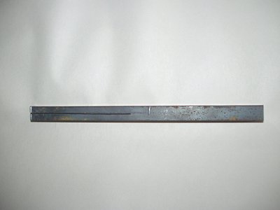
BP0280 Billy Hook, tripod
in BP 200 Series
Posted
IForgeIron Blueprints
Copyright 2002 - 2007 IFORGEIRON, All rights reserved
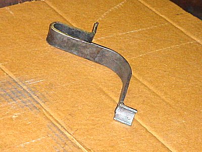
BP0280 Billy Hook, tripod
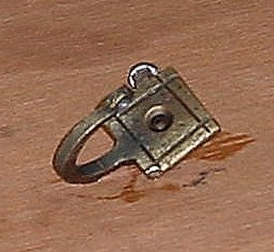
Adjustable Billy Hook - Putting Eyes to Good Use
by Strine
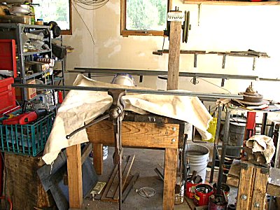
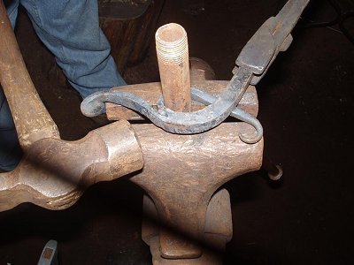
BP0006 “Campfire pot holder” got a recent airing and I thought this article might make an interesting blueprint as well. This shows the whole tripod but it's how the height of the pot is adjusted that I reckon makes this worth adding. The hook is the long bar with a handle bent at right angles. It can be positioned at any height, limited only by the height of the tripod and the length of the hook. The first one I sold was to a mechanical engineer…he'd never seen such a thing. And I suppose that's where the appeal is; not in that it can hold a pot over the fire.
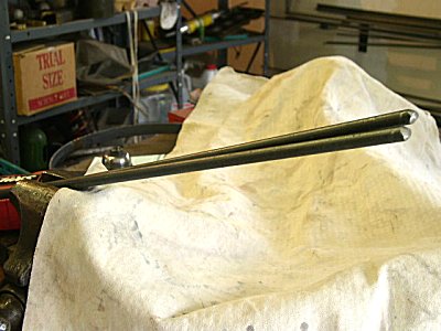
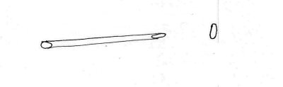
Shown is the business section of my infinitely adjustable campfire hook. It's even more infinite than the usual chain and hook arrangement.
As you may pick from the photo it consists of …
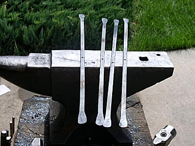
a) a part with an eye on each end and another part with an eye on the end and a double eye or a “wrap” a bit further back.
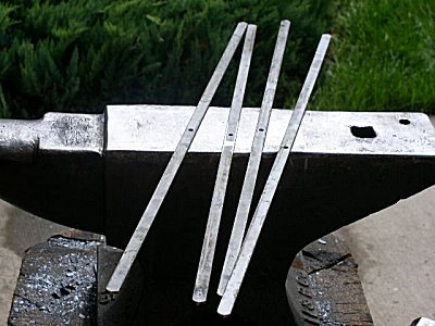
All the material is 3/8 round. About all I can say in relation to dimensions is that the triangle you can see is pretty much equilateral… all the sides are the same length. Yes OK, all the angles are the same as well.
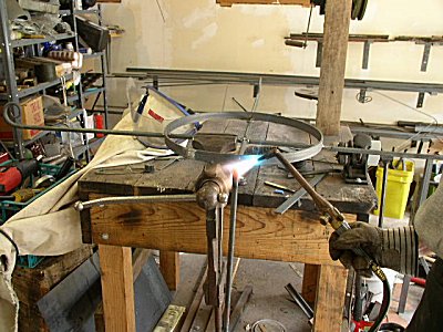
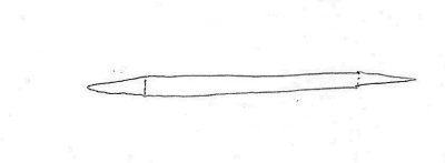
This is the view from the other side. The thing is based on an old locking principle the name of which escapes me. It is not just a matter of knocking out the eyes, putting it all together and hoping it will work; i.e. that the bottom eye will grab the shaft of the hook. The easiest thing I found to do was get it roughly right then tweak it in the vice when cold.
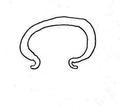
Here we see the hook all the way down. To get it there you lift up the bottom eye. If you're not careful it will just crash all the way to the handle.
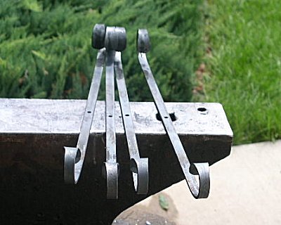
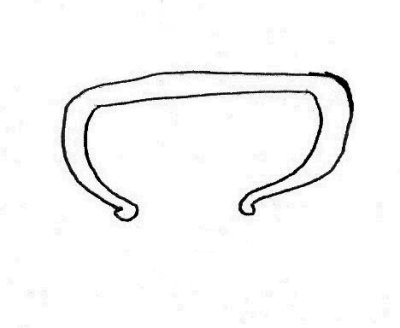
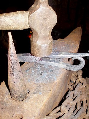
…and to lift it all the way up just haul up on the handle. That's the secret; it goes up easy but doesn't go down because any weight locks the hook between opposite sides of the bottom eye. This is where the tweaking in the vice comes in. It has to be just so to work.
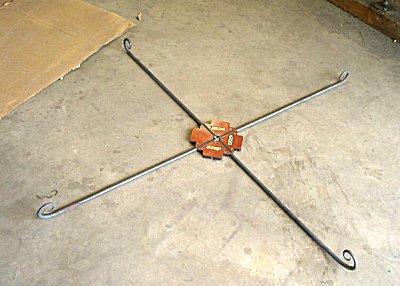
This is looking from above. Hopefully the orientation of all the eyes is a bit clearer.
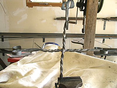
The hook hangs free in the adjusting gismo but the adjusting gismo has to hang from the head of the tripod.
Anyone for a billy of tea? That's an old dunny can (about 8 gallons or about 70 pounds) full to the brim. My Mechanical Engineer mate tells me the legs will collapse long before the hook lets go. The legs are actually starting to bow with this weight but it's hard to tell. All we need now is a blueprint on turning eyes.