

Steve Sells
-
Posts
9,156 -
Joined
-
Last visited
Content Type
Profiles
Forums
Articles
Gallery
Downloads
Events
Posts posted by Steve Sells
-
-
IForgeIron Blueprints
Copyright 2002 - 2011 IFORGEIRON, All rights reserved
BP0766 Building a Forge fire pot
by Swiftden
Hello Everyone my names Allan and I'm from South Australia.
What can i say this web site is an inspiration.
I will be borrowing (stealing) ideas from everyone elses home made forges for my design.
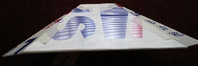
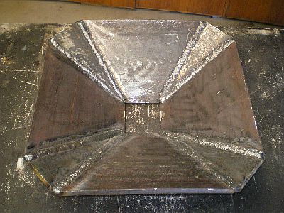
I decided it would be made out of 10mm(3/8") steel plate for the fire pot. I mocked up a template out of corflute.
http://iforgeiron.com/content/blueprints/700/766/01.jpg
http://iforgeiron.com/content/blueprints/700/766/02.jpg
http://iforgeiron.com/content/blueprints/700/766/03.jpg
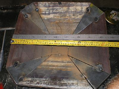
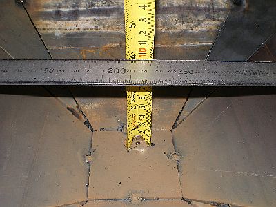
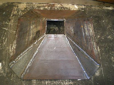
Pot is 100mm(4") deep and 430mm(17") across.
Well about 15 cutting wheels later on the 4" grinder and i had all my parts.
I have tacked them together ready to start seam welding them up tomorrow.
This is what i have so far :-
http://iforgeiron.com/content/blueprints/700/766/04.jpg
http://iforgeiron.com/content/blueprints/700/766/05.jpg
The square in the bottom will not be welded in it is just tacked there to assist construction.
I am not sure yet what i am doing for the blower hole i thought about putting in a clinker breaker but does that mean you dont then put in a grid? or do you have both ?
Well got the inside and outside seem welded today. bowed the wide sides a bit but nothing a few belts with the sledge wont fix i think
Also removed the square from the bottom
http://iforgeiron.com/content/blueprints/700/766/06.jpg
http://iforgeiron.com/content/blueprints/700/766/07.jpg
Gday mate . I can post actual dimensions of pieces if it helps? Im still nutting out the clinker breaker for it. your welcome to copy it if it helps i don't know how it will work yet .
It just worked out that way(design). It will have a lip welded all the way around yet.I made the sides first and attached them to a square and put a straight edge across the top of them and measured up from the base until i got 100mm (4") deep pot . seemed that was the best depth referred to by most. Then i just measured the gap between side to come up with the triangles. I could not work out how to do the side in one piece using the formula some have used but i thought the advantage was the my corners of my pot are not as sharp.
Making a cardboard template really helps to visualize the end result.
Got side tracked looking for steel today for the forge build. found this lump of steel and thought it might make a good temp anvil unless i find something better.
It weighs 139kg (305lbs) have been told it is cast steel not cast iron not sure if that makes a difference or not . I think it was a weight of sorts on the back of a heavy machine.
It is 28cm(11") tall, 83cm(32") across top, 70cm(27") at waist, the base half circle cut out is 15cm(6") across the bottom.
It has two holes in the top one at each end which i assume were for locating pins.
http://iforgeiron.com/content/blueprints/700/766/08.jpg
http://iforgeiron.com/content/blueprints/700/766/09.jpg -
IForgeIron Blueprints
Copyright 2002 - 2011 IFORGEIRON, All rights reserved
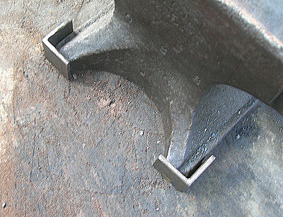
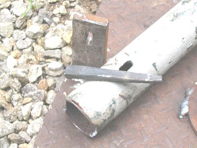
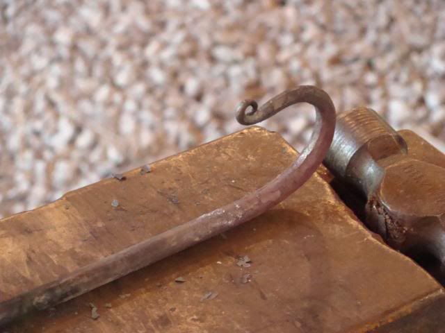
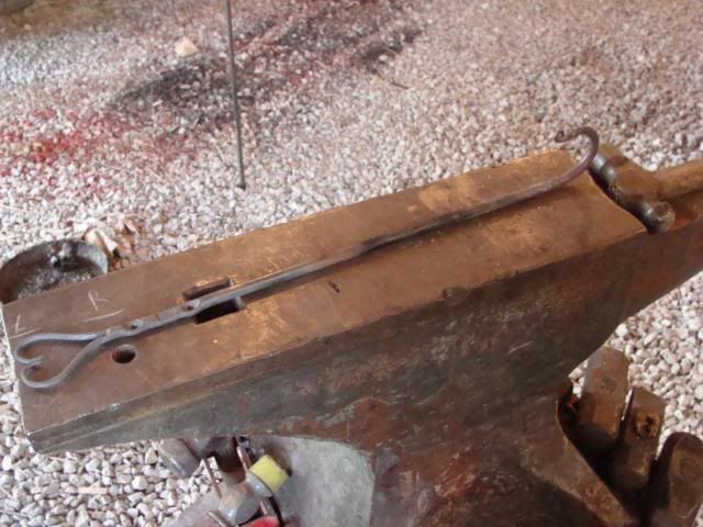
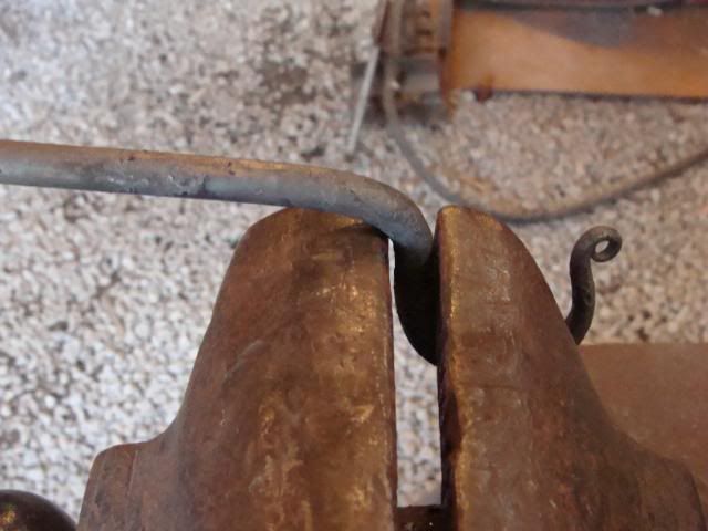
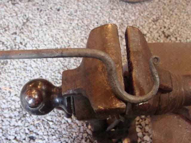
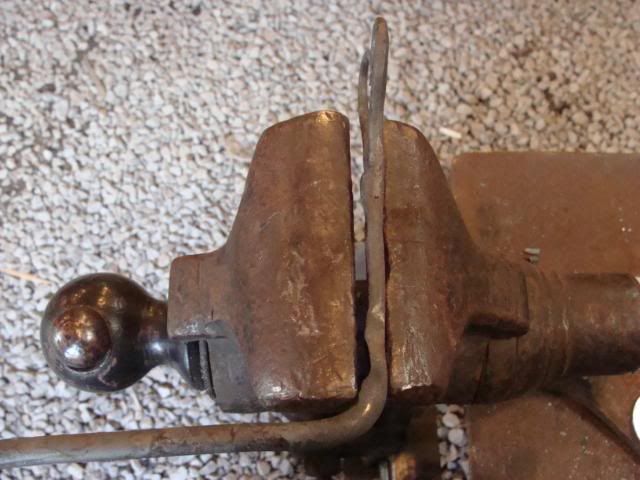
BP0767 Bending Fork
by Tubbe
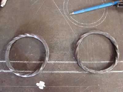
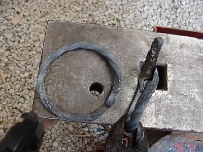
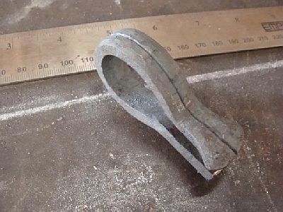
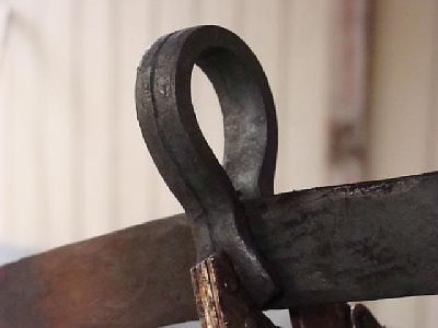
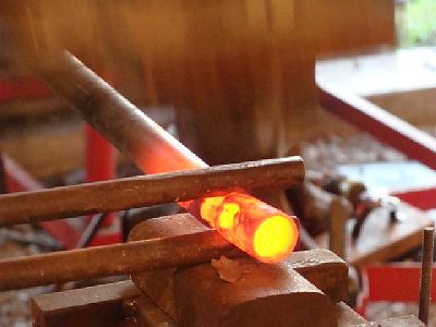
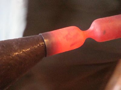
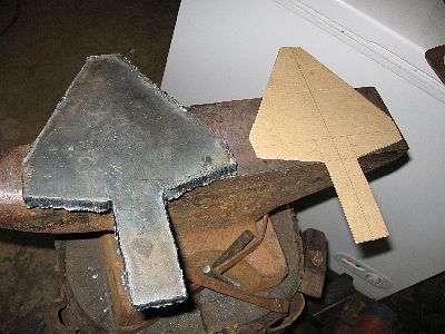
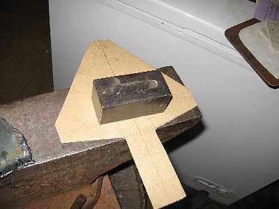
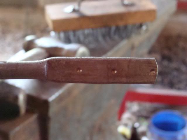
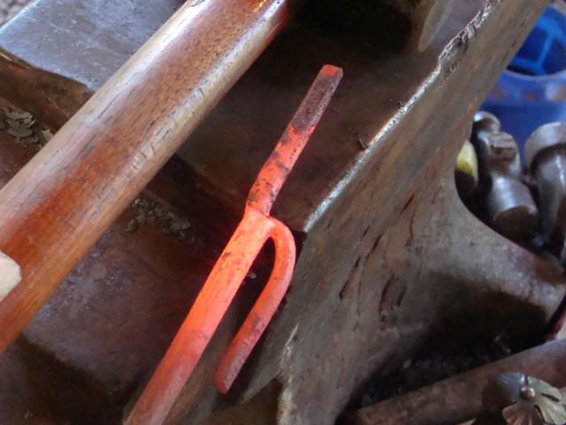
Started a little project a couple of weeks ago. I had a piece of round bar about 1,5" diameter, 4,5" long, laying around... I've looked at it many times, and finally one day, I threw it into the forge. I tapered down a shank (1") and popped it into my hardy hole and made the upsetting there. This is for a smaller anvil, and I noticed that the anvil actually heated up quite a bit, so be careful and cool the hardy hole bit of your anvil doing stuff like this. To fuller down the middle part I made myself a spring fuller from two pieces from a crowbar forged to shape and welded onto the "spring". Heat treated and all...
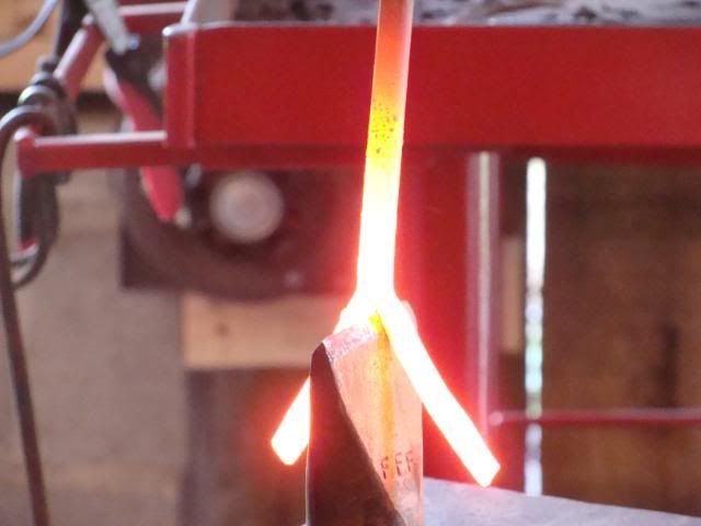
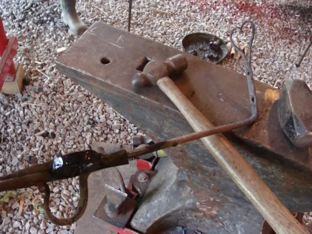
Now I have to draw the fork part out a bit further and split it in two. Wonder what diameter I should aim for? I am thinking 5/8"-ish. It's mild steel, perhaps even larger.
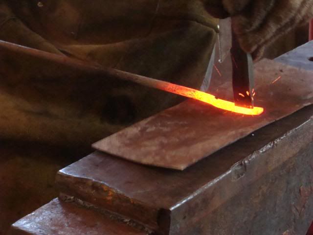
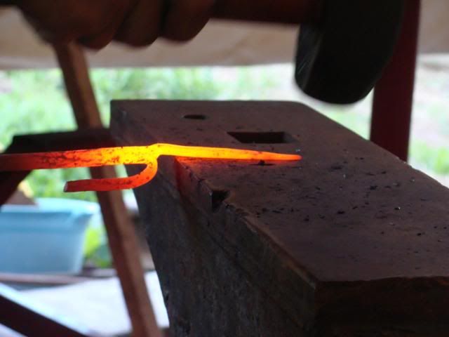
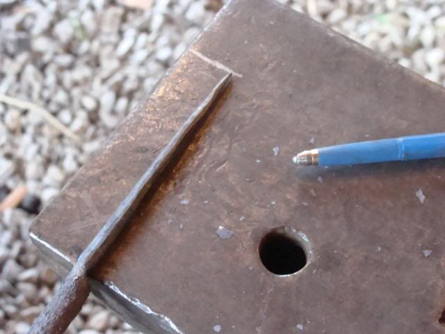
I'll try to hot cut the split. It's tempting to do that in the upright position in the hardy hole, but making a straight cut like that sounds impossible, or what do you think? Still, the plan is to do it horizontally from both sides...
This tool is made to fit my large anvil with a 1,5" hardy hole. That's why I used a stump of square tubing as a shank...
Quite hard work doing "heavy" stuff like this by hand and alone...
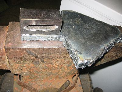
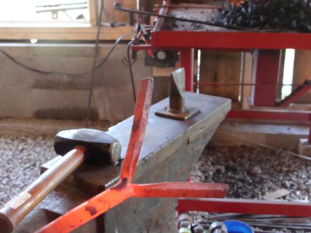
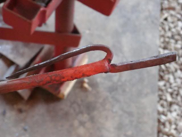
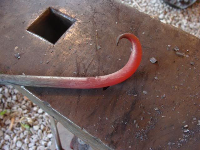
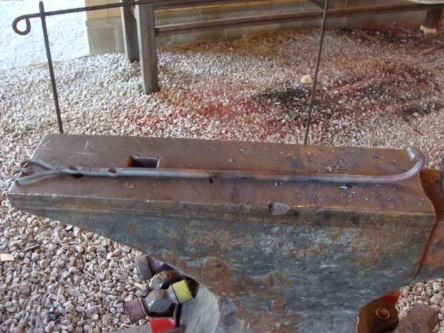
The bending fork is ready for use! I think it turned out very nice.
It actually wasn't mild steel... when I made it ready for center punching for the split line, i quenched it, and it hardened up quite a bit... my center punch went "popp". Had to regrind that one. Thought I did spark test it from the beginning, must have been blind. So, for the final stage i just normalized it. Hope that's ok.
It's a nice ring to it as well... probably could tune an instrument with it -
IForgeIron Blueprints
Copyright 2002 - 2011 IFORGEIRON, All rights reserved
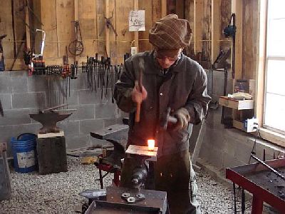
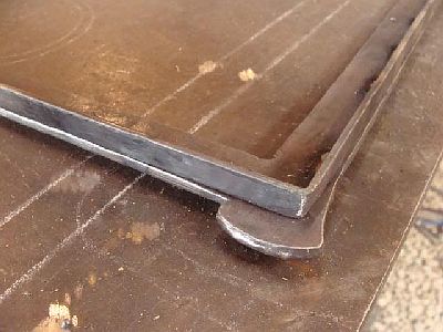
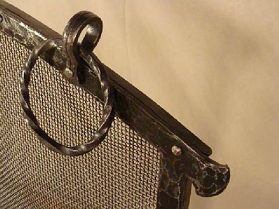
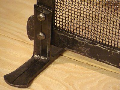
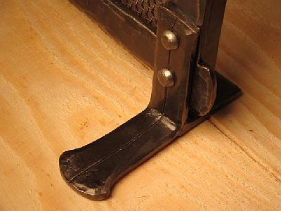
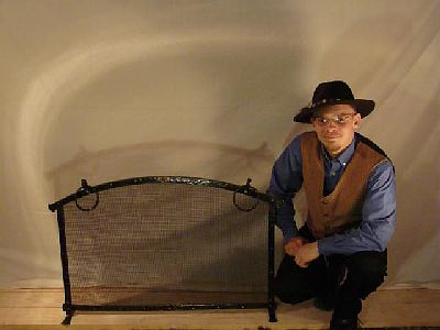
BP0763 Fireplace Screen
by Dave Custer
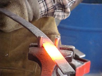
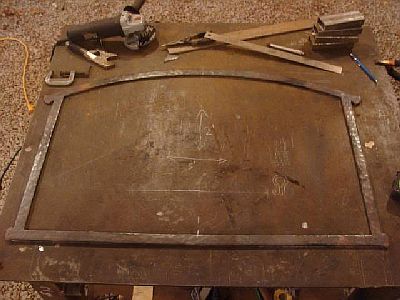
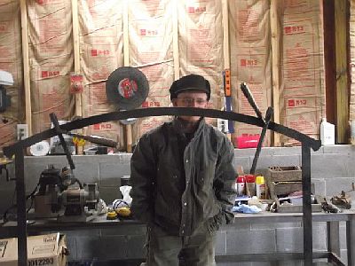
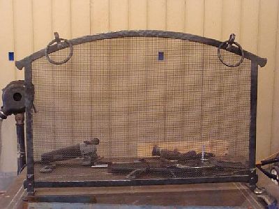
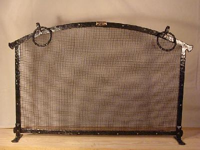
It has been well nigh a year since I made a fireplace screen. The last one I made was the big 3 foot x 4 foot screen for a client in Louisville, last May. I sold the sample screen that I carry around to craft fairs, so I need another one for this years season. I stick with a small standard size for craft fairs. The price has to be kept down and the size needs to be standard to increase the chance of selling it outright at a show. The screen I am working on now is 2 feet tall at the center, and three feet wide. Front-piece material is 1/4"x1" flat bar. It is hammer textured and the joints are mig welded. The welds were ground, heated and textured over. Here are the pictures that show yesterday's progress.
This is the design. Or does four sides drawn on a table count as a design? LOL The curve at the top took me some thinking to figure out. However, I finally cracked the method and got it drawn. Some of you may know what that straight line in the middle of the drawing was for!
I decided to let the top and lower bars extend past the side bars with flared upsets. I used an upset method I saw on Andrew Molinaro's promotional video.
Double hammers while the piece is clamped in the vice! MAN that works GOOD! And it's a ton of fun! LOL
I spent 5 hours and 40 minutes on the screen yesterday. This includes "design" time, forging and fabricating, making a vice-held bending fork, and doing a few test pieces.
At the end of the day!
So what do you think? How is my time compared to what I've gotten done? Am I working too slow or am I progressing at a decent rate? Be honest! If I'm slow, tell me. If no one tells me straight, I won't know where to improve.
Fire away!
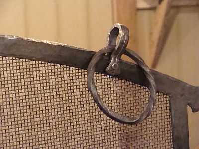
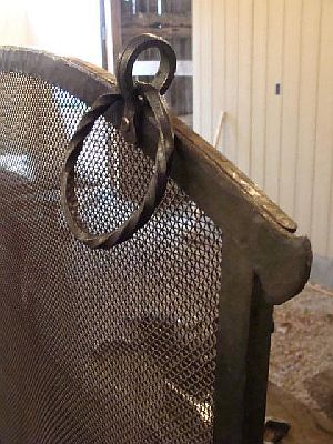
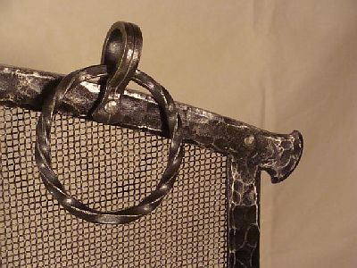
The handles for the screen are 5/16" square stock. They are circular with a reverse twists and are forge welded. They turned out nicely, but the first pair I tried I wasn't paying proper attention and twisted BOTH the SAME way! So, back to the band saw and start all over again. Upset, scarf, center mark, twist, reverse twist.....whole lot of wasted time. However, it happens (to some dumbos like me it happens more often,) and regardless of whether or not it was wasted time it still goes into the time figuring for the screen.
The handles are held on by two 1/4"x1/2" FB brackets. A matching flare is on the front side of these brackets and a simple chisel line runs down the center of the bracket.
The feet were the killer. I burned up two of six pieces I cut for the legs. Two others I spent a heap of time forging out and then finally decided I didn't like them.
Finally I decided on a matching upset flare like on the lower and upper firescreen pieces, with a center chisel line that matches the handle brackets.
Sorry no pictures of that yet. I'm going to get back on it tomorrow and hopefully finish it out. Now I just have to make the backing frame (1/2"x1/8" FB,) and assemble everything.
I spent another 5 hours and 30 minutes on it today bringing my total time up to 11 hours and 10 minutes. It looks like I'm going to have a 15-18 hour screen maybe.
More progress on the screen yesterday. Now I have to rivet the back frame to the front frame. I should get that done tomorrow and I'll then post completed pictures with total time, materials, and intended price for professional review!
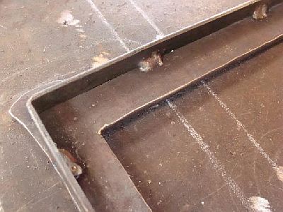
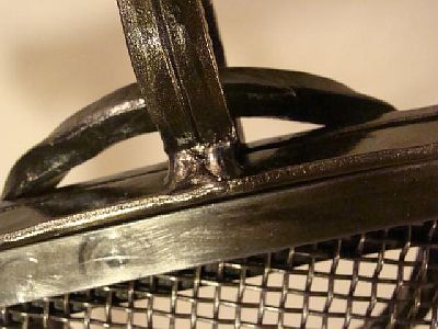
This is the rear view of the screen frame. I added a lip as you can see. I like this lip as it hides the edge of the screen and it VASTLY improves the overall finished look of the screen IN MY OPINION! I certainly do not hold that MY method is THE method. A lot of awesome screens have been produced with no lip and they blow anything I think about producing, out of the water.
This is my "cowhorn mustache" picture! hahahaha!
The handles!
The feet are attached but I still didn't get pictures of them.
I went with 1/8x1/2" for the lip around the frame edge and the backing piece. I should have went heavier and next time I'll go with the 3/16"x3/4" as suggested.
I've got a few visible welds which are the result of poor design and execution. However, they are on the back of the screen and are not in your face shouting "LOOK AT ME I'M MIG JOINT!" Little consolation I know!
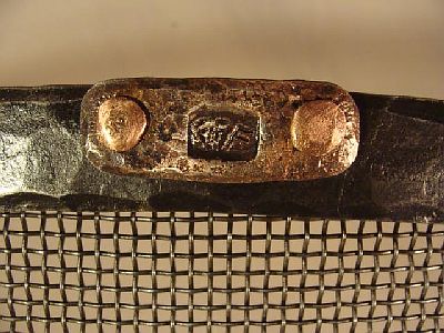
These are the visible welds! One behind the feet because I riveted the feet on BEFORE I riveted the back frame on, so I could not put a rivet down in the lower corners. One behind the handle brackets.

My edges have this lip on it that hids the sandwiched screen and gives an overal finished look!
And that's all folks!
Now this is the painful part. Timing and subsequent pricing!
This screen took me 20.5 hours to complete. That includes all mistakes, tool making for the screen, test pieces, design, reruns....everything.
I have $114 in materials. This includes grinding wheels, gas to pick up metal, coal, sandpaper,clear coat, raw steel, rivets.......everything that went into making the screen.
I figured that up and to make $30.00 an hour (low balling compared to the advice I've been given on here and elsewhere) this is a $720 screen. OUCH! What was that someone was talking about on here??? Oh yes perceived value! I may have to give that a try! LOL
Yes I know the price of chop and weld firescreens are. I wonder if potential customers do though! LOL I guess I'll find out this weekend. I'm going to a one day Italian street fair kown as the Knoxvill Opera. I've got to set up at 5 AM Saturday morning and demo from 10 AM till 10 PM. It's going to be a long day! It would make it worth it if someone bought the sreen! LOL Or ordered one. An order would be better because I have a show on the following weekend as well. It would be difficult to put together another screen in that time!
Thanks for all of the kind complements. I do realize that I am not anywhere near on par with professional blacksmiths yet, but I enjoy my work, strive to work hard, and hopefully will improve with time and practice. I' love to be able to get an apprenticeship for a few months maybe this summer or during the upcoming winter. I believe I would advance much faster.
I do like the personalization idea and it is one I will most likely adopt in the future. I think that would be a good selling point. Right now I do not have a letter stamp set which is unfortunate. However, as soon as I can get my trailer painted, I'll be caught up with expenses for a while and may be able to splurge a bit and buy some smaller tools. -
IForgeIron Blueprints
Copyright 2002 - 2011 IFORGEIRON, All rights reserved
BP0765 Bird Feeder Hook
by Dave Custer
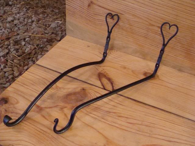
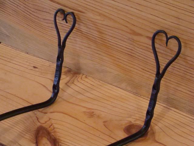
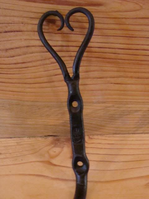
As offered and as requested, here is a step-by-step tutorial of my heart-themed bird feeder hook.
I should have mentioned this before, but these step-by-step instructions do not cover pieces I claim a copy right to. Anyone here is welcome to try to reproduce these piece. I encourage you to come up with your own variation and exercise your own imagination in your work, but if you are hard up for ideas, don't worry about copying what I'm doing! You are MOST welcome to try it.
I sell this piece as a bird feeder hook. The idea is, the extended hook gets a bird feeder, or hanging plant, or dinner bell, or WHATEVER, away from the post, beam, or board the hook is mounted on.
This tutorial will cover two variations of the bird feeder hook. One is a simple J-hook style and the general shape and forge work would be classified as a beginner level project. The second variation features a flared scroll type hook with a (supposedly) graceful curl down to the scroll. This might be classified as an intermediate level piece as it is much more difficult to get an even, "kink free" curve, than it is to make the simple "cut-n-dry" shape of the first variation.
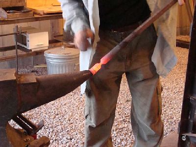
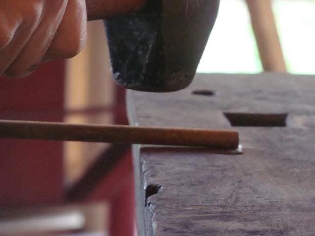
Step #1: Turn off the TV, hit the shop, and cut you a 20-inch piece of 3/8" round stock.
http://i302.photobucket.com/albums/nn114/fiddlegirl89_photos/Dave/DSC01711.jpg
Step #2: Mark a line with silver pencil or soapstone, 2-inches from the near edge of the anvil. Heat the end of the stock, place the end of the stock against the line, and step the metal to one side. You will use a half-on-half-off hammer blow to accomplish the step in your metal. Basically one side of the metal will "step" down and the other side will remain flat. In this entire process, keep the metal VERY hot the entire time. Just shy of welding heat is IDEAL. If you over-stress the metal from lack of heat, you WILL loose your heart. (The metal one that is!)
Illustration of a half-on-half-off blow. (cold)
http://i302.photobucket.com/albums/nn114/fiddlegirl89_photos/Dave/DSC01714.jpg
During the process!
http://i302.photobucket.com/albums/nn114/fiddlegirl89_photos/Dave/DSC01716.jpg
The result!
http://i302.photobucket.com/albums/nn114/fiddlegirl89_photos/Dave/DSC01719-1.jpg
http://i302.photobucket.com/albums/nn114/fiddlegirl89_photos/Dave/DSC01720.jpg
Step #3: Now center punch the stepped in side of the stock a couple of times. These will act as guide marks as you split the stock. Make sure they are in the center. I just eyeball it, but if you want, you can measure or use a center finder.
http://i302.photobucket.com/albums/nn114/fiddlegirl89_photos/Dave/DSC01721-1.jpg
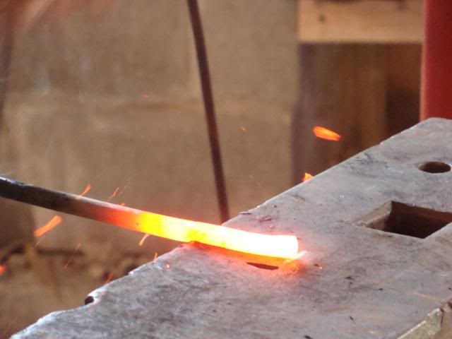
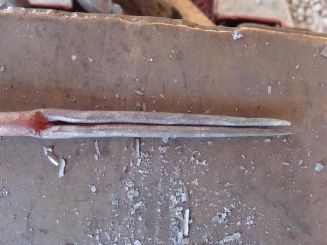
Step #4: Next heat the end of the stock and using your center punch marks, split the stock with a chisel. HEAT IS KEY! LOTS AND LOTS OF HEAT! The heat must be, not only on the end of the stock, but back in the shaft behind the step on the end. Chisel up to the end of the step. A cherry red heat is NOT ENOUGH! BRIGHT red is the lowest you can go and ideally you need to keep it in the yellow to bright yellow range! I HIGHLY recommend a cutting plate for this job. I use 16 gauge sheet metal to protect the anvil face. Some people use copper! You may be the best "chiseler" in the world, but you WILL miss eventually and your anvil face will remind you forever. Spend ten cents and buy a cutting plate!
http://i302.photobucket.com/albums/nn114/fiddlegirl89_photos/Dave/DSC01723.jpg
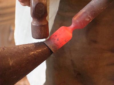
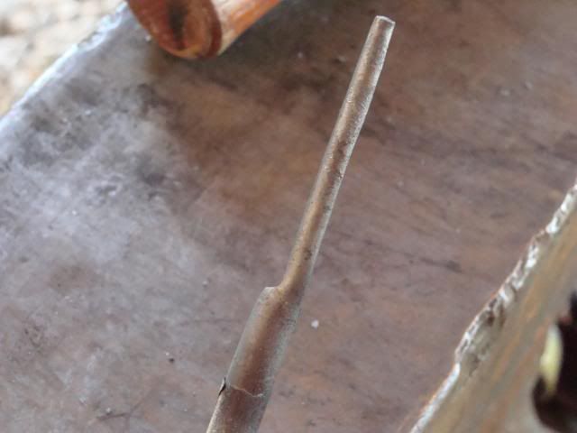
Step #5: After you have chiseled completely through, use your hardy to seat the cut and spread the two prongs apart! Once again, LOTS AND LOTS OF HEAT!
http://i302.photobucket.com/albums/nn114/fiddlegirl89_photos/Dave/DSC01725.jpg
(That picture shows you the IDEAL working heat and location of that heat for the entire "split heart" forging process!)
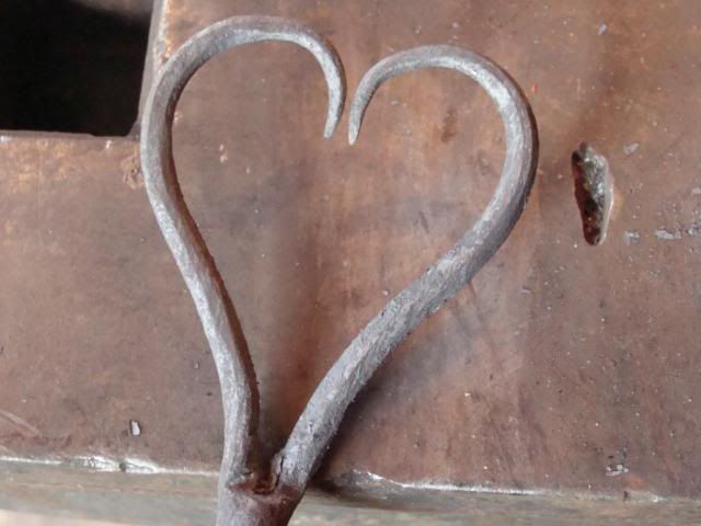
The result of this seating and spreading should look like this!
http://i302.photobucket.com/albums/nn114/fiddlegirl89_photos/Dave/DSC01726-2.jpg
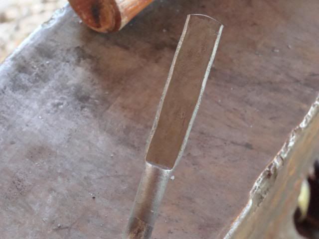
Step #6: Next, one prong should be straightened and one should be curled back as shown below! Make sure you don't let the stock twist when you curl the prong back. It will try to twist, but keep it straight and again.....HIGH HEAT! Also, you'll probably have one prong that is a little bigger than the other. Bend the larger of the two out of the way and leave the smaller one straight. This makes it just a bit easier to get the prongs the same length. (This curl is called a convenience bend.)
http://i302.photobucket.com/albums/nn114/fiddlegirl89_photos/Dave/DSC01727-2.jpg
Step #7: Taper the straight prong using your preferred tapering method! Then make a mark on the anvil that designates the length of this prong. This mark is VERY IMPORTANT in making an aesthetically pleasing heart.
http://i302.photobucket.com/albums/nn114/fiddlegirl89_photos/Dave/DSC01733.jpg
http://i302.photobucket.com/albums/nn114/fiddlegirl89_photos/Dave/DSC01735-1.jpg
Step #8: Now bend the tapered prong out of the way and straighten the other prong. Once again, watch for twisting and DON'T let it happen. Lots of HEAT! Then taper out the prong. Taper the prong to the length of the mark you made. That way, it will be near the length of the other prong. When you are done tapering, straighten the first prong and hammer the two together.
http://i302.photobucket.com/albums/nn114/fiddlegirl89_photos/Dave/DSC01736.jpg
http://i302.photobucket.com/albums/nn114/fiddlegirl89_photos/Dave/DSC01737-1.jpg
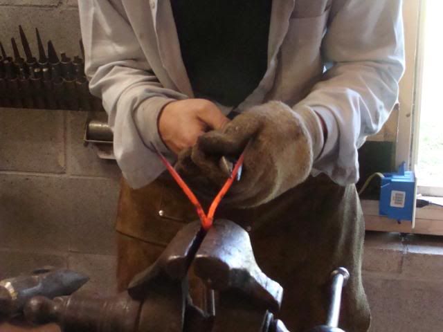
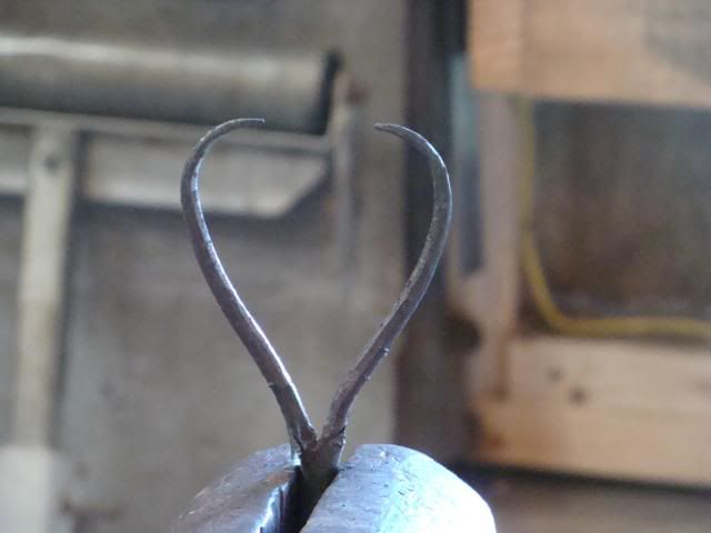
Step #9: Heat the two tapered prongs up, clamp the stock in the vice and use some needle nose tongs or pliers to begin shaping the heart. Use as many heats as you like, but try not to flex the base of the heart too much.
http://i302.photobucket.com/albums/nn114/fiddlegirl89_photos/Dave/DSC01738.jpg
http://i302.photobucket.com/albums/nn114/fiddlegirl89_photos/Dave/DSC01739-1.jpg
http://i302.photobucket.com/albums/nn114/fiddlegirl89_photos/Dave/DSC01740.jpg
Step #10: Now it's time to make the screw hole locations. I do two screw holes, and I space them far enough apart to allow my touchmark between the screw hole locations. I use a ball peen hammer to make my screw hole indentions, then I flatten a place between the two for my touchmark. I place my touchmark, straighten it all back out, and let it cool. AIR COOL!
http://i302.photobucket.com/albums/nn114/fiddlegirl89_photos/Dave/DSC01741.jpg
http://i302.photobucket.com/albums/nn114/fiddlegirl89_photos/Dave/DSC01743.jpg
http://i302.photobucket.com/albums/nn114/fiddlegirl89_photos/Dave/DSC01744.jpg
Step #11: After the metal is cooled, drill two 3/16-inch holes in your screw hole indentions. The advantage of the ball peen indention is that it eliminates the need for center punching or counter sinking your screw holes.
http://i302.photobucket.com/albums/nn114/fiddlegirl89_photos/Dave/DSC01756-1.jpg
This is where the variations come in. I'll do the simple version first and then the more complex one.
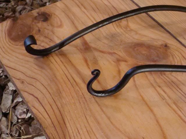
Step #12: Taper the end apposite the heart.
http://i302.photobucket.com/albums/nn114/fiddlegirl89_photos/Dave/DSC01757-2.jpg
Step #13: Put a finial scroll on the tip. The scroll should face downward when the heart is facing upward. Then bend a hook on the tapered end. The hook should face upward when the heart faces upward.
http://i302.photobucket.com/albums/nn114/fiddlegirl89_photos/Dave/DSC01762.jpg
http://i302.photobucket.com/albums/nn114/fiddlegirl89_photos/Dave/DSC01763.jpg
Step #14: Bend this hook downward, approximately 90 degrees using the
vise. (pictured cold)
http://i302.photobucket.com/albums/nn114/fiddlegirl89_photos/Dave/DSC01766.jpg
http://i302.photobucket.com/albums/nn114/fiddlegirl89_photos/Dave/DSC01767.jpg
Step #15: Now heat and bend the bar approximately 90 degrees, just below the last screw hole. This is done in the vise with the screw holes clamped in the vise. (again shewn cold)
http://i302.photobucket.com/albums/nn114/fiddlegirl89_photos/Dave/DSC01768.jpg
Step #16: Wire brush a apply bee's wax while hot.
http://i302.photobucket.com/albums/nn114/fiddlegirl89_photos/Dave/DSC01773.jpg
Now for the more difficult variation! Ignore steps 12-16 and pick up at step 11.
Step #12: Flare the end of the bar apposite the heart. For a wide flare use the cross peen hammer. For a medium flare us the edge of the hammer face. For a small flare, simply flatten the end of the bar. Scroll the flare so that the scroll faces upward when the heart faces upward.
http://i302.photobucket.com/albums/nn114/fiddlegirl89_photos/Dave/DSC01759-1.jpg
http://i302.photobucket.com/albums/nn114/fiddlegirl89_photos/Dave/DSC01760-1.jpg
Step #13: Bend the hook at approximately 90 degrees, just below the last screw hole. Clamp the screw holes in the vise to bend as shewn.
http://i302.photobucket.com/albums/nn114/fiddlegirl89_photos/Dave/DSC01768.jpg
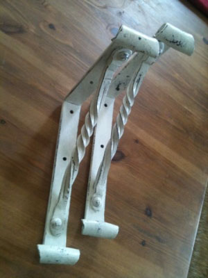
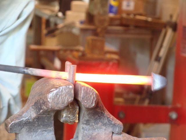
Step #14: Use a vise held bending fork to bend the bar, between the screw holes and the flared end, to a nice even curve. This takes practice so don't fret if your first isn't all that great. Work out any kinks and make sure the
curve is even.
http://i302.photobucket.com/albums/nn114/fiddlegirl89_photos/Dave/DSC01765.jpg
http://i302.photobucket.com/albums/nn114/fiddlegirl89_photos/Dave/DSC01761.jpg
http://i302.photobucket.com/albums/nn114/fiddlegirl89_photos/Dave/DSC01783.jpg
Step #15: Wire brush and apply bee's wax while hot.
The end results!
http://i302.photobucket.com/albums/nn114/fiddlegirl89_photos/Dave/DSC01792.jpg
http://i302.photobucket.com/albums/nn114/fiddlegirl89_photos/Dave/DSC01793.jpg
http://i302.photobucket.com/albums/nn114/fiddlegirl89_photos/Dave/DSC01794.jpg
http://i302.photobucket.com/albums/nn114/fiddlegirl89_photos/Dave/DSC01795.jpg
And that's all folks! I welcome questions and comments. If something didn't make sense just let me know and I'll try to explain it better and/or get more pictures!
Thanks! -
IForgeIron Blueprints
Copyright 2002 - 2011 IFORGEIRON, All rights reserved
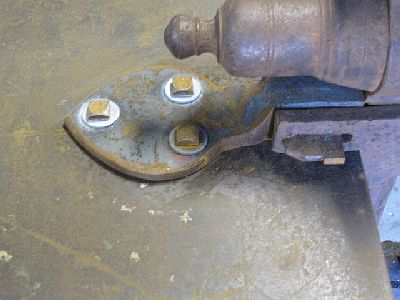
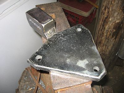
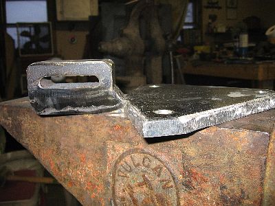
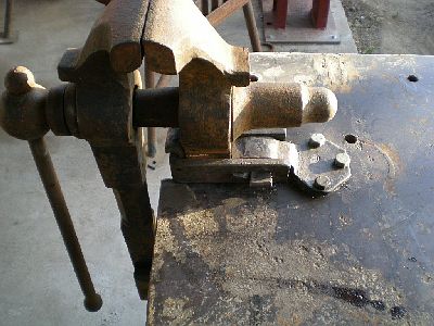
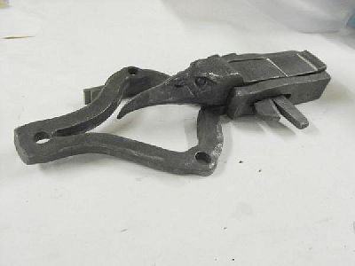
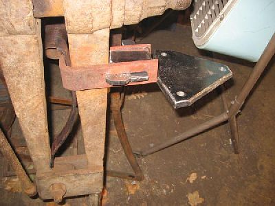
BP0761 Anvil Hold Down
by irnsrgn aka Jr. Strasil and Glenn Conner
Your anvil is dancing all over the stump.
Cut 4 short pieces of angle iron.
Drive a piece of angle iron into the stump at each foot in order to hold the anvil.
The anvil is easy to remove from the stump, just pick it up.
-
IForgeIron.com Blueprints
Copyright © 2002 - 2011 IFORGEIRON.COM, All rights reserved.
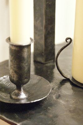
BP0768 Candle Cup
by FireyFurnace
Posted 23 June 2011 - 10:06 PM
Ok so what?.....this makes the fourth candle cup I've made, so now I'm qualified to teach! Sure!
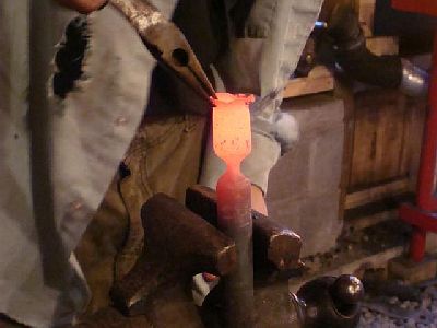
Step number one! Select your material.
Step #1: Get some pipe or tube or whatever in the the world it's called. The stuff I'm using is about 7/8-inch INSIDE DIAMETER material and rather thin wall.
Step #2: Stuff a rag or a wad of paper in the end you are holding. This will keep cool air in the pipe and not allow the hot flames and gasses to move up the pipe, heating the end you are holding.
Step #3: Heat the end of the pipe and fuller it. If you want your candle cups to be identical, then get a metal ruler, put masking tape at the length you want your candle cup to be, and then hold this ruler near the metal while you are starting your fuller. Fuller BEHIND the measurement, not on the measurement that you want your cup to be. (A fuller is a scisor tool that makes a thin spot in metal. I used mine under the treadle hammer.)
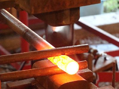
(Pipe needs to be fullered at a bright red and can be worked down to a black heat. Rotate as you tap the fuller and use LIGHT blows or you will smash, not fuller the pipe. White heat is TOO HOT!)
The result of the fuller looks like this, looking down the pipe! I used a 5/8-inch fuller!
Step #4: Now thin the edge of the candle cup using the horn tip. Keep the stock in line or level with the horn.
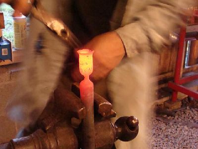
Step #5: To begin the candle cup flare, angle the pipe upward as pictured below!
Your hammer should be impacting the steel as pictured below
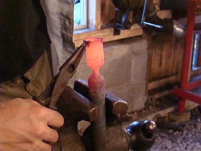
Step #6: To make a rolled-top candle cup, hammer as picture below using a glancing blow that hits the metal and comes back towards your chest. (I would not recommend using an untucked unbuttoned shirt as you see me in.) Continue to guide the metal around until the thin tip has bend rolled around and tucked under forming a nice "bead" around the candle cup lip.
Step #7: If you want a plain flared candle cup lip, skip step #6 and just dress the edges created in step number five.
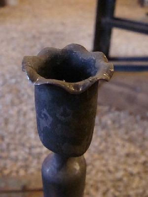
Step #8: To creat a rippled top candle cup, skip step #6 and #7 and do the following.
After flaring the candle cup top, use scrolling tongs or tweezers to ripple the candle cup top. Grab the lip with the tongs and rotate downward. (Pictured below.) Move 180 degrees to the other side of the candle cup and do the same. Now rotate 90 degrees (or half way between the two ripples aleady formed,) and repeat. Move 180 degrees from the last ripple and do it again. You can leave it at that, or ripple between the four other ones. The key to keeping it uniform though is to move across the candle cup. Don't just start in one spot and go around.
And if you are fast like me......
Just kidding! Speed has nothing to do with it......
You will achieve this.......
Cut this off from the parent material in the mid point of the fuller. Drill the hole to size and tap or rivit onto your candle stand.
DO NOT QUENCH PIPE!
You should rarely quench metal, but never ever ever quench pipe or you might get a nice concentrated steam cannon in your face!
Hope this helps! Now go make some candle cups!
CurlyGeorge
One suggestion to flare the end. Take the socket end of a tire iron and cut it off. weld the open end down to a hardy shaft or angle iron (for the vice), and it works a little better than the end of the horn. I use this method on all of my pipe candle holders and it works great for me. Give it a try. Nice looking candle cup, though. -
Posted 09 March 2010 - 12:41 AM
IForgeIron.com Blueprints
Copyright © 2002 - 2011 IFORGEIRON.COM, All rights reserved.
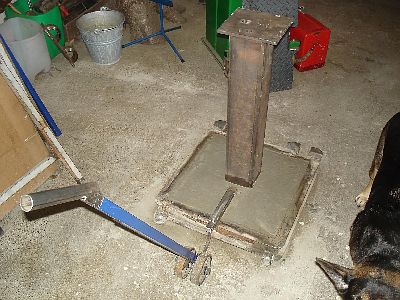
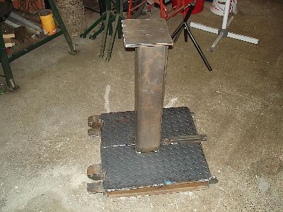
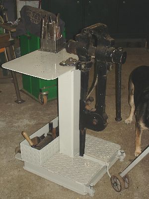
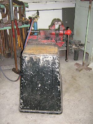
BP0769 Vise Stand
by LDW
Here's a vice stand that LDW made. The vice was Lyle's grandfather's. We put it at a good striking height, 29-inches. We had to make this horse head out of 2.25-inch round stock, and would not have been able to make it without the support that this setup gave us. It's pretty sweet
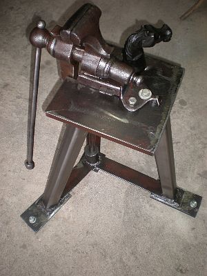
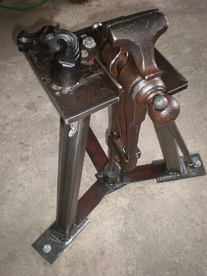
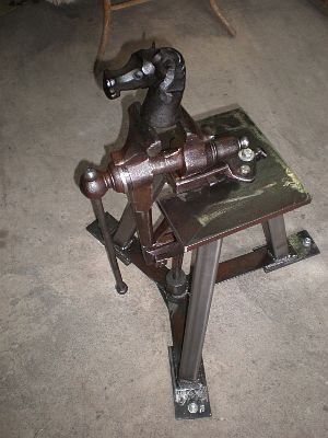
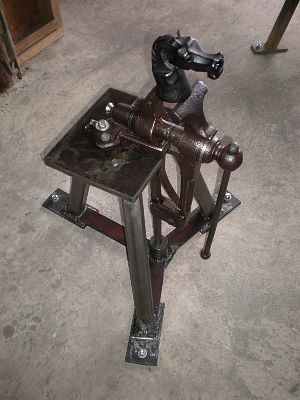
It's the best vice setup I've ever worked on, and I've worked on many different setups.
The right side was left for upsetting on and working on hammer handles and such, but the left side is cut away for longer bars to pass.
29-inches to the top of the jaws.
Rubén
Is the stand similar to the one you mentioned in another thread, that you and your brother made for Tom Clark?
Brian
It is similar, but this one has some improvements. The vice has been moved closer to the center of the equalateral triangle of the base. This was Lyle's idea, and it gives alot more support and backing. That is why we had to cut one side of the plate away so you can pass longer stock through like Southshoresmith noted, but it allowed for us to leave the right side with the table backing for upsetting and other things like installing wedges for hammers. I have since made racks and hooks for holding tools, but I have not taken any pictures yet. Lyle and I are going to Louisiana tomorrow to do a class and a conference, but I'll take somemore pictures when I have more time. This is the best vice setup I've worked on so far.
A post vice can be like an anvil, but it must be mounted securely, like an anvil. This stand is set up at a good striking height, and it can be anchored down very easily to concrete or the ground. I have worked on some good shop vices that had posts buried into the ground a good distance but none at striking height, and this one is portable. It is also mounted closer to the center of the equalateral base, and it does have the right side of the mounting plate for upsetting and installing hammer handles. All these things make it better than any vice and stand that I have ever worked on. -
IForgeIron.com Blueprints
Copyright © 2002 - 2011 IFORGEIRON.COM, All rights reserved.
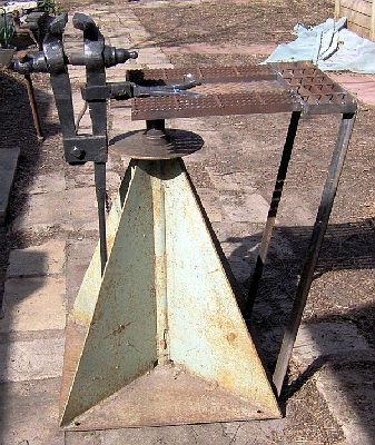
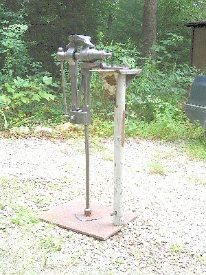
BP0770 Vise Stand
by Pascalou
Posted 11 January 2009 - 05:34 AM
Hello
Here a vice stand.is an alternative of the system of displacement of the anvil stand of " markb". weight: approximately 130 kg
A+ P.L
-
IForgeIron.com Blueprints
Copyright © 2002 - 2011 IFORGEIRON.COM, All rights reserved.
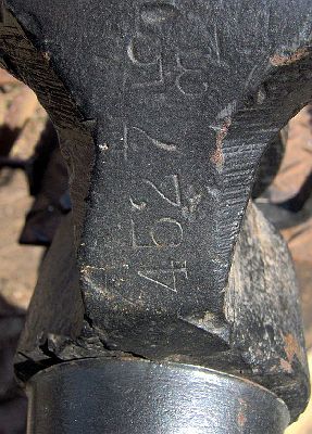
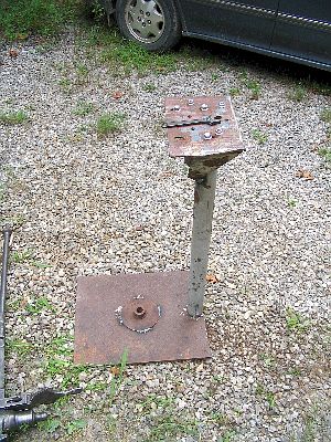
BP0771 Vise Stand
by Iron Falcon 72
Posted 22 February 2009 - 09:01 PM
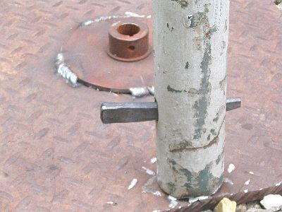
Here's a new post vise stand I just finished by modifying the green base. This is a small vise, 3.5". I have a larger one that needs a new spring and wedges. It will be next.
The stand was originally set up with a chain saw sharpener on top. Got it and the sharpener for $50. The sharpener's table is shown with the post still attached where I cut it off. I had no idea the post was solid but my Milwaukee "The Torch" cut-off blade went right through it.
The new top is all scrap from the junkyard. I hadn't done any welding in about a year so it started a little rough. I plan to store tongs and hammers on the sides and end.
The only markings on the vise are the numbers shown. The "35" may refer to it's size. I know it's not much to go on but, does anyone recognize the brand?
I'm sure that there are better arrangements for the tongs and hammers but, I have only a small area to work in (6x8) and no room for another rack. And at this point I don't have so many of either.
I'm not sure how much it weighs. The flat bottom actually makes it less stable. It rocks on every little bump on the floor. When I decide where it will finally reside I will bolt it to the floor.
-
IForgeIron.com Blueprints
Copyright © 2002 - 2011 IFORGEIRON.COM, All rights reserved.
BP0772 Vise Stand
by Frosty
Posted 08 April 2009 - 09:45 PM
How handy the vise stand thread comes up now. I just finished a folding vise stand I started before my last surgery took me out of action for a while.
I added a couple chachkas to hold hardy tools, hammers and my twisting wrench. There's a 3/4"+ lip around the plate behind the vise so I can lay tools on it and keep them handy.
It has one coat of paint, will get another and a little gold trim to match the vise, my shop colors are green and gold.
Frosty -
Posted 22 July 2011 - 09:27 PM
IForgeIron.com Blueprints
Copyright © 2002 - 2011 IFORGEIRON.COM, All rights reserved.
BP0773 Vise Stand
by Andrew OC
Posted 01 March 2010 - 07:16 AM
Hi y'all,
here is a vice my TAFE college has used for an age. The origins of the cast iron trapizoid are lost in the mists of time. It is quite heavy, just movable with a long bar.enjoy
AndrewOC -
Posted 22 July 2011 - 10:27 PM
IForgeIron.com Blueprints
Copyright © 2002 - 2011 IFORGEIRON.COM, All rights reserved.
BP0774 Traveling Vise Stand
by Vance
Posted 24 August 2010 - 04:28 PM
Since I don't have a "show" trailer, and some shows/festivals won't allow vehicles/trailers in the vendor's area, I needed a portable vise.
3 major parts, (the wedge, nuts, and bolts don't count), assembles and breaks down with only a small Crescent wrench and small hammer.
Base is 1/2" thick plate from the scrapyard, upright is the shaft from an old warehouse fan, (the base of which is well on it's way to becoming my portable 24" dia. forge.
The vise leg is slightly longer than the upright from the base allowing the two forward bolts to "tension" the unit by trying to pull the mounting column "up" while pushing the "leg" down. It'd disassemble easy enough, but getting it back together would still require at least loosening the two forward bolts.
Since most of the "stability" comes from you standing on the base plate it's stable enough for making twists and bends in smaller stock or holding pieces for grinding. I won't be twisting and 1" stock at shows anyway, so this will suit my purpose.
If in your moving around you wind up with a concrete pad to work on you can always drill holes in the corners and install Hilti or Red Head anchors in the concrete. 1/2' lead shield anchors and lags would also probably be good enough, and when you move on there will only be 4 small holes as any sign you were ever there.
-
Posted 22 July 2011 - 10:46 PM
IForgeIron.com Blueprints
Copyright © 2002 - 2011 IFORGEIRON.COM, All rights reserved.
BP0775 Vise Stand
by Curly George
Posted 14 December 2010 - 10:50 PM
I had a customer come to me and ask if I could locate a mounting bracket for his 6-inch leg vice, and make a spring, too. The vice used to be his grandfather's and he could't locate the bracket or the spring. I checked Ebay, Craigslist, and asked around our area. But nobody knew where to find a bracket. I have a 6-inch vice that I use in my shop, but the one that he has is a bit beefier than mine. So, I got some 1/2-inch plate, and had a local man that has an O/A torch cut out a bracket that I made a template for. I made it a little bigger than mine. I also had some 1 1/2-inch square bar. So I cut it, drilled a series of holes down the center (for the wedges) and cleaned the inside with a file. It came out a lot better than I expected. Now I have to clean up the not so great cut around the outside of the plate and weld the wedge block on. Here's a couple of pics of what I have so far. I'll post the finished pics in a couple of days.
Southshoresmith
Having done it my self its actually not that hard of a part to forge. Not much harder than forging a hammer.
Curlygeorge
I got the bracket cleaned up and welded together. Tripple pass welds all the way around. Beveled down each side, first. I think that the guy will be happy with it. I am!
Clinton
Yes it is doable, but I would advise the help of a striker. I did mine myself by hand. The slit and drift was quite a work out, but I was able to use the powerhammer to flatten the end. Not as nice as southshoresmith's but I can say that I forged it
Grant Sarver
Thought you might like this.
Curlygeorge
Got everything done, including making up the new spring. Everything is tight, when I drove in the wedge. He's supposed to come and pick it up in the next day or two.
-
Posted 22 July 2011 - 10:14 PM
Posted Today, 08:33 PM
IForgeIron.com Blueprints
Copyright © 2002 - 2011 IFORGEIRON.COM, All rights reserved.
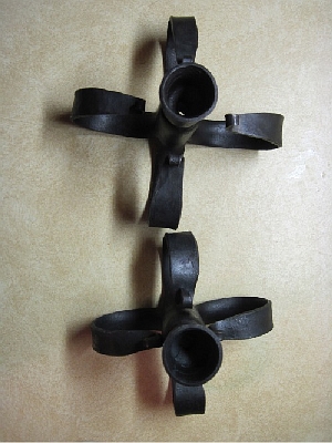
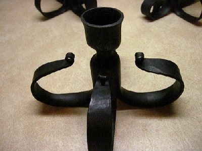
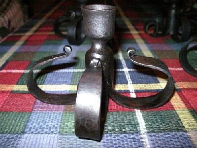
BP0776 Unitity Candle
by Primtechsmith
This is a Unity candle I made for my kid sister's wedding this past June. The cross is 1" square and the four parts are attached with angle iron pieces with rivets. A 1/4" round bar is tied in a knot placed in the middle(for her tying the knot...haha). It is about 15'' tall. base is about 8"x11" I think. Everything is riveted, tenoned, or screwed together(the candle cups). They were happy with the outcome and so was I.
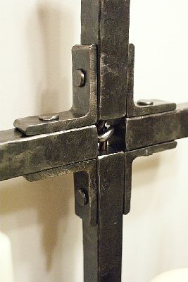
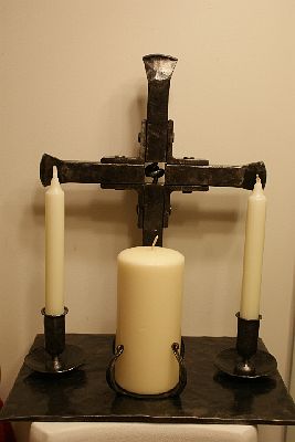
I had a lot of help with making it all come together from "yesteryearforge". I am lucky to have a good hand to siphon my hallucinations into finished items. And to remind me that no matter the project it is all a bunch of small steps.
Hoping to get into the forge soon to practice some more...
Peyton -
Posted 26 July 2011 - 08:49 PM
IForgeIron.com Blueprints
Copyright © 2002 - 2011 IFORGEIRON.COM, All rights reserved.
BP0777 Combo Vise Stand
by Southshoresmith
I took this photo months ago and meant to post a then.
We made this first as a vise stand only to then decide that we needed a place for the Hossfeld bender as well. It has worked out very well in the shop and gets used frequently. I thought I would share it with all of you. It is the result of several people's input and labor. This is used in the center of the shop for heavy bending, for holding jigs, and also times when you just need a big strong vise. The vise is a 7-inch Fisher double screw chain vise. It opens over 12-inches and grips like a bull dog. I once griped a 2-inch round bar 3-feet long...it held my weight out on the end (210 lbs) off the floor and did not move. -
Posted 27 July 2011 - 11:59 AM
IForgeIron.com Blueprints
Copyright © 2002 - 2011 IFORGEIRON.COM, All rights reserved.
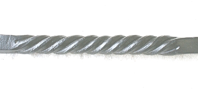
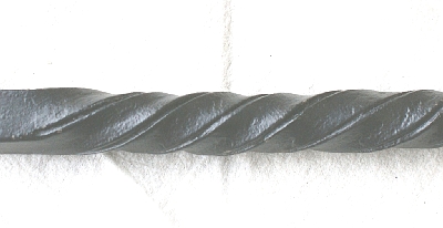
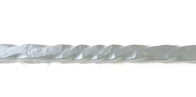
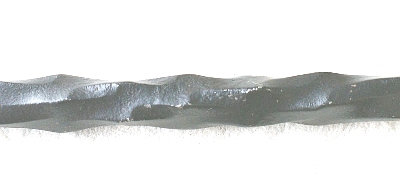
BP0778 Twists in Bars
by John B
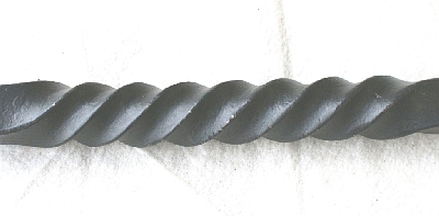
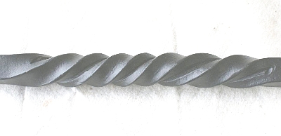
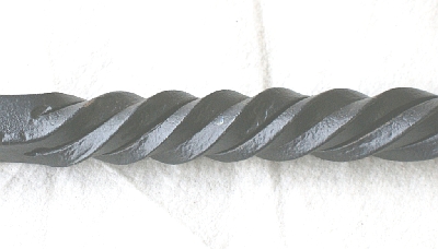
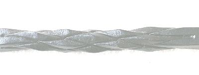
TWISTS IN BARS
NOTE: Twists can be right handed or left handed.
Right hand twists are illustrated. Pictures are large for ease of understanding method and appearance.
Tools used when producing these,
Forge, Anvil, Leg vise, Hammer, Centre punch, Hot set (Hot chisel/incising tool,) Appropriate tongs, Twisting wrenches, Water dipper, Water tank/supply, Wood block, rawhide or wood mallet, a Wire brush, and a sacrificial plate for cutting through on the cage twist in solid bar to prevent damaging anvil face.
HOW TWISTS DEVELOP
12mm square bars used in sample pictures
From Basic Twist to Cage Twist
Done Cold, produces an even twist but it has a limited length of pitch before it shears. In practice, it is limited by ability to apply pressure on wrench and grip on other end.
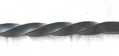
Done Hot, twists can be tighter (shorter pitch.)
Two sides incised on the centre line and twist, Appears like Two flat bars twisted together
Four sides incised on the centre line and twist, Appears like Four square bars twisted together
Four sides incised on the centre line with a pair of opposite corners knocked off into a rounded edge and twist,
Appears like Two round bars and two square bars twisted together
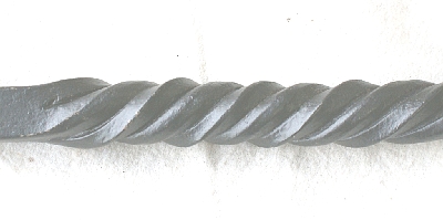
Four sides incised on the centre line, all the corners knocked off to form a rounded edge and twist, Appears like aRope twist
Four sides incised on the centre lines, then split right through, (this could be from all four sides or just two)
The bar is then twisted a known number of times, and then untwisted half the number of turns whilst pressure is exerted to push the split part of the bar back into itself, compressing the twist and forcing the cage outwards to the required shape, adjust if required. Cage twist pictured is a parallel sample.
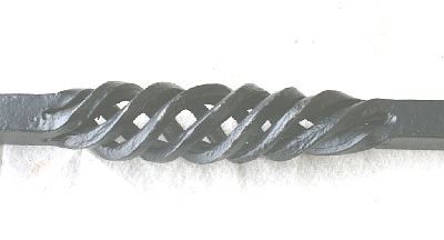
These twists are all made using the same basic twist and using different numbers of incised lines on the centre lines, if you move the position of the incised lines before twisting, and forging the corners, you will get even more different effects or appearances. The combinations are only limited by your imagination.
Here is another sample that is similar but different to a previous one shown. This one has four sides incised, not on the centre line this time, but near and adjacent to two of the edges, with the two opposite corners knocked off into a rounded edge.
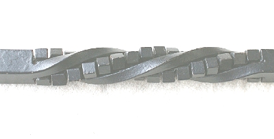
Another variation is a small flat is forged the length of the twist on each corner/edge, an incised line is applied on each edge and then the bar is heated and twisted. Ribbon twist
Or these, sometimes called Water twists
Incise two opposite sides near to the edge, the length of the twist section required, and then make a short ¼ twist, then make a reverse ¼ twist at the desired spacing, and repeat along the required length
Or increase the twist rate to ½ turn and reverse ½ turn
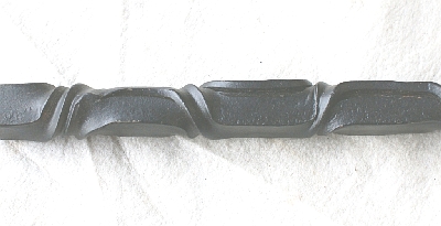
Same but different for comparison...½ twist gives a chunkier appearance
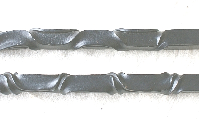
Or you could do these twists in the same direction (no pics available)
If you apply the same principle about development, you can produce a pineapple twist, or three separate styles of twists starting with;
A square bar is twisted, then the twist’s high spots are forged back to the original square bars’ size.
The bar was differentially twisted as opposed to equal twists, and you can clearly see the difference it makes in the appearance of the facets. This was due to lack of uniform heating throughout the twisting operation.
If you then reheat the bar and reverse the twists, you get a Knobbly effect
However, if you incise the four sides on their centre line, twist a known number of times, then flatten to square, incise again on these ‘new’ sides and reverse twist half the number of previous twists, and if arranged correctly will give aPineapple twist or Diamond Twist effect.
This from iforge source Cube twist
Incise down centre line on all four sides, then cut using a hacksaw or thin blade on angle grinder the equal sections diagonally across opposite edges.
-
Posted 28 July 2011 - 07:54 PM
IForgeIron.com Blueprints
Copyright © 2002 - 2011 IFORGEIRON.COM, All rights reserved.
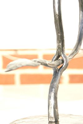
BP0779 Metal passing through metal
by Primtechsmith
After seeing a few pass-thru examples in print and in person, I decided to play around with it and incorporate it into an idea I have been kicking around. It is 1/2-inch round with a 3/4-inch slit and drifted hole. The leaf was made after passing the nub through the hole. It is tenoned on the end to go into the round plate disc I beat up and slightly domed.
I wanted the hole to look somewhat like a hollow in a tree...It still needs to be refined, but is a start.
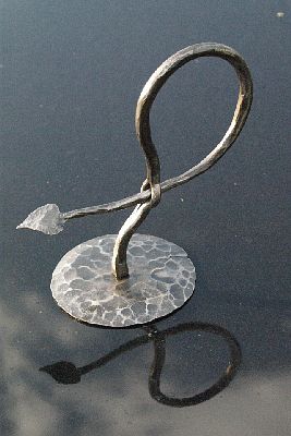
The best thing about it is the base for me. I lightly hit it with a 4 1/2-inch grinder to highlight the high spots. With a coat of clear spray paint it turned out okay.
Not sure what to do with this "element"...but, I do like the idea and lines of it. Maybe in the future something functional can come of it...This one ended up in Iron in the Hat.
Ideas and criticisms are always welcome...
Peyton -
Posted 08 August 2011 - 12:55 AM
IForgeIron.com Blueprints
Copyright © 2002 - 2011 IFORGEIRON.COM, All rights reserved.
BP0780 Twists
by Sask Mark
So I was in my shop today looking at the nails on the rafters (you know, the place where you hang everything?), and said to myself, 'Dang, I have tooooo many zip discs! Now what am I going to do about it?' So I made these....things. -
Posted 08 August 2011 - 01:05 AM
IForgeIron.com Blueprints Copyright © 2002 - 2011 IFORGEIRON.COM, All rights reserved.
BP0781 Candle Holder
by Mark Snagel
A while back "Curlygeorge" posted pictures and instructions on how to make candle holders out of pipe. I left a comment saying how much I liked the holder and would copy it some day. George sent me a message the other day and said that he was looking back over his posts and saw my comment. He sent me the pictures via email, along with the steps of how to make them, (BP). Easy to follow and great pictures. Not many people these days will go out of their way without prompting as he did. This is the sign of a great teacher. Through his willingness to share and teach I made four of them today. Hopefully someday I can step out and help a budding blacksmith as he did.
Here they are: I made 4 of them.
They are all mostly identical with small differences that make each unique. The last one I made has one of the legs shortened into a carrying handle (first picture). I thought this would make that one........ Oh well, actually I was multitasking and burnt the end slam off one leg. Hence the handle. Thanks for looking, keep sharing knowledge.
Thanks George! Mark -
Posted 04 September 2011 - 01:34 AM
IForgeIron.com Blueprints
Copyright © 2002 - 2011 IFORGEIRON.COM, All rights reserved.
BP0782 Freon Tank Extended Forge
by Fluidsteel
Posted 10 August 2011 - 11:27 PM
I'm building a freon tank forge. For now it will be a venturi burner, but will be modifiable to be blown.. This is getting me by untill I have the time to do a dual burner PID controlled temperature adjustable heat-treat/forge. I didn't like that they weren't QUITE deep enough for a big 15-18" chopper blade. I'm also going to add angle iron to the back and make a firebrick back door for bigger/longer stock.
I started with my shop's scrap bin... Lookie here free(on) tanks!
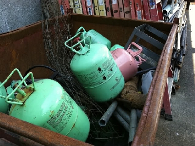
I picked out a couple....Applied the safety goggles and respirator....cut one in half with the angle grinder, and cut off the end of the other.....
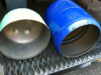
Then I stuck them together... Actually, I stuck them together BEFORE I cut the end off of the blue tank, it took me ten minutes to get them apart. I think that means they fit together nicely.
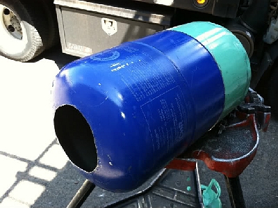
Next, allowing for 2" of inswool and around 2" of 3200 degree refractory cement I centered my burner hole and drilled it with a hole saw...I put in a 1.5-inch BI nipple. It is in there now with locknuts from an EMT conduit connector, but it will be welded when done.
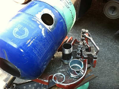
I made this burner... it's based on a Zoeller Z burner. I bought the parallel fitting, but the rest was scrap including the 1" SS 304 pipe. I'm going to forge a flare into the end of the SS....
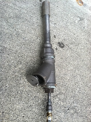
Put it on the pipe rack and with the help of a hammer to keep it from kinking bent it to bring the burner in on a tangent.... Like a 6 on it's side...
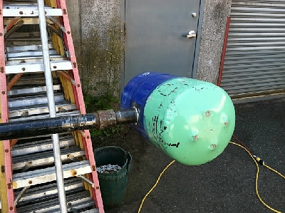
Next, I'm welding a couple 1-inch pipes to the side. Going to run a couple pieces of 1/2-inch rod through them with a 1/4-inch plate between for a tool/tong rest. I ordered and added a PID controller with a thermocouple shield, and a couple other items to get my temps set for normalizing and heat treating..
I'm a beginning bladesmith, and want to do blacksmithing as well..
I'm also adding angle iron to the front to allow a firebrick door that slides open, left and right like a big aircraft hanger...I will weld it up this weekend. If the PID comes, I'll add the thermocouple too!
What do you guys think? I'm a total newbie and am coming at this from HOURS of reading and researching... This is my version of slapping something together because I want to forge NOW!
Brian
Thomas Powers
Tight at room temp and tight at hot temp are not the same; but a few self drilling self tapping metal screws through the overlap will make sure it won't work loose even when hot.
Phil Krankowski
You probably also want a pass thru out the backside, and having a slot for extra wide things is very nice too.
Matt Bower
Good work. 2-inches of castable is way too much, IMO. It'll take a very long time to get up to temperature and waste a lot of fuel, assuming you aren't planning to run this thing 16 hours a day. 1-inch is more than enough, and less would do fine.
On further reflection, forget my last question. Regardless of how you're planning to set and hold the temperatures for heat treating, that forge isn't going to do it for you. I'm sorry to say it, because I know you've done a lot of hard work on this thing so far, but it's just not the thing for what you want to do. It'll be good for forging big stuff -- it'll work for forging blades as well, although it's excessively long for that. But the burner coming in the side like that is always going to create a hot spot, and because of that the temperature inside is going to vary a fair bit from one spot to another. The temperature your thermocouple reads will depend on where it's placed in the forge. For long, thin stuff like blades, you'll have serious problems obtaining even temps across the whole blade. It's the nature of the design. For heat treating, especially blades, you want as even a temperature as posslble throughout the entire interior of the furnace, and you want that temperature to be very close to the temperature you're trying to achieve in the steel. What you want is something like this:
http://www.dfoggkniv...S/DrumForge.htm
See how the burner comes in from the end and points down the long axis of the forge? No direct flame impingement on the side, or the blade itself, and the large interior volume lets the temperature even out. No hot spots.
Fluidsteel
A couple questions Matt,
One, it's not obvious from the picture, as I didn't show an after picture, but the burner inlet was bent on the tank to cause it to come in on an angle like a "b" on it's side. I was told that will help the flame roll through the forge. Do yo think that will help keep the temps even?
I was going with the thicker refractory because my research said that it will help keep the temps more stable, More mass does take longer to heat, but it also retains it's heat longer. Thoughts?
I could easily scrap this plan if it's a waste of my time.
For now, all I'm forging is 1084. No soak time at temperature is needed. 1475 and into the Parks 50. Normalizing also needs no time at temperature. So it seems that I should be able to hit my temperatures w/o too much trouble?
My other option, and what I planned on doing, is to scrap the tank as is, do another with two burner ports. And make a high low solenoid/PID controlled dual burner blown forge...
It would have a Low burner that when running would get the temps to say 1400 degrees max. The high burner controlled by the PID would boost the temperature to whatever I set. The PID's fuzzy logic figures out how long the burner needs to stay on, and I will "learn" to correct for overshoots.
Option B. Make a blown forge w/PID so I can read the thermocouple, and use it for forging. Then buy an Evenheat to do my heat treat. I want to do some stock removal kitchen knives with some PG O-1 and that needs the 5-6 minute soak times.
I need a smaller, somewhat portable forge now. I don't have the space for a drum forge. Besides, that drum forge would have 3 times the mass to heat than my freon tank, wouldn't it? Even if they only added a skim coat of refractory to keep the ceramic blanket from being damaged?
Matt Bower
Let me just say that I do my heat treating in a solid fuel forge because I also don't have the room for a drum forge, and I have not been satisfied with the propane forges that I've tried for blades. Even using a pipe muffle in a propane forge, I have never been able to achieve the sort of gentle, even heat that I want for heat treating. But I have not tried one exactly like what you're planning, so perhaps I shouldn't have been so forceful in saying it won't give the results you want. I don'tthink it will, but that's just speculation on my part. Not entirely uninformed speculation, but speculation nevertheless. With that said . . .
Even with the burner coming in on a tangent to create a swirl, you're going to have direct flame impingement on the interior that's going to create a hot spot. So while the rest of the forge is heating by conduction/convection, you'll have an area there that will be putting off a lot of radiant heat, and the closer you get to that spot the hotter it'll be. The hot spot may be bigger than with a burner that's oriented toward the center axis of the forge, and you won't get direct flame impingement on the blade, both of which are good things. But it'll still be a hot spot, and I think it'll still cause you problems. However, as I said, that's just informed speculation. I could be wrong.
I have given some thought to how to reproduce the effect of a drum forge in a smaller package, but all my ideas are untested theory so I'm a little reluctant to throw them out. I will offer one suggestion that you might try, if your design doesn't work out as hoped. I have tried a muffle in a propane forge with poor success -- the muffle just developed a hot spot where the hot spot in the forge was -- but the muffle was fairly thin. A thicker muffle might do better, especially with your design. I have considered a ceramic muffle of some sort, but the prices of mullite and similar tubes are pretty intimidating just for experimentation. You might be able to do it with castable refractory.
The drum forges usually don't have any castable in them. Just some ridigizer to lock own the fiber particles. (I suspect the rigidizer is just sodium silicate or something similar.)
I'll try to get to your other questions later.
Dodge
Rolling the burner flame helps IMHO, but there's still a hot spot. Two smaller burners can produce more BTUs than one large burner and be able to spread out your heat. There will be two hotspots but if they are aimed correctly, the overall result is more even heat. Still maybe not critical enough for exotic alloys but for overall forging you'd be happier. I'd also cut a back door. That's just me, but being able to heat the middle of long material comes in handy at times.
Edit: I was still typing when Matt posted, but what he said. As for mufflers or baffles, I believe this is how many glass furnaces work; a short wall between the burner(s), often ribbon type in design, and the main business area of the furnace.
Matt Bower
OK, a few other thoughts.
First, drum forges are mainly for heat treating swords. I think the design is scalable to a certain extent for smaller blades; if you're planning on doing 10-inch Bowies or kitchen knives you wouldn't need a 55-gallon drum. You might be able to apply the same principle to a smaller burner in a 5-gallon steel bucket lined with an inch of ceramic wool.
As for the thicker refractory stabilizing the temperatures, I guess that's true, although something the size of a blade doesn't really suck out all that much heat. But it'd also make the temperatures slower to adjust. (It occurs to me that with a really massive forge you might actually be able to run it up to temperature, cut the burner off, and use the residual heat in the forge to heat-treat with. However, I've never tried it, or had a forge that massive to experiment with!)
I'm not quite sure I follow what you mean about hitting your temps with 1084. Yes, it's fairly easy to heat treat well, but hot spots will still cause problems.
1084 will benefit from a short soak at austenitizing temperatures (1-2 minutes. at the temperatures you're talking about). If you really want a near-zero soak you'll want to go a bit hotter, more like 1525 degrees Fahrenheit. 1084 will still make a good blade with what you're planning. Frankly, there's always a certain amount of soak time built into the process, because you're bound to spend a little time eyeballing the blade and deciding whether it is fully up to critical. Roman Landes (German metallurgist) has a post about soak times for 1084 over on hypefreeblades.com. Roman is one of a few people I pay very careful attention to when it comes to the metallurgy of heat treating.
If you really want the best of both worlds, I think your option B is it. Forges aren't ideal for heat treating, and heat treating furnaces aren't ideal for forging. If you leave heat treating out of the equation, it becomes much simpler to design a good propane forge. A thermocouple on the forge seems like an overkill to me, but it won't hurt anything.
It is possible to build your own electric heat treating furnace, BTW, and it should be quite a bit cheaper than the commercial HIT furnaces I've seen, which are all quite expensive by my standards. Plus, DIY would let you choose the dimensions to suit what you want to do. All the commercial furnaces I've seen seem more or less oversized for blades, even most of the Paragon ones designated as being for knifemakers. (Although having a little extra capacity for heat-treating tooling and the like, isn't necessarily a bad thing.)
Fluidsteel
Long term I would plan on building a salt pot, and getting an oven as well. For now, I'm stuck with a forge. I'm going by the shop today. I might pick up a solenoid and put together a couple new tanks and make a blown forge instead. I honestly don't have much time or money in the venturi burner or the tank itself. More time doing the WIP post actually....
Maybe buy a box of crayons too.... and make a ribbon forge burner...
I'm ADD... Can't stay on, look at that anvil, topic long... It's easy to change direction for me if it's not the best choice for what I want to do.
Thanks for the link on the heat treat. I greatly respect Kevin Cashen.... I soak up all the info I can on heat treating..!
This is a short reply.. I'll think about all this and decide which way to go.
Matt Bower
I'm pretty interested in ribbbon burners, too, but according to folks here who've built and/or used them, they don't tune down well. So that's not really what you want for heat-treating, if that's still your plan.
Phil Krankowski
I'm pretty interested in ribbbon burners, too, but according to folks here who've built and/or used them, they don't tune down well. So that's not really what you want for heat-treating, if that's still your plan.
BTW, my forge is 150 cu inches. It gets melting hot and sips propane. -
Posted 04 September 2011 - 01:44 AM
IForgeIron.com Blueprints
Copyright © 2002 - 2011 IFORGEIRON.COM, All rights reserved.
BP0783 Shelf Brackets
by Dex
Posted 28 July 2011 - 08:14 AM
I needed a quick project to find an excuse to try some cut twists. I'm learning, so most everything I do is actually trying a technique or method out for the first time. I'm looking forward to a time when I will be repeating techniques!
These brackets are sized to support a 6-inch wide shelf. The red primer and ivory topcoat is scrubbed back and then waxed for a distressed look, it's not that I've painted on top of WD-40 ....
Frosty
Not bad at all! For an early project, it's actually quite good.
A couple of things: if you break the corners on the stock before you twist it will have a less factory look to the edges. If you break the corners heavily say till the breaks are almost the same width as the halves of the faces, then twist till the cuts are closed you'll have a "cable or rope" twist.
Transitions between twisted sections and flats or spreads for bolting, is MUCH easier if you carry the twist just into the transition area, then forge it back to square or into your connection.
Painting over WD-40 is how I do distressed, if my usual finish isn't distressed enough.
Frosty the Lucky. -
Posted 04 September 2011 - 09:40 AM
IForgeIron.com Blueprints
Copyright © 2002 - 2011 IFORGEIRON.COM, All rights reserved.
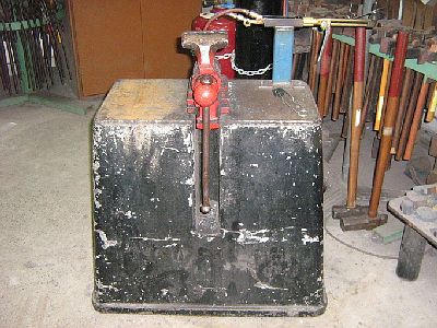
BP0784 Vise Stand
by FTK
Posted 13 March 2009 - 01:04 PM
I had problems with finding a thick steel plate as a base, so i made this thing.
So what do you think?
HWooldridge
That's the exact setup I have for my demo rig. 55 gallons of water in a steel barrel with an average sized vise will give you around 500 lbs of weight and it's easy to drain when the demo is over. I made a bracket on the outside of the drum to hold the vise leg, which makes the whole arrangement quite solid.
Keykeeper
Did it have a full leg or had it been cut short?
With a full leg, I would have made the mount the same, but put a piece of pipe just slightly larger than the leg in as a shroud from the concrete, with a piece of plate welded to the end of that (before the concrete is poured, welded to the pipe, for a solid bearing surface for the vise, as the mount would be plenty solid, and the leg would still be bearing the brunt of the hammer blows downward). If that makes sense.
Then, if the vise was needed on a bench sometime, just fab up another mount for that. Then you would have two mounting options in the shop.
Otherwise, looks very solid and stable.
FTK
The vice has a full leg, The bottom sits tightly in a piece of pipe that is welded to the main beam (stand). There are also some smaller beams welded to the main one for extra strength in the concrete.
Keykeeper
Oh, Ok, wasn't clear in the pics, looks like the leg was mounted right in the concrete. -
Posted 04 September 2011 - 10:02 AM
IForgeIron.com Blueprints
Copyright © 2002 - 2011 IFORGEIRON.COM, All rights reserved.
BP0785 Vise Stand
by nc-cooter
Posted 07 July 2009 - 04:32 PM
Finally got my post vise stand built. I used 1/2 inch plate and 2 inch square tube. The vise is only a 4 inch, but it's in great shape.
Thanks for looking.
-
IForgeIron Blueprints
Copyright © 2002 - 2006 IFORGEIRON.COM, All rights reserved.
BP0786 Wind Chimes
by Richard Thibeau
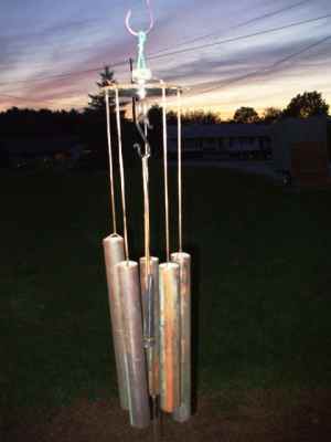
There is a mathematical process to determine the exact note you can get from each section of pipe. For those interested enough to bear the pain of complex math formulas, just Google "Wind Chime Notes" and find the reference you want to follow. For these wind chimes, I used a ratio relative to the size pipe.
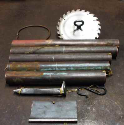
The parts needed to make the chimes were all laying around in the shop.......an old circular saw blade............1 1/2 inch diameter copper pipe.....rr spike for the striker......s hook......rectangle piece of steel
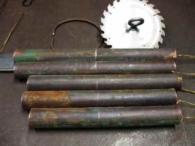
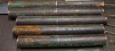
The pipe was cut into 5 pieces: 15 15/16 inch long, 15 in, 13 5/8 in, 12 7/8 in and 12 in. At one end, a hole was drilled 3/8 in from the end to thread the string for hanging. I used artificial sinew which is waxed for outdoor use.
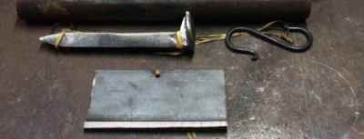
I used a rr spike for the striker to be hanging in the center. A piece of hard wood could be used as well, it strikes the pipes to make the tones sound. The rectangle piece hangs off the spike and is below all the pipes to catch the wind and move the striker.
To get the best tones, the striker hits the pipes at different points. The pipes are hung so that the striker hits each one at the marked line. For the 15 15/16 in pipe the line is 8 inches from the top, for the 15 in and 13 5/8 in it is 7 1/2 in, for the 12 7/8 in and 12 in it is 6 1/2 in from the top of the pipe.
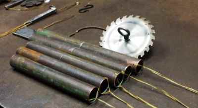
Once each pipe is cut, drilled, marked, and string added; it is time for assembly.
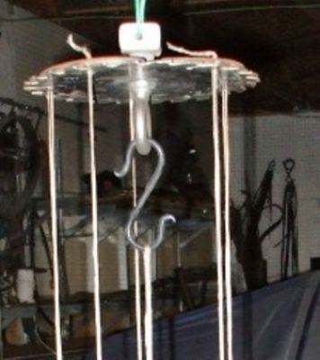
For the top part from which all is attached, I used a 7 inch circular saw blade with 5 holes drilled equally spaced for the pipes. The arbor hole in the center was filled with an eye bolt for the striker and wind catcher to hang from and secured with a nut and spacer that also serves as the upper attachment point to hang the whole works from.
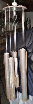
You need to hang each pipe so that the line previously marked for best tone will be at the same level as the striker with the wind catcher below everything.
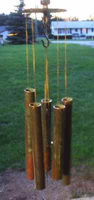
Once assembled, find a nice spot that catches the wind and hang them up. If everything came out right, they make a nice chorus in the wind and next to the house is a good spot.
BP0759 Forge Build
in BP 700 Series
Posted
IForgeIron Blueprints
Copyright 2002 - 2011 IFORGEIRON, All rights reserved
BP0759 Forge Build
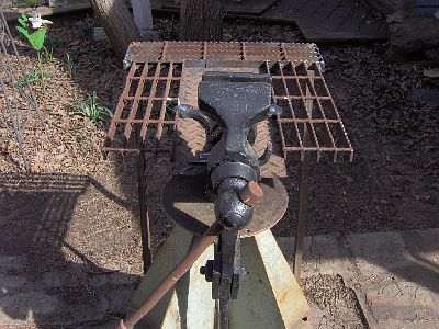
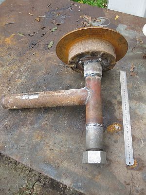
by caotropheus
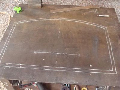
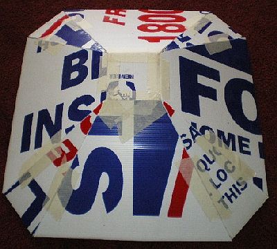
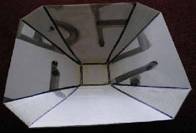
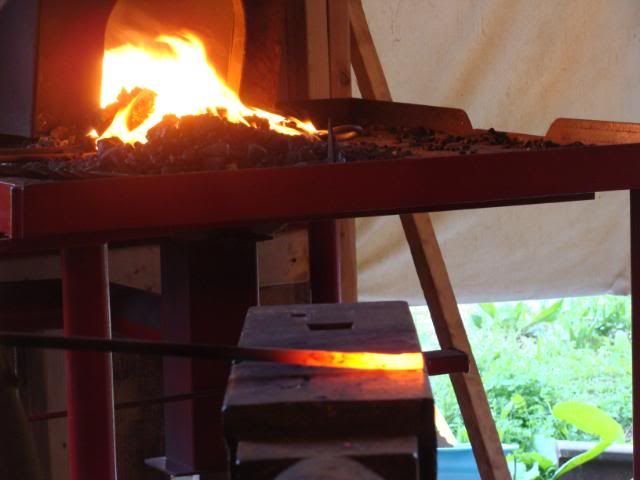
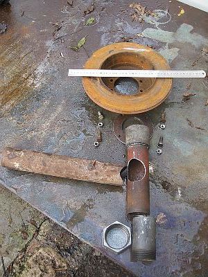
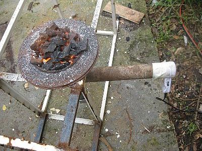
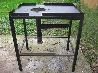
Build out of scrap material I had laying around, just bought the brake rotor at the scrap yard ($2) and the 4mm mild steel plate for the table.
The ruler is 40 cm long and sorry for the lousy welding.
By the way, this was the "light sabre" I used to cut the metal...
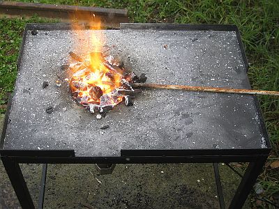
This was the first fire I lit for the picture. The pile of fuel I use is higher and always generously covers the piece I am heating. The forge works really well and the rod shown is a piece of round stock 12 mm, was red cherry in about half a minute. Now I am building small "gates" to close unused gaps I left in the frame surrounding the table top.
The table top is 70 cm long x 50 cm wide