

Steve Sells
-
Posts
9,156 -
Joined
-
Last visited
Content Type
Profiles
Forums
Articles
Gallery
Downloads
Events
Posts posted by Steve Sells
-
-
IForgeIron.com Blueprints
Copyright © 2002 - 2012 IFORGEIRON.COM, All rights reserved.
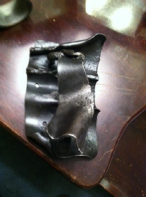
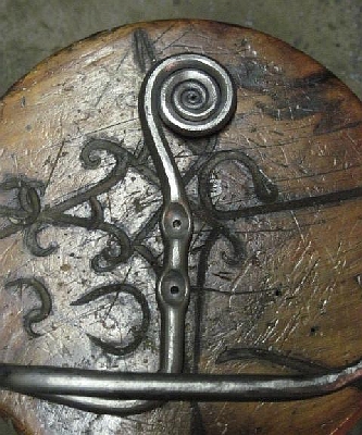
BP0812 Fold Forming
by Freeman
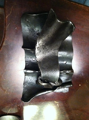
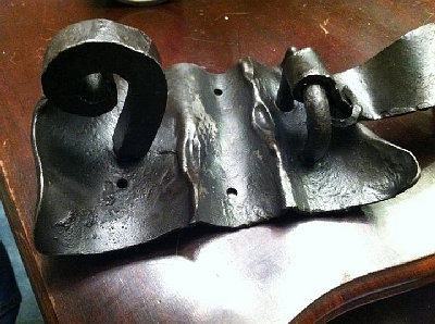
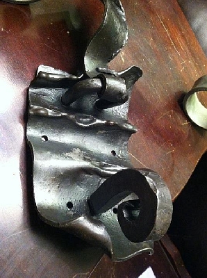
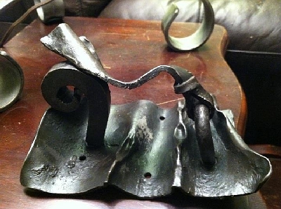
I was out in the shop this evening plinking away on bottle openers (this is what I do while I'm trying to decide what I'm doing) when I spotted a stack of 10 gauge sheet rectangles a friend had dropped off at my shop six months ago. At the time I didn't know what to do with them but they where an interesting shape so I tossed them on the pile and promptly forgot about them.
I had recently read through an article on fold forming in an old blacksmithing mag I had lying around so I decided instead of getting into anything purposeful I'd do a little "free play" this evening and popped one of the sheets into the fire.
After doing a few experimental folds and finding myself pleasantly surprised at just how organic the results where, I ended up with a partially folded plate that looked like it wanted to be a door knocker.
-
IForgeIron.com Blueprints
Copyright © 2002 - 2012 IFORGEIRON.COM, All rights reserved.
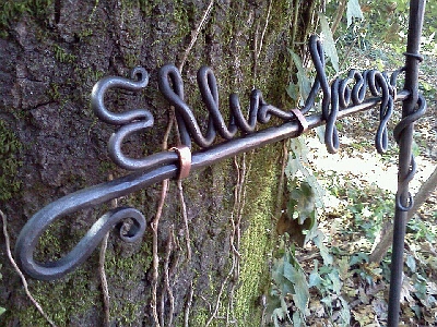
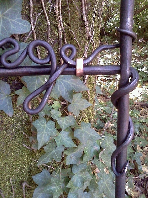
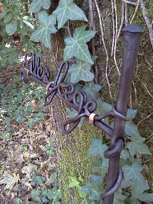
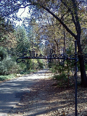
BP0813 Sign Design
by Arean Ellis
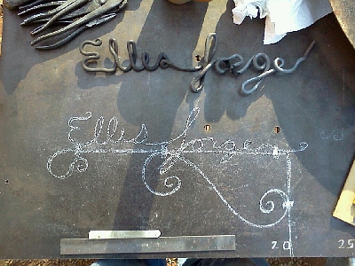
Here is my best design so far...
Any other ideas or changes you could think of making? I'm having a hard time settling on any one idea. Nothing seems to fit the lettering as well as I would like. I'm tempted to go with a vine theme...but am worried the final product won't turn out as well as I would hope.
I'm using 5/8th round for the main 'trunk' and 3/8 round for the scroll. The lettering is 5/16 round.
The finish is bee's wax and boiled linseed oil.

-
IForgeIron.com Blueprints
Copyright © 2002 - 2012 IFORGEIRON.COM, All rights reserved.
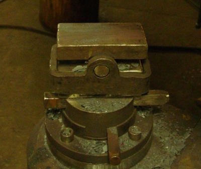
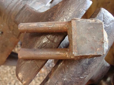
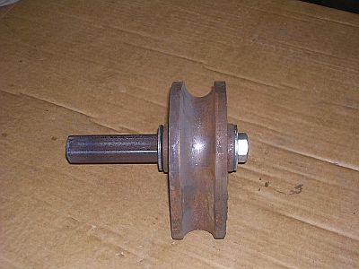
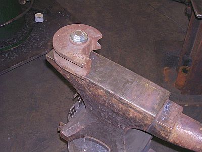
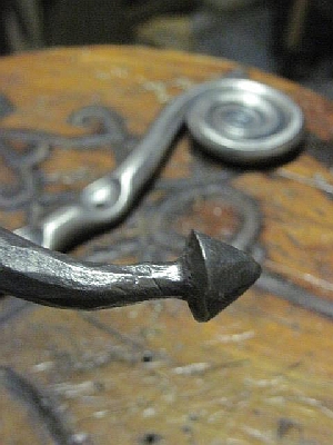
BP0814 PH Taper tool
by Timothy Miller
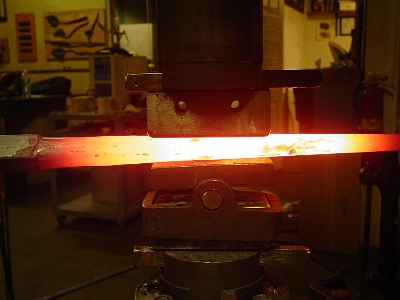
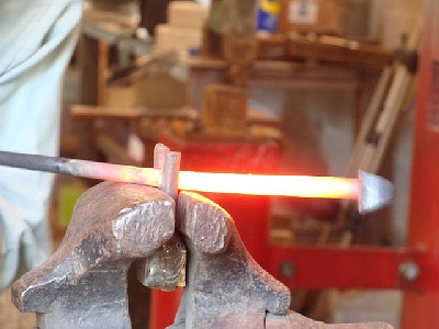
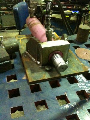
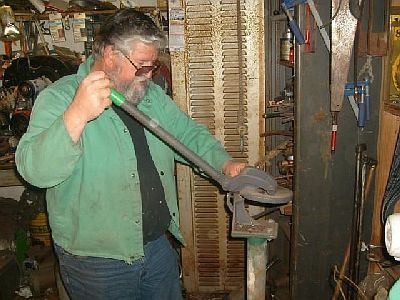
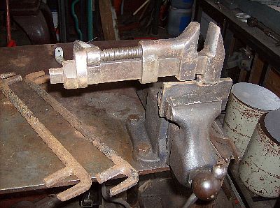
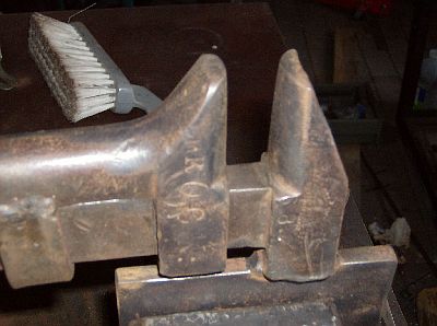
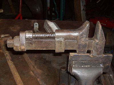
I made this tool because I forge a lot of tapers that later get ground and polished so the smoother they come off the hammer the less work for me. it consists of a hot rolled steel plate the same size as the die with a piece of 1" hot rolled round welded to the bottom as a pivot. The pivot contained in a frame that slips over the bottom die. It pivots to the angle of the taper and produces a smooth finish. I used hot rolled because I don't want it to damage my dies. I have to rebuild it every few years but it is a very useful tool. Shown is a taper drawn out from 1 1/2" square steel 24" long down to 3/4".
Ah yes, The pivital round back flatter- Nice!
Normally do 30 or more tapers in a run. I use the "drawing dies" that Tom Clark sold with the hammer to draw out the steel. They are about 2" wide with a gentle curve to the face. I measured the curve it works to be about a 3.5" radii. It seems to be about ideal. It is worth my time to change out the dies as the drawing dies seem to be about 30% or 40% faster and leave a better finish on the part. Then put the flat dies in for finishing.
Thomas Powers
First time I've seen the bottom version of that tool. Most folks I know have a handled top version with the flat face and a rounded back so the top die can always find a place in line to hit it. You can also use it without having to switch in a bottom tool.
Timothy Miller
Like I said It was not original to me but It has saved me a lot of time over the years. I think that people who never saw it before would benefit from being introduced to the idea. I also suspect it is a very old idea as well. The idea came to me from Fletcher at arrowmount metals originally he suggested a round back tool as well mated with a corresponding bottom die. He is sort of the Grant Sarver of the east when it comes to tooling. I also have seen Dicks Sargent's tool and another version at the Memphis metals museum. I claim no ownership over this idea and I give credit where credit is due.
Thomas Powers
I break out in hives when folks try to claim *first* on a lot of smithing stuff as there generally is a lot of re-invention of the wheel in this craft; especially by people not steeped in the historical aspects of it...(I've had an amusing time telling some "traditionalists" that the first powerhammer I've documented was in use before the year 1000...).
What I tell folks is to work on being *best* not first.
It sure helps the craft as a whole to have people showing off their version of various tooling with any improvements they have thought of even if someone else somewhere somewhen has done it before.
I enjoyed reading "Practical Blacksmithing" a series of articles from a smithing Journal (magazine) from the late 19th century which is full of "this is how I do it or what tool I made to do the task mention in a previous issue that I think is *better*!"
It is a good idea however to mention who you got the idea from; but not necessarily as the *inventor*---"I got this idea from a frazzlewhopper that I saw in Dismas of the stone cold forge's shop that he had made to do the same task. -
IForgeIron Blueprints
Copyright 2002 - 2011 IFORGEIRON, All rights reserved
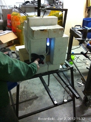
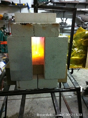
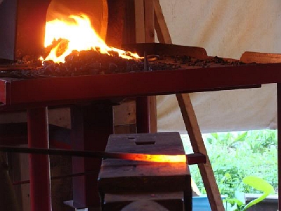
BP0816 Brick Forge
by Kraythe
Over the time I have been visiting this forge I have seen a lot of people come through and ask about all sorts of designs of forges. Most of the people posting such threads are actually new to using a gas forge and often new to smithing. I have advised many of these newer smiths to first build a brick pile forge, use that a while and then go to something more serious once you figure out how big you will need. So now I wanted to make a definitive post as a guide for these people.
The forge will have an internal size of 9" x 4.5" x 6.5", or 263 cubic inches. It is, however, easily reconfigured to be smaller, shorter, wider or whatever you need for your particular tasks in the shop. That is the beauty of a brick pile forge, it can be reconfigured at will and allows the smith to see what size they need in the end. This forge is not the end all-be-all of smithing forges. It is a starter forge and as you work with it, you will learn a ton about how forges work and will grow into more efficient systems. The brick pile forge is so versatile that occasionally I will toss one together just to do some specific task that doesn't work well in my main forge.
Forge Materials:- About 10 to 15 Soft insulating bricks, rated 2300 degrees farenheit.
- 3 Hard firebricks.
- Metal Table
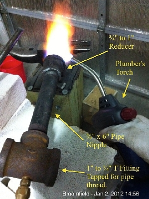
Burner Materials:- 1" to ¾" Black Iron T fitting (1" across the top and 3/4" on the leg of the T)
- ¾" to to 1" Black Iron reducer
- ¾" x 6" Black Iron Pipe Nipple
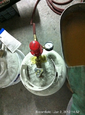
- High Pressure Propane Regulator
- Propane Pressure Gage
- ¼" Propane Rated hose with Fuel Threaded ends (available at welding supply stores)
- ¼" Propane Rated Flashback Supressor (available at welding supply stores)
- ¼" Fuel to normal pipe thread converter (available at welding supply stores)
- ¼" Ball Valve
- ¼" Brass Pipe Nipple (4")
- ¼" Brass pipe Nippel (smallest)
- ¼" Brass Pipe Straight Connector
- ¼" Brass Pipe to 1/8" Copper Compression Fitting
- (2) ⅛" Brass Pipe Compression nuts
- 24" flexible copper pipe
- ⅛" Compression to normal pipe Nipple
- .025 MIG Tip
- Propane rated thread sealant.
Tools (Basic):- Copper Compression Hose Flare Fitting
- Tap for your MIG tip thread (varies by the tip brand)
- Tap for ⅛" pipe thread
- Couple of Crescent Wrenches
- Drill
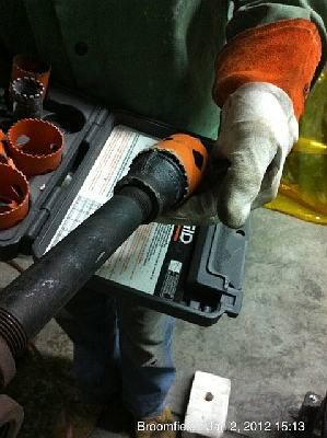
- 2" Hole Saw
- Hacksaw
- Reducer for ¾" to drill bit size for the tap.
- Plumber's torch with click starter
Tools (Best):- Drill Press rather than drill
- Dremmel with Cut-off wheel
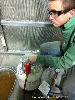
Propane Supply Assembly
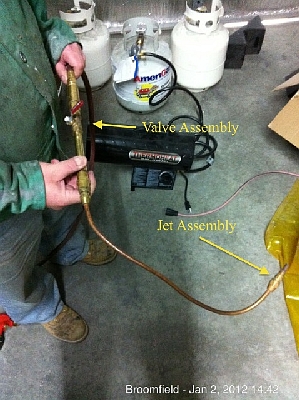
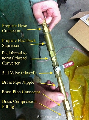
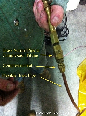
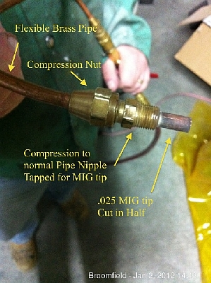
First tap the 1/8" compression to normal pipe nipple with the tap for your MIG tip. The right tap to use depends on the tip brand that you are using. If you ask a welding supply store they can supply you (or at lest tell you) the right size. Then cut about ⅛" off of your MIG tip and put propane sealant on the threads and screw it into the tapped fitting securely. Next attach the copper flexible hose to the compression fitting by putting on the compression nut and then flaring the tubing and finally screwing the compression nut on the fitting you tapped. The goal of the flexible copper tip is to get a good nice gas tight seal without constraining yourself with rigid pipe. Next put the compression nut on the other side of the tubing and flare that. Take the ¼" pipe to compression fitting and attach the other end of the flexible copper tubing to this fitting. Then attach the converter fitting to a small pipe nipple then to the straight connector and then to the longer pipe nipple. The extra parts make this assembly easy to use on other burners and other projects in the future. Finally attach the 4" brass pipe nipple to the ball valve, then attach the ball valve to the fuel to pipe thread converter. use propane sealant on all threaded connections.
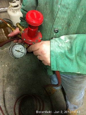
Fuel hoses are backward threaded. You learn "Righty tighty, lefty loosey" to understand normal threads. Fuel threads are the reverse of that and this is a safety feature that you don't want to violate. The converter changes the normal pipe thread into fuel threading. This should be screwed right into a propane rated flashback suppressor. This device will keep a flashback from reaching your bottle if something should go badly wrong. You can potentially skip this device but when it comes to exploding propane bottles, I prefer to play it safe. Attach the flashback suppressor to your propane fuel hose and then the other end of the fuel hose to the regulator. Screw the pressure gage on the regulator and you have the jet assembly done. Again remember to use propane sealant on all threads, if you didn't, go back and take it apart and do it right.
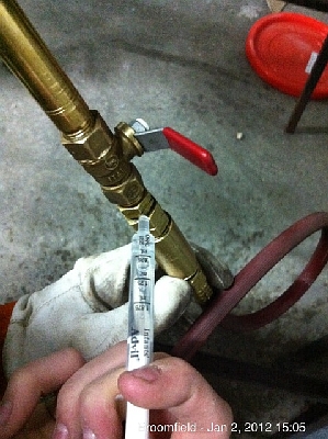
Burner
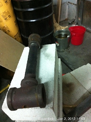
The burner is a standard "Frosty" T burner so named after the forum user Frosty who created it and has a propensity for wrestling large trees.")
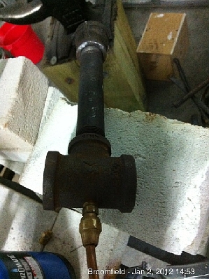
To tap the back of the T, get a reducer that will screw into the ¾" side part and reduce it to just barely the size of the drill bit you will use for the pipe thread tap. If it is smaller, that is fine, if larger that isn't optimal. This reducer will serve as a guide to the drill to position the jet exactly in the middle of the T leg. Drill out the burner and then tap it for the ⅛" pipe that the MIG tip is attached to. Next attach the black iron pipe nipple and the ¾" to 1" reducer to act as a flare.
If you don't know how to drill and tap, then you should probably research that and practice before embarking on this project.
Now screw the burner jet into the burner and then test the burner.
Testing the Burner
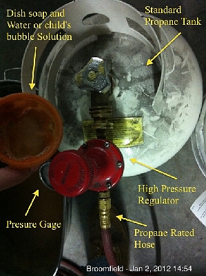
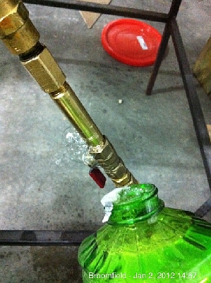
Check for leaks using dishwashing fluid mixed with water or, even better, child's bubble solution. If you see bubbles that is a leak. Twist it tighter, make sure you have a good amount of propane sealant and so on. Light the burner with a plumber's torch (this is the safest way to light your forge). Another great trick for checking leaks is a cheap medicine syringe used for children. Fill it with bubble fluid and squirt on your junctions. Note that while I am testing my son is sitting there with his hand on the bottle valve and watching what is going on. His job is simple, if something goes bad, he cuts the propane at the bottle.
Forge
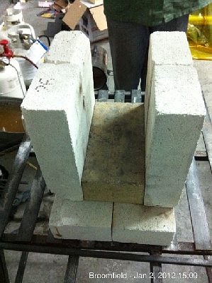
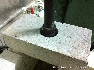
When we say brick pile, we aren't kidding, its literally a pile of bricks on the table. Use a metal table and you can fabricate one if need be. Mine is fabricated to hold forges. Start with three bricks in the center of the table configured as shown
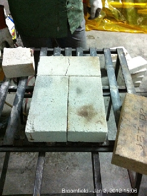
Add a hard firebrick in the middle. This will heat up in the forge and serve to regulate the forge temperature. Make sure the brick is at least the width of one brick from front, back and sides.
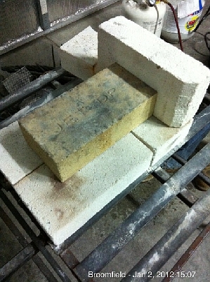
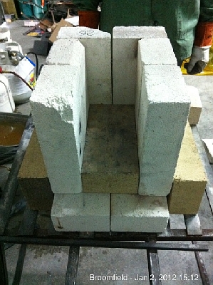
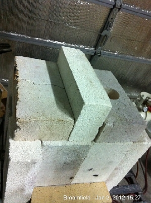
Next add vertical bricks to the side of the hard brick.
Now we test out the roof bricks. We want to make sure that we have the right width.
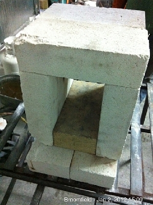
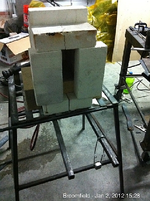
Now we add some hard bricks to the side to support the vertical bricks from falling. We also set up a couple of bricks to serve as the back door.
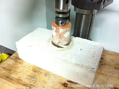
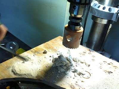
Now we have to drill out one brick for the flare. These bricks are very soft so be careful or you will shatter them. We use a hole saw to drill the brick. Put plywood under the brick to support it and make sure you can drill all the way through without hitting the table. When you drill, go very slow and steady. Don't press hard or the brick will shatter.
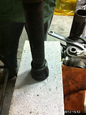
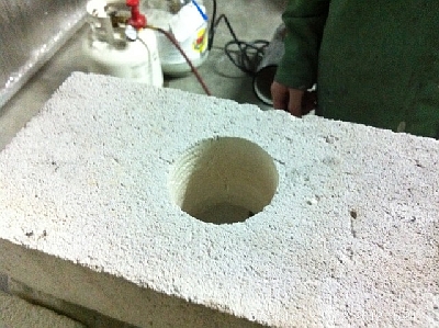
Now we place the flare brick on top of the pile, stick the flare through and clamp up a support for the burner. The bricks won't be strong enough to support it.
Now we seal up the roof using a brick on edge to serve to give a roof over our front door bricks.
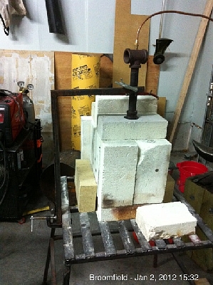
Finally turn on the burner to about 5psi and open the ball valve while the plumber's torch is in the forge and enjoy the glow.
Enhancements:
The bricks can be coated with ITC-100 wherever they are exposed to heat. This will make the forge hold a lot more heat. You can also make a quick form the size of a brick and pour half an inch of castable over the brick (like Kastolyte 30) and then coat that with ITC-100. Make sure the first time you fire the castable you go slow. This will allow a much hotter face. You can put in blown burners, change the configuration and a dozen other enhancements. -
IForgeIron.com Blueprints
Copyright © 2002 - 2012 IFORGEIRON.COM, All rights reserved.
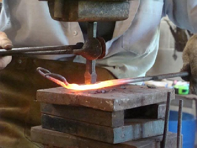
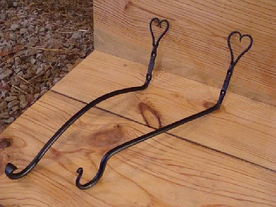
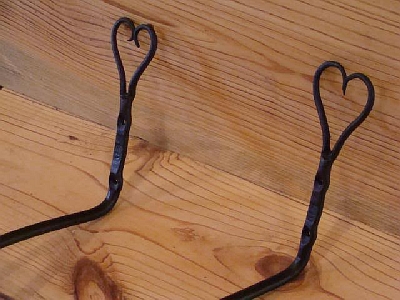
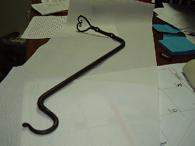
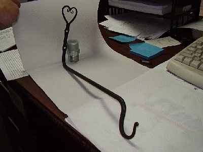
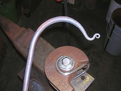
BP0815 Heart Hook
by Dave Custer
as requested, here is a step-by-step tutorial of my heart-themed bird feeder hook.
I should have mentioned this before, but these step-by-step instructions do not cover pieces I claim a copy right to. Anyone here is welcome to try to reproduce these piece. I encourage you to come up with your own variation and exercise your own imagination in your work, but if you are hard up for ideas, don't worry about copying what I'm doing! You are MOST welcome to try it.
I sell this piece as a bird feeder hook. The idea is, the extended hook gets a bird feeder, or hanging plant, or dinner bell, or WHATEVER, away from the post, beam, or board the hook is mounted on.
This tutorial will cover two variations of the bird feeder hook. One is a simple J-hook style and the general shape and forge work would be classified as a beginner level project. The second variation features a flared scroll type hook with a (supposedly) graceful curl down to the scroll. This might be classified as an intermediate level piece as it is much more difficult to get an even, "kink free" curve, than it is to make the simple "cut-n-dry" shape of the first variation.
Step #1: Turn off the TV, hit the shop, and cut you a 20-inch piece of 3/8" round stock.
Step #2: Mark a line with silver pencil or soapstone, 2-inches from the near edge of the anvil. Heat the end of the stock, place the end of the stock against the line, and step the metal to one side. You will use a half-on-half-off hammer blow to accomplish the step in your metal. Basically one side of the metal will "step" down and the other side will remain flat. In this entire process, keep the metal VERY hot the entire time. Just shy of welding heat is IDEAL. If you over-stress the metal from lack of heat, you WILL loose your heart. (The metal one that is!)
Illustration of a half-on-half-off blow. (cold)
During the process!
The result!
Step #3: Now center punch the stepped in side of the stock a couple of times. These will act as guide marks as you split the stock. Make sure they are in the center. I just eyeball it, but if you want, you can measure or use a center finder.
Step #4: Next heat the end of the stock and using your center punch marks, split the stock with a chisel. HEAT IS KEY! LOTS AND LOTS OF HEAT! The heat must be, not only on the end of the stock, but back in the shaft behind the step on the end. Chisel up to the end of the step. A cherry red heat is NOT ENOUGH! BRIGHT red is the lowest you can go and ideally you need to keep it in the yellow to bright yellow range! I HIGHLY recommend a cutting plate for this job. I use 16 gauge sheet metal to protect the anvil face. Some people use copper! You may be the best "chiseler" in the world, but you WILL miss eventually and your anvil face will remind you forever. Spend ten cents and buy a cutting plate!
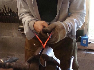
Step #5: After you have chiseled completely through, use your hardy to seat the cut and spread the two prongs apart! Once again, LOTS AND LOTS OF HEAT!
(That picture shows you the IDEAL working heat and location of that heat for the entire "split heart" forging process!)
The result of this seating and spreading should look like this!
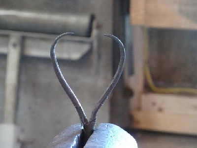
Step #6: Next, one prong should be straightened and one should be curled back as shown below! Make sure you don't let the stock twist when you curl the prong back. It will try to twist, but keep it straight and again.....HIGH HEAT! Also, you'll probably have one prong that is a little bigger than the other. Bend the larger of the two out of the way and leave the smaller one straight. This makes it just a bit easier to get the prongs the same length. (This curl is called a convenience bend.)
Step #7: Taper the straight prong using your preferred tapering method! Then make a mark on the anvil that designates the length of this prong. This mark is VERY IMPORTANT in making an aesthetically pleasing heart.
Step #8: Now bend the tapered prong out of the way and straighten the other prong. Once again, watch for twisting and DON'T let it happen. Lots of HEAT! Then taper out the prong. Taper the prong to the length of the mark you made. That way, it will be near the length of the other prong. When you are done tapering, straighten the first prong and hammer the two together.
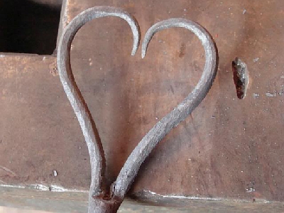
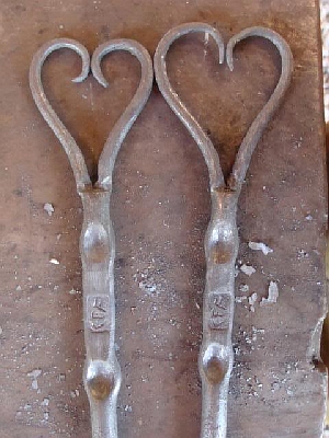
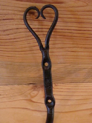
Step #9: Heat the two tapered prongs up, clamp the stock in the vice and use some needle nose tongs or pliers to begin shaping the heart. Use as many heats as you like, but try not to flex the base of the heart too much.
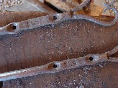
Step #10: Now it's time to make the screw hole locations. I do two screw holes, and I space them far enough apart to allow my touchmark between the screw hole locations. I use a ball peen hammer to make my screw hole indentions, then I flatten a place between the two for my touchmark. I place my touchmark, straighten it all back out, and let it cool. AIR COOL!
Step #11: After the metal is cooled, drill two 3/16-inch holes in your screw hole indentions. The advantage of the ball peen indention is that it eliminates the need for center punching or counter sinking your screw holes.
This is where the variations come in. I'll do the simple version first and then the more complex one.
Step #12: Taper the end apposite the heart.
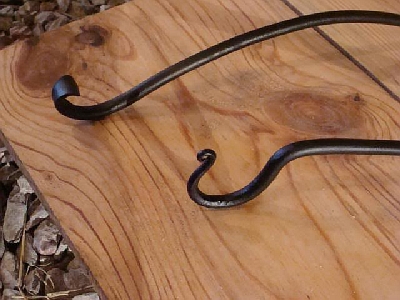
Step #13: Put a finial scroll on the tip. The scroll should face downward when the heart is facing upward. Then bend a hook on the tapered end. The hook should face upward when the heart faces upward.
Step #14: Bend this hook downward, approximately 90 degrees using the vise. (pictured cold)
Step #15: Now heat and bend the bar approximately 90 degrees, just below the last screw hole. This is done in the vise with the screw holes clamped in the vise. (again shewn cold)

Step #16: Wire brush a apply bee's wax while hot.
Now for the more difficult variation! Ignore steps 12-16 and pick up at step 11.
Step #12: Flare the end of the bar apposite the heart. For a wide flare use the cross peen hammer. For a medium flare us the edge of the hammer face. For a small flare, simply flatten the end of the bar. Scroll the flare so that the scroll faces upward when the heart faces upward.
Step #13: Bend the hook at approximately 90 degrees, just below the last screw hole. Clamp the screw holes in the vise to bend as shewn.
Step #14: Use a vise held bending fork to bend the bar, between the screw holes and the flared end, to a nice even curve. This takes practice so don't fret if your first isn't all that great. Work out any kinks and make sure the curve is even.
Step #15: Wire brush and apply bee's wax while hot.
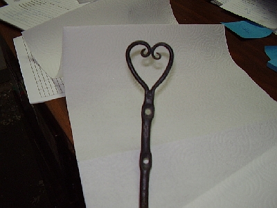
The end results!
And that's all folks! I welcome questions and comments. If something didn't make sense just let me know and I'll try to explain it better and/or get more pictures!
I think the BP's are more for focusing on a single technique or tool instead of a craft fair hook!
Curley George
No, BPs are for teaching/learning new things.
Randy478
Here are the pictures of the heart hanger I made yesterday. Randy
DaveRevision.....REVISION!
I was in the shop yesterday and a different method for step #5 dawned on me.
In step #5 I have you opening the split ends on the hardy. This pushes both of the prongs to the side, but we actually need one prong to stay straight. More movement in the prongs = more stress!
So this is the revised version of step #5.
Step #5 Clamp the material in the vise and use a narrow profile chisel to seat the split. Then us a tight radius, hand-held fuller to round the bottom of the split!
This method stresses the metal MUCH LESS than the hardy, and it gives the base of the heart a VERY NICE finished look that is more difficult to get with the hardy. It takes no more time than the hardy method and in fact saves time because it reduces the chance of breaking off a part of your heart.
It is such a pleasure and an honor to know that some of you guys are able to follow, successfully these instructions. I hope you all are enjoying putting your own "twist" (figuratively and litterly) on something that I make. I'd love to see pictures of the ones you are turning out and even variations of what was in the instructions.
-
IForgeIron Articles
Copyright 2002 - 2012 IFORGEIRON, All rights reserved.
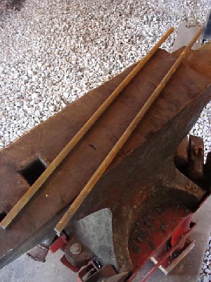
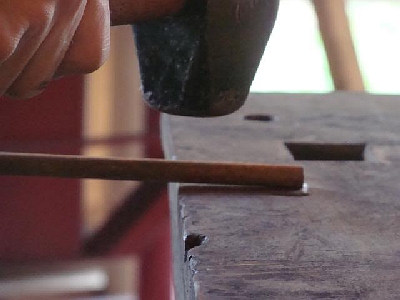
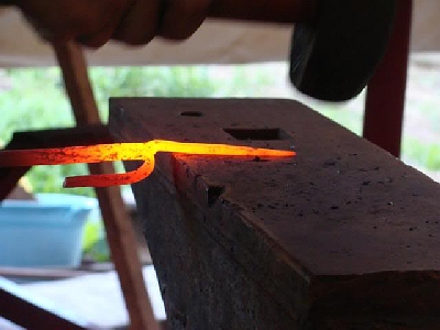
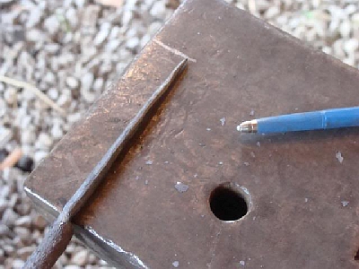
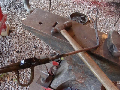
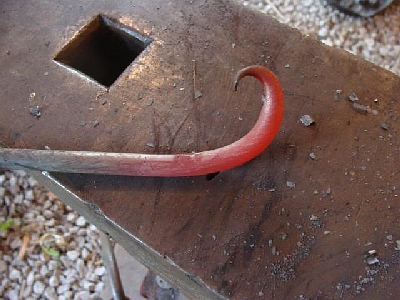
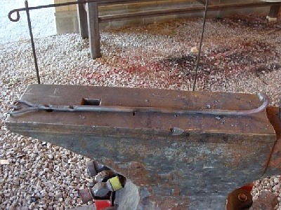
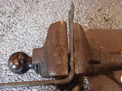
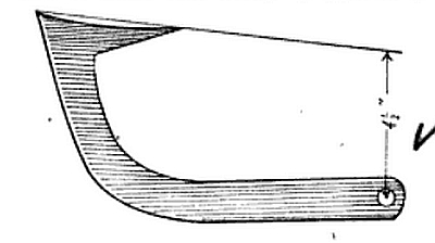
BP0817 How to make a Cant Hook
by A. Wood
I work in a lumber business where we handle all logs from pine up to 30 inches, so will give my experience in making hooks to give good satisfaction. I have followed this kind of blacksmithing for fifteen years. In the first place, making a keading tool out of stock 4 by 5/8 of an inch and 1 foot long. Punch a hole 1 by 1/2 inch in center of the piece and cut out the end you are to have your bill on, say about 3/8 of an inch deep at the hole running out to nothing at the distance of 3-1/2 or 4 inches from the hole. Cut ir out rounding is you wish a duck-bill, and tight down to a point if a diamond bill. Now your tool is ready to use.
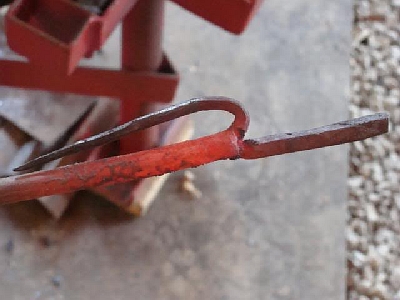
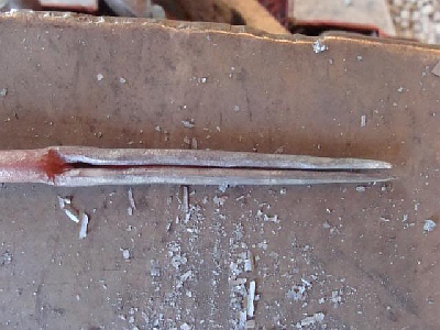
Cut your steel for a good, heavy head 20 inches long from 1 by 1/2 inch stock and upset one end until your piece measures 15 inches, keeping it straight on the back and duing all your upsetting towards the bill. Then heat and drive down with a sledge into your tool, being careful to draw your steel towards the heavy side so as to form the bill. In drawing down your will get wider and when you have it down 1-1/4 inches from the face of your tool to top of bill, corner it up on the horn of the anvil, always drawing towards the point which is drawn out in this way and diamons shaped to a point.
Leave the back of the bill hollow in center when you put straight edge on, so it will come out of the timber easily. Now that the bill is made, dress and even up all around and punch hole for 7/16 inch bolt in other end. Then bend the back of the hook round, leaving it a little straight at the end in which you punched the hole. Now take your square and place your hood in the corner and bend back so it will measure 4-1/2 inches from the center of the bolt hole to the line of the head. Your hook will handle logs up to 30 inches. If your timber is larger than this use more stock and upset same amount for head according to the size of logs. I hope this may help out brothers in the mountains to make hooks.
I remember the time I used to sweat over them, and would have been pleased to have the paper come to my rescue in many others hobs as well as hooks. I am greatly pleased with our paper and derive much benefit from it.
A. Wood
-
IForgeIron Articles
Copyright 2002 - 2012 IFORGEIRON, All rights reserved.
BP0818 Ribbon Burner
by Kraythe
Author's Note: This thread talks about activities and techniques that are DANGEROUS. You use this information at your own risk. I suggest you read the entire thread before embarking on the build. It should be noted that is not a project for a beginner. Look into brick pile forges and building venturi burners to get some experience before tackling something like this.
In my previous thread "Ribbon Burner Build" I created a square ribbon burner and learned a lot of things about what makes these things work. One thing that I neglected to include in my calculations was Bernouli's Principle; which states that a gas exiting a small tube into a large tube results in a larger pressure in the bigger tube but slower velocity. When we consider a ribbon burner, this means that the plenum doesn't need to be pressurized by back pressure building in the burner but rather its a natural result of the principle. What it also explains is the performance of the final burner. The numerous 5/16" holes on the exit of the burner are essentially one exit pipe since all will be backed by the same plenum pressure. So applying the principle we see that our 14 holes 5/16" wide comprise an exit pipe about a third of the input pipe. Applying Bernouli's principle it is clear that this means that the exit from the plenum will be three times the velocity (and a third of the pressure) of the gas inflow. Thus the reason that the burner has such a high velocity and hard time staying lit. Furthermore, since each jet is a flat casted tube, the burner lacks the dynamics of the traditional burner's flare to slow down the gas and balance flame front velocity.
Another lesson learned is the cumbersome nature of a square burner. With the square burner, the forge dimensions must be accurate on all four sides to accommodate the burner. This leaves us with precious little tolerance for fitting. A perfectly round burner would work better. Additionally the structure of burner requires that there is little contact surface between the castable and the burner itself, only a small ridge and ¾" of metal around the edge. This will weaken the burner's ability to handle thermal shock. Also with the way it is cast, the square burner is prone to error in the depth and efficiency it is set in the castable; if a builder makes a small adjustment or the castable doesn't flow and resettle over the burner properly, it won't work properly and could break.
A potential castable failure is another problem of that design. With the manner in which it is cast, a catastrophic castable failure would result in a complete failure of the plenum enclosure and thus a very bad result. as propane is dumped in at high pressure. The forge could suddenly burst in propane resulting in bad consequences. So clearly we need to work on a superior design.
Thus is the Three Inch Round Pressurized Plenum Multi-Jet Burner (Ribbon Burner) Born.
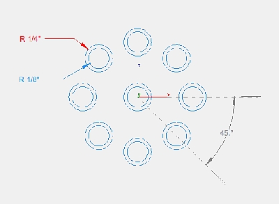
I started on my cad system planning the Burner. I planned to use a 3" inside diameter pipe (3.5" outside) as the size. The burner would be fed by a 1" feed tube and would be built to learn all the past lessons. The burner will have 9 jets that are ⅜" in diameter with ½" flares for each jet. The reason for the calculation of size results from the calculation of feed pipe input to burner jet output pipe size. So I wanted to make sure the jets comprised at least the same area in sum as the feed pipe. The calculation is fairly simply derived from the formula for the area of a circle. Area = πr2. So we want to know how many pipes of diameter x will take to equal a feed pipe of diameter y so: π(y/2)2 / π(x/2)2 ==> (y/2)2 / (x/2)2 ==> (y2/4) / (x2/4) ==> (y2/4) * (4/x2) ==> y2 / x2. From the complex we derive a simple equation courtesy of a little algebra. Putting the numbers in for a 1" feed pipe and a ⅜" output pipe, we get 12 / (⅜)2 ==> 1 / (9/64) ==> 1 * 64/9 ==> 7.111111 jets. So we would need 8 jets to accomplish a jet total diameter equivalent to the feed pipe.
Wow. Is Everyone's brain hurting now?
Stuffing all of this into my CAD system you have the following Burner.
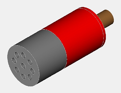
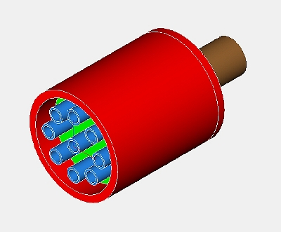
You may note that I included not 8 but 9 jets. The reason is that I wanted to make sure I really had enough output flow to slow it down. In retrospect I might have gone with 8 or even 7. Although the burner works good with 9, as you see later it seems to lack a little velocity.
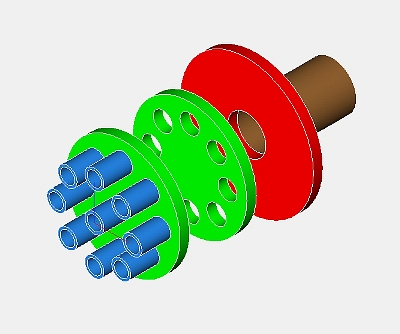
This is a pretty spiffy model but how do we construct it in real life? Well those that use CAD systems know that the easiest way to do a model like this is to whip up a cross section, create a single object from it and then extrude that cross section for the 3d model. I did exactly that and here are the cross sections for the Baffle, Flare and metering plate respectively.
The fuel/air mixture enters through the feed pipe in the back then passes through the baffle which is designed to cause turbulence in the stream and make sure the mix is as complete as possible. The fuel/air is then forced through the metering tubes and is forced out into the flare. The flare jets are half inch in diameter, which is the outside diameter of each metering tube. The casted flare will now grip the metering plate, and the edge of the plenum as well as the wall of each of the metering tubes. The metal metering tubes also are a safety mechanism. If the flare were to crack catastrophically and drop into the forge, the metering tubes would still be working as jets and give you time to shut down the burner safely rather than a whole mess of pressurized propane bursting into the forge.
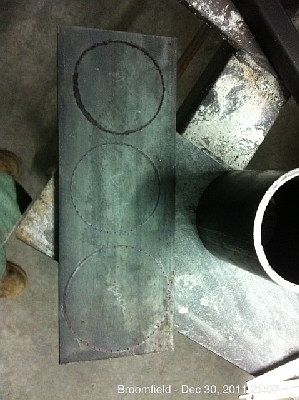
To build this burner I selected 3" inside diameter ¼" wall mild steel pipe with ¼" x 4" wide plate to use for the baffle, metering and back plates. The metering tubes are ⅜" inside diameter by 1/16" wall tubing equaling ½" outside diameter. The very heavy materials will let us repeatedly recast the flare as needed. We can even hit a damaged flare with a hammer to break it off due to the plenum's strength. Now its time to build it.
We start by cutting 4" of the pipe to serve as the plenum and 12" of the ¼" x 4" flat stock.
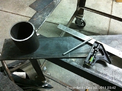
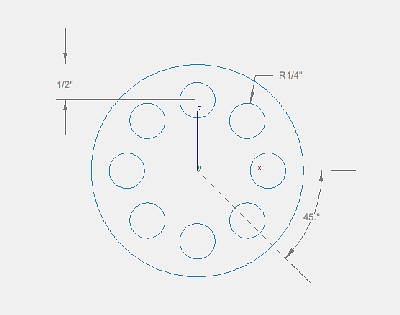
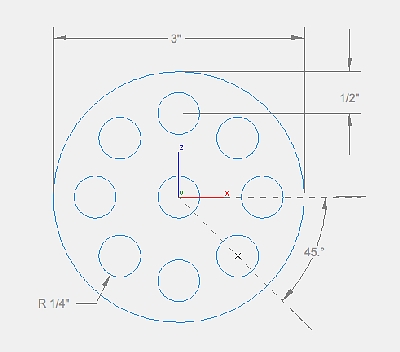
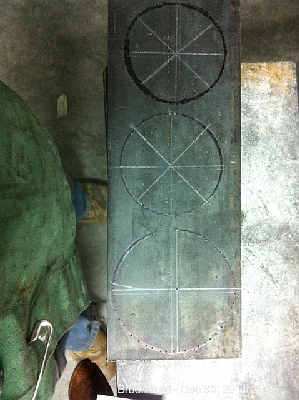
For the baffle and metering plates we trace the inside of the pipe on the flat stock with the welding pencil. For the back plate we trace the outside of the pipe.
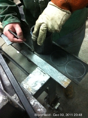
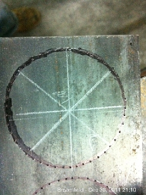
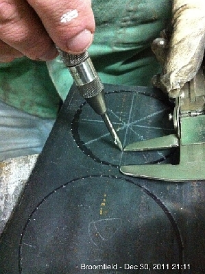
Now we take a center punch and clearly mark the drawn circles with push marks. Later when working with the plates, we will be putting the metal under a lot of heat and the pencil or chalk lines could rub off. The punch marks will endure despite OA torch work or anything short of grinding them off. Also note that if you don't have a welding pencil, a permanent marker will do the trick. I have marked over my welding pencil lines in the images with the marker to demonstrate. Use a thin marker or your lines will be erratic.
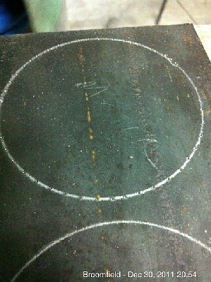
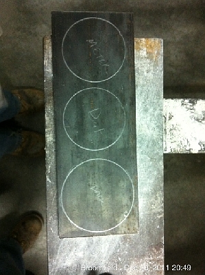
Now the task is to find the middle of the circle and then draw the 45º angle lines which will help us align the punch marks for drilling the holes. At this time I was estimating the best I could for how to do the center so it was slightly off. A day after I had drilled everything I found a geometric and easy way way to find the exact center of any circle. I will talk about that method later so don't start marking yet. My marks were reasonably accurate though I can see them a tiny bit off. I chose the best marked plate to punch for the metering tubes. I measured in along each line from the outside circle one half an inch and punched a mark. For the metering plate, I punched a mark in the middle as well.
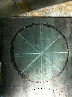
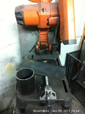
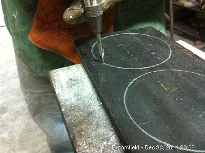
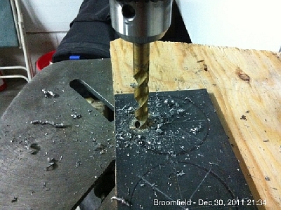
Now its time to drill the holes for the metering tubes and baffle. You might notice that i haven't cut apart the plates yet. You shouldn't either. The long plate makes it easy to clamp to the drill press securely. Clamping the individual circles would be very difficult. Drill first, then cut. When it comes to drilling I have put a piece of scrap plywood under the plate and adjusted the drill press to stop halfway through the plywood. That way I can make sure I get all the way through the metal as well as not hit my drill press table. I am using Dewalt Titanium drill bits because, frankly, they are awesome. You could theoretically do this with a hand drill but your accuracy will suffer badly. If you don't have a drill press, borrow one.
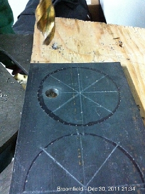
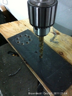
Now its time to cut the hole for the feed pipe in the back plate. A bimetal saw will do this as long as you have a good lead drill bit to guide the hole saw. This will generate a TON of noise and vibration and so I recommend you put on as many clamps as you can and put them on tight. Unfortunately my hole saw rig was damaged and I couldn't use a lead bit. As a result the hole saw wandered off center and skipped a bit. The result would still be acceptable as the burner doesn't have to be centered. However, I am something of a perfectionist for this and I will correct it later.
22


Now we can separate the plates first with a chop saw and then with an OA torch we rough cut out the outer circle of each plate. After that we use an angle grinder and clamp each plate in a vise and then grind down to the dots we punched for the circle (all welder's pencil and ink marks will be long gone). We just keep grinding down and turning the plates in the vise until they are right. To make sure they fit, test fit them in the pipe and grind down as needed. Don't forget to grind a slot for the seam inside the pipe. Then grind the plates clean and shiny for better welding.
25


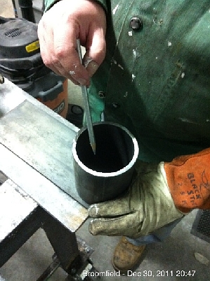
Now we can install the metering tubes. Cut off a 1 inch piece of tubing for each metering tube and then use a round file to clean off any metal burrs and grind a small bevel in one end of each of the tubes. Then take a hammer and set the beveled end in the metering plate and tap them down with the hammer but don't crush them. If they won't go, file out the hole a bit to make it work. It should be tight and take a hammer to set them but they should go in. Tap each tube down til it hits the metal underneath. All tubes should be flush with the back of the plate.
29


Now using a MIG welder carefully weld around the outside of the metering tubes on the back of the plate. Try not to fill in the tubes too much or you will be filing for a while. Make good welds. Although they don't absolutely need to be gas tight, if you can weld them that way, all the better. Once welded, use a grinder to smooth off the back of the metering plate flat. The picture shows this in progress. Next take a round file and file out the inside of each tube to round again to get rid of any weld material.
34


Now the metering plate is done. You can see the basic "Gatling Gun" structure and the lights from behind show the metering tubes are smooth inside and not obstructed.
37


Now we put the plenum on a flat piece of metal that is at least as wide as the plenum and drop in the metering plate facing down and make sure it is sitting flat. Then we gently tack weld the metering plate in place.
41


Now flip over the plenum and inspect it. The metering tubes should all be in flat with all tubes flush with the edge of the plenum. If it all is good then weld around the side of the plate to permanently mount it in the plenum. Take care to make good welds as gas tight would be beneficial. Try not to obstruct a tube with weld material or you will have to file that out with the round file. Its hard to brush off welds down in the pipe to make it look good but the principles of the weld are important, not its appearance.
44


Now we are back to the problem of the back plate. Recall earlier I had a problem cutting the feed tube hole. I decided to redo it and this time i used my new method to find the center of a circle. It seems that geometrically any chord of a circle can be used to help find its center. A line passing through the halfway point of any chord and perpendicular to the chord must pass through the circle. So once you have pushed the circle, take a ruler and draw a chord exactly two inches long. Mark the 1" center of that chord. Then using a right angle draw a line passing clear through the circle. I used a cheap $5 adjustable metal protractor from Home Depot. Repeat this process and where the two perpendicular lines intersect is the exact center of the circle. Neat huh?
47


I punch a mark at the center and drill a half inch hole (largest drill bit I have) in the middle. Then I draw out a one inch circle centered on the drilled hole. If you have a locking compass this should be easier to do before you drill out the center. Finally I punch the center circle with a center punch and then use the OA torch to cut it out. I file it as smooth as I can get it and then use the OA torch to cut the outside, and then grind it as before. in retrospect a Dremel might have made better work of the center but it doesn't have to be precise as turbulence is actually desired. I could have, of course, just bought another hole saw but now you have two ways to do it.
51


Now its time to install the baffle plate. We measure down 1" into the plenum and mark it with a welding pencil. Then my helper (my son) holds the plate with some needle nose vise grips at the lines and flat so I can tack it in. We check the fit and then weld it in permanently.
57


Next I weld the feed tube to the back plate. For the tube we used a 1" black pipe connector. Do not use a nipple or you will not have much material to weld to. Its better to use a straight connector for its greater metal mass. This weld MUST be gas tight and we will insure that later. Once this is done, we fit it on the plenum and then weld the back plate to the plenum. For this weld make sure you use high heat and probably two passes.
60


Next I pass over the back plate and feed tube welds with an OA torch with a number 3 welding tip. The goal here is just to walk the weld puddle around the plenum and tube. If there are pinholes, they will be filled. If there are voids they will collapse and can be filled from welding rod in your hand. We dipped it in the water to cool it off after it was black again. The dead cricket in the water seems to help.
63


Now I did something a bit boneheaded. Or rather ill timed. We decided to paint the plenum to resist rusting. Good idea to use an engine approved paint for 500º as the plenum shouldn't ever get that hot. So we crafted a box and painted it nicely. It looks great. Except we forgot later we will have to shove the thing in a forge and that will burn off our paint job. Oh well, live and learn. We will paint it again later when it is done.
67


And now the plenum is done!
73
Time to work on the flare. The flare will be cast out of Kastolyte 30 reinforced with stainless steel needles. In retrospect I might have used something a bit more dense but with the same rating. I don't know if a base of kastolyte with a Mizzou last inch would hold together. It might be worth a try. The problem is the kastolyte is an insulating refractory that is soft and the jets at the flare end might be prone to fracturing. Perhaps less jets and more space between jets would help. At any rate, to cast the flare we have to keep castable from getting inside the plenum and also cast ½" jets centered right over the metering tubes. We accomplished this by first trying to epoxy in ⅜" dowels into the plenum and then epoxying ½" dowels on top of the metering tubes. This is shown below but it didn't work well because it was nearly impossible to get the top dowels centered properly and remain perfectly vertical.
74


 http://www.iforgeiron.com/uploads/monthly_01_2012/post-15449-0-08575900-1326100251_thumb.jpg http://www.iforgeiron.com/uploads/monthly_01_2012/post-15449-0-06634000-1326100255_thumb.jpg http://www.iforgeiron.com/uploads/monthly_01_2012/post-15449-0-76869200-1326100256_thumb.jpg http://www.iforgeiron.com/uploads/monthly_01_2012/post-15449-0-14640100-1326100258_thumb.jpg
Back to the drawing board. We took our half inch dowels and sanded them off and drilled out or pressed out the ⅜" dowels inserted in the metering tubes. If they go inside that is ok because they will burn out later. We then throw the plenum in the forge and burn it clean, burning epoxy as well as wood. This is NASTY so have a good ventilation fan! Oh yeah, the paint didn't hold up to the forge.
84http://www.iforgeiron.com/uploads/monthly_01_2012/post-15449-0-79300000-1326100260_thumb.jpg http://www.iforgeiron.com/uploads/monthly_01_2012/post-15449-0-46513500-1326100262_thumb.jpg http://www.iforgeiron.com/uploads/monthly_01_2012/post-15449-0-18282200-1326100264_thumb.jpg http://www.iforgeiron.com/uploads/monthly_01_2012/post-15449-0-90857300-1326100265_thumb.jpg http://www.iforgeiron.com/uploads/monthly_01_2012/post-15449-0-65608600-1326100270_thumb.jpg
We then decided to glue the ⅜" inserts to the dowel rods first and let them cure 24 hours first. In the meantime we experimented with making a tool out of the tubing used on metering tubes and a drill press. We also tried using sandpaper like a lathe since we only had to take off 1/16". These didn't work as well. I am sure there is a better way to do this to keep the tube perfectly straight but I haven't found one. At any rate our glued dowels worked. One thing we would have done is to sharpen the "up" points of the dowels so the castable would fall easier in between the dowels later. Make sure your dowels clear the top of the flare by at least 3.5". We glue them into the metering tubes with two part epoxy and let cure at least 24 hours.
89http://www.iforgeiron.com/uploads/monthly_01_2012/post-15449-0-18364500-1326100273_thumb.jpg http://www.iforgeiron.com/uploads/monthly_01_2012/post-15449-0-33454500-1326100275_thumb.jpg http://www.iforgeiron.com/uploads/monthly_01_2012/post-15449-0-13876900-1326100277_thumb.jpg http://www.iforgeiron.com/uploads/monthly_01_2012/post-15449-0-61690000-1326100278_thumb.jpg
In retrospect would have also made a top plate out of thin wood with holes cut for the dowels for perfect alignment fit after the castable is poured. The pattern for the metering plate would have worked nicely with a larger outside diameter; for materials use the thin wood that you can get from the hardware store with a shiny side.
To create the form for the outside of the flare we will use poster board and duct tape. We cut a 5" long slice out of poster board and roll it around the flare so the shiny side is inside. It should roll around several times. Get it nice and tight and tape the roll end. Now slide the new poster board tube up the plenum to make a depth of exactly 3 inches from the plenum pipe edge to the top of the poster board. Its possible you might be able to use a shorter cast but this looked good for insulation reasons. We duct tape the form in place on the plenum then later duct tape to reinforce the poster board all the way up the form.
93http://www.iforgeiron.com/uploads/monthly_01_2012/post-15449-0-11096200-1326100281_thumb.jpg http://www.iforgeiron.com/uploads/monthly_01_2012/post-15449-0-68594900-1326100283_thumb.jpg http://www.iforgeiron.com/uploads/monthly_01_2012/post-15449-0-52303600-1326100286_thumb.jpg http://www.iforgeiron.com/uploads/monthly_01_2012/post-15449-0-26488400-1326100288_thumb.jpg http://www.iforgeiron.com/uploads/monthly_01_2012/post-15449-0-11366000-1326100291_thumb.jpg
Now its time to mix the castable. We put on respirators (this stuff is bad for you to be breathing) and then my son opens the can we store Kastolyte 30 in and scoops it out into a drywall mud pan for mixing. We then get a couple of handfuls of stainless steel needles that will help reinforce the castable and put them in the dry castable. Now we add water VERY SLOWLY to the pan using a small plastic cup. You will be astonished at how a few drops can change the mix. Put a very small amount in, mix it up like crazy and then very slowly add a thimble full of water at a time. The final consistency should be like thick peanut butter.
98http://www.iforgeiron.com/uploads/monthly_01_2012/post-15449-0-14796300-1326100294_thumb.jpg http://www.iforgeiron.com/uploads/monthly_01_2012/post-15449-0-04222300-1326100296_thumb.jpg http://www.iforgeiron.com/uploads/monthly_01_2012/post-15449-0-04222300-1326100296_thumb.jpg http://www.iforgeiron.com/uploads/monthly_01_2012/post-15449-0-88050000-1326100297_thumb.jpg http://www.iforgeiron.com/uploads/monthly_01_2012/post-15449-0-66642700-1326100299_thumb.jpg http://www.iforgeiron.com/uploads/monthly_01_2012/post-15449-0-33398000-1326100301_thumb.jpg http://www.iforgeiron.com/uploads/monthly_01_2012/post-15449-0-09435300-1326100303_thumb.jpg http://www.iforgeiron.com/uploads/monthly_01_2012/post-15449-0-83199100-1326100304_thumb.jpg http://www.iforgeiron.com/uploads/monthly_01_2012/post-15449-0-75986800-1326100307_thumb.jpg
Now its time to pour. Scoop out the castable and put it right on top of the dowels. If I had sanded them into cones like pencils on top, this would have been easier. Fill the form until its full. Periodically you will have to pick up the burner and rap it solidly against the table repeatedly. This will force the castable mix to settle and fill all gaps. The vibration tamping is important. Without this you could end up with large voids. Just pick it up, keep it upright and rap it against the table several times and add more castable until it is full and even a bit overflowing. Once the form is full you can put on the top alignment form (not shown) tap down the form until its flush against the top of the poster board tube (some castable may squish out but that is ok). Then rap the whole thing against the table a few more times to settle the castable around any rods you have moved.
http://www.iforgeiron.com/uploads/monthly_01_2012/post-15449-0-32338200-1326100309_thumb.jpg http://www.iforgeiron.com/uploads/monthly_01_2012/post-15449-0-21824600-1326100311_thumb.jpg http://www.iforgeiron.com/uploads/monthly_01_2012/post-15449-0-71490200-1326100312_thumb.jpg
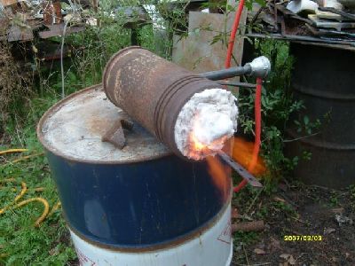
Now you have to wait three days; if its cold where you live, bring it inside where temperature is constant. After three days you can peel off the duct tape and unroll the poster board off the flare. This will let the bottom parts of the flare cure faster. Leave the top plate of the form in place as removing it now could crack the cast. After another day drying its time to bake it. Put the whole thing in a forge you have currently operating or a brick pile quick forge. It doesn't have to be that efficient of a forge. Put the flare in the forge when the forge is cold. Light the forge and let the thing bake. The wood dowels, top plate and epoxy will burn out. This will be NASTY so have good powered ventilation.
http://www.iforgeiron.com/uploads/monthly_01_2012/post-15449-0-51611700-1326100314_thumb.jpg http://www.iforgeiron.com/uploads/monthly_01_2012/post-15449-0-25494900-1326100316_thumb.jpg http://www.iforgeiron.com/uploads/monthly_01_2012/post-15449-0-04155200-1326100318_thumb.jpg http://www.iforgeiron.com/uploads/monthly_01_2012/post-15449-0-83693900-1326100319_thumb.jpg
Now we let it cool in the forge a couple of minutes and use a shop vac in blower mode to blow out ash and charcoal. Keep an eye on where embers go and put them out quickly. A friend helps for this part. Make sure you have a fire extinguisher handy if needed. DO NOT VACCUM THE EMBERS INTO YOUR SHOP VAC. If you do, you are courting a bad fire later. Eventually you might have one or two holes plugged. Use a spare welding rod or metal or whatever to clean it out. At the end you should be able to see smooth bores for the flare and the top of the metering tubes.
http://www.iforgeiron.com/uploads/monthly_01_2012/post-15449-0-56360600-1326100322_thumb.jpg http://www.iforgeiron.com/uploads/monthly_01_2012/post-15449-0-11851600-1326100324_thumb.jpg
Now we let the burner cool and very carefully, very gently touch any extraneous ridges with an angle grinder. The grinder will eat through the castable like it is air so be very gentle and quick. There may be some stainless steel needles on top of the flare but they will burn away later so don't stress over them.
http://www.iforgeiron.com/uploads/monthly_01_2012/post-15449-0-95648600-1326100325_thumb.jpg http://www.iforgeiron.com/uploads/monthly_01_2012/post-15449-0-55691200-1326100327_thumb.jpg
Now it is time to build the supply pipe. We take a ⅛" brass pipe plug and chuck it in the drill with the dimple side up. Make sure to get the ones with the centered dimple. It will save you some time. We drill a small hole for the propane jet. As will all blown burners the exact size isn't that important. Then we screw that plug into a straight connector, that into a pipe nipple, pass the pipe nipple through a 1" to ½" black or galvanized reducer and through a ½" inch brass plug that has been drilled out to be almost exactly the outside diameter of the brass pipe nipple. We attach the other end of the nipple to a ¼" to ⅛" reducer and an elbow.
http://www.iforgeiron.com/uploads/monthly_01_2012/post-15449-0-40184200-1326100329_thumb.jpg http://www.iforgeiron.com/uploads/monthly_01_2012/post-15449-0-14328900-1326100331_thumb.jpg
This assembly we attach to the supply assembly. This consists of a propane hose to the regulator attached to a propane flashback suppressor, then a fuel to pipe thread converter than a ball valve and finally a ¼" brass nipple to the jet assembly. Use propane sealant on all brass connections and check for leaks with child's bubble solution while pressurized.
http://www.iforgeiron.com/uploads/monthly_01_2012/post-15449-0-09318100-1326100333_thumb.jpg
Now we attach our blower (clamp it) to the a pipe to feed the air in. The feed plate is a 2" black iron pip nipple welded to a plate with a 2" hole in it. Then attach the blower feed to a bell reducer then to a gate valve using some pipe nipples and then to an elbow and then another long nipple.
http://www.iforgeiron.com/uploads/monthly_01_2012/post-15449-0-75465800-1326100337_thumb.jpg
The propane feed assembly is attached to the top of a T fitting, the pipe from the blower enters on the leg of the T and the nipple leading to the plenum is on the other leg. This setup allows you to adjust the position of the jet, though I haven't really noticed a difference so I will probably go down to a shorter brass pipe nipple in the jet assembly. Any space around the pipe nipple will leak fuel /air unless you seal it off with duct tape or something else. I am working on a better config that isn't so leaky.
http://www.iforgeiron.com/uploads/monthly_01_2012/post-15449-0-52264200-1326100339_thumb.jpg http://www.iforgeiron.com/uploads/monthly_01_2012/post-15449-0-78605800-1326100334_thumb.jpg http://www.iforgeiron.com/uploads/monthly_01_2012/post-15449-0-94779200-1326100340_thumb.jpg
Now we attach another elbow and then another nipple and then finally the plenum with its cast flare. We are now ready to test. We start a plumber's torch, set propane to 5 psi, turn on the blower and open the ball valve with the -
IForgeIron Articles
Copyright 2002 - 2012 IFORGEIRON, All rights reserved.
BP832 Hammer Technique
by Glenn Conner
Many have ask how to swing a blacksmithing hammer. This is the way I learned from Hofi.
Go to your anvil and put your hammer on the face of the anvil horn to heel. Walk up and grab hold with your thumb ON TOP of the handle. Now push - hard. You should feel resistance from your thumb to your hand, wrist, elbow, shoulder and neck. All the joints are effected in a BAD stressful way.
Walk up and grab hold with your thumb WRAPPED AROUND the handle. Now push - hard. Your wrist should bend absorbing some but not all of the stress.
Walk up and grab hold but use Hofi's technique. Best I can explain is to hold a sheet of paper vertically between the thumb and fingerprints. Hold the hammer handle the same way, between the thumb and fingerprints. Now push - hard. The hammer rotates between the thumb and fingerprints with no stress to your body.
The next step takes a little practice. Raise the hammer above your ear and throw it down toward the anvil, using the thumb and fingerprints to guide it to the hot metal. As the hammer hits it will rebound so catch it on the up stroke and raise it back to ear level. Repeat as needed.
Time to set up the anvil.
Adjust the anvil so the face of the anvil is level in both directions, side to side and horn to heel.
Go to your anvil and put your hammer on the face of the anvil, across the short side of the face, NOT horn to heel. Prop it up as needed so it stands in place. Now put the end of the hammer about mid-line of your body using your belly button as a guide. Reach for the hammer handle and notice that you put your body, shoulder, arm and wrist in a twist. Take a step or so left or right. Hold your closed fist about 3-4 inches from you leg so the hand touches the hammer handle when you walk up to the anvil. This puts your shoulder arm and wrist in the same plane as the hammer, and in a position so you do not hit yourself in the leg with the hammer.
Put a 1/2 or 3/4 inch piece of soft wood on the anvil face and hit it with the hammer. If the crescent is at 12 o'clock the anvil is too low. If the crescent is at 6 o'clock the anvil is too high. 3 and 9 o'clock means you are holding the hammer to the side or the anvil is tilted to one side and not level, or not parallel with the face of the anvil. Raise or lower the anvil as needed to get nice circles upon impact. Or raise or lower the ground you stand on. Either way watch the crescents.
You do not have to take a full swing if you need a light blow. Many people are afraid to use a full swing and never get a full force hammer blow. Raise the hammer above your ear and swing or throw it down toward the anvil, with full maximum force, You can use a wooden stump, or a piece of wood on the anvil face, but swing the hammer as if you were going to drive it 2 inches below the anvil face. This means you DO NOT pull your hammer blows, or slow down just before impact. You drive the hammer into and though the hot metal. CAUTION: This also means that the anvil will cause the hammer to rebound and launch from the face of the anvil. DO NOT stand over the hammer as it can/will whack you in the head. Nada-second is the time between when you hit the anvil face with a hammer and the time it takes the same hammer to rebound and hit you in the head.
As with any technique, practice, practice and more practice, making sure you use perfect technique each time. You will not get it perfect or full force with the first blow, but you will improve with each practice.
Wooden hammer handles
If you have a wooden hammer handle, take some 100 grit sandpaper and remove the factory glaze or lacquer or coating. Mix some boiled linseed oil and mineral spirits, half and half, and using a small piece of terry cloth or t-shirt, apply the mixture to the wood. For the first application, reapply as needed to keep the wood wet until you leave the ship.Dispose of the rag in such a way that it can not generate heat and catch fire. I like to wrap it around a rock and place it in a container of water.
Apply the mixture hourly for a day, twice daily for a week, and as needed until it no longer absorbs the mixture. IF you need to use the hammer during the application process, just wipe off any excess and use the hammer. Reapply the mix when your finished.
I use this on all my wooden handles, hammers, axes, shovels, etc. I reapply in early spring and before the tools are put up in the fall. -
IForgeIron Blueprints
Copyright 2002 - 2012 IFORGEIRON, All rights reserved.
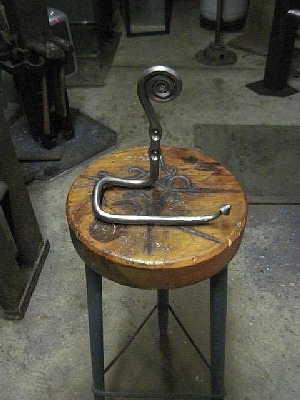
BP0819 TP Holder
by Sam Salvati
Forged this up for my mom and Dad, from some 1/2 round. Did a wire wheel finish, with oil on that. Thought you all might like it.
http://iforgeiron.com/content/blueprints/800/819/01.jpg
http://iforgeiron.com/content/blueprints/800/819/02.jpg
http://iforgeiron.com/content/blueprints/800/819/03.jpg
http://iforgeiron.com/content/blueprints/800/819/04.jpg
Images Copyright Sam Salvati, -
IForgeIron Blueprints
Copyright 2002 - 2012 IFORGEIRON, All rights reserved.
BP0820 RR Track Plate Box
by Garey Ford
http://iforgeiron.com/content/blueprints/800/820/01.jpg
i have a anvil with the heel broken off. I needed a way to hold hardy tools so i built a box from RR track plate
http://iforgeiron.com/content/blueprints/800/820/02.jpg
4 track plates i got off of several old RR ties ( leagely)
http://iforgeiron.com/content/blueprints/800/820/04.jpg
The box welded up , mounted on a stump with spikes
http://iforgeiron.com/content/blueprints/800/820/05.jpg
2 different swedges mounted in the box
http://iforgeiron.com/content/blueprints/800/820/06.jpg
Leave the ends open and store the tools inside.
-
IForgeIron Blueprints
Copyright 2002 - 2012 IFORGEIRON, All rights reserved.
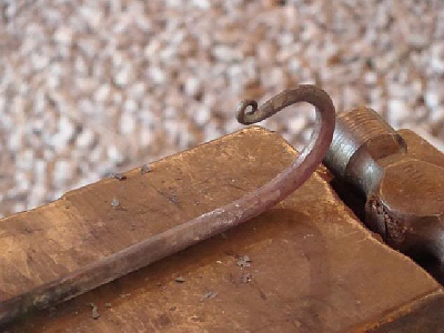
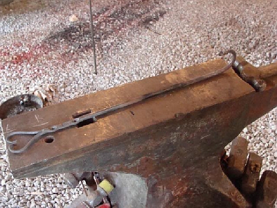
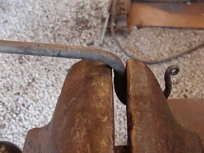
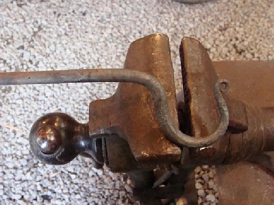
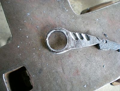
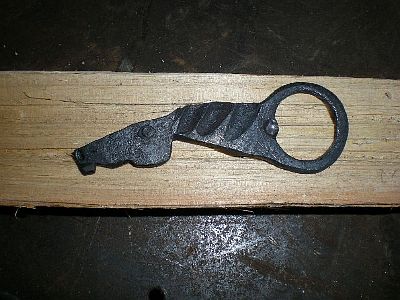
BP0830 Latch and pull
By Thomas Dean
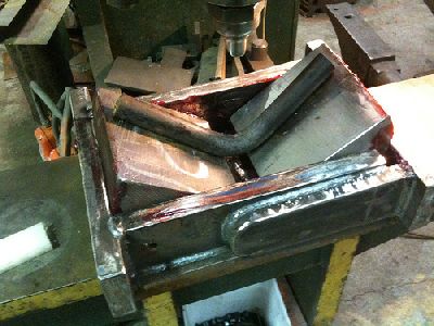
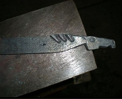
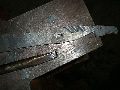
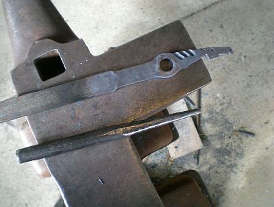
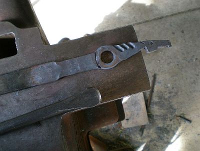
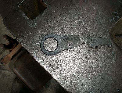
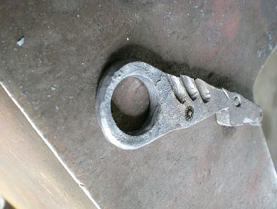
Here is the latch that I was making when it grabed my finger and resulted in the 7 stitches. It goes on the doors of a 48"dia x 48"lg cooker with an internal rotisserie for roasting corn and the like. (expensive little latch!)
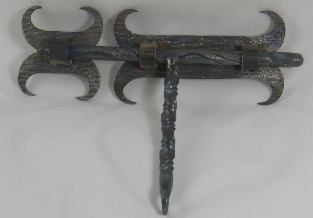
Also made the door pulls, (no body parts were harmed during the making of the door pulls)
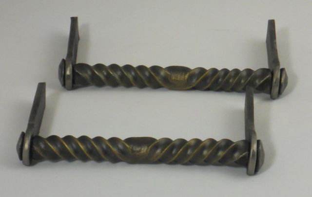
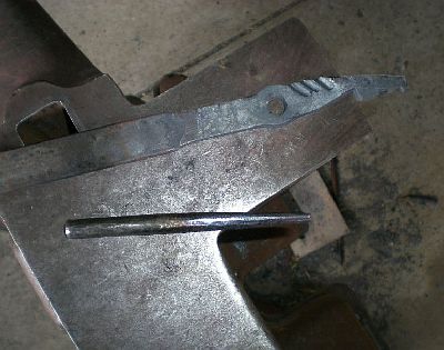
To attach I TIG welded 2ea 1/4" bolts to the backs of each, Cut the heads off so they will fit tight. The cooker is still in production, being built by my suprv. at work. When he finishes it I will post a pic or 2. Unfortunatly there was more blood the sweat on this project!
it's a barrel bolt.
Actually it is soot from the weld. Happens if there is any scale left from the forge and evidently there was some even tho I did buff it....clamped securely in the vise and using a slower buffer! I was able to get it all off with a small hand brush. From the blood still on the floor by the grinder that thing should have been RED! Once cleaned good I heated with a torch til blue and then several coats of clear varnish. -
IForgeIron Blueprints
Copyright 2002 - 2012 IFORGEIRON, All rights reserved.
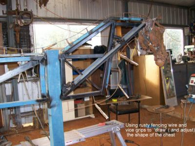
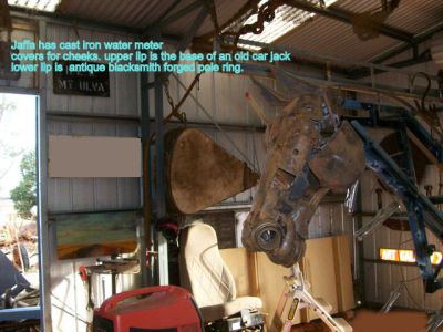
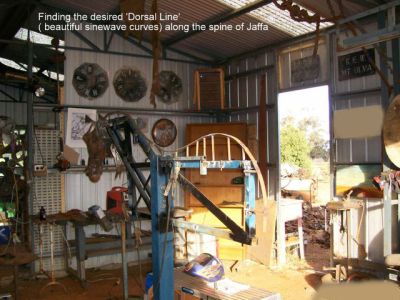
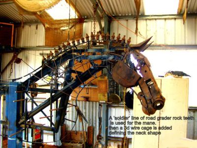
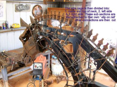
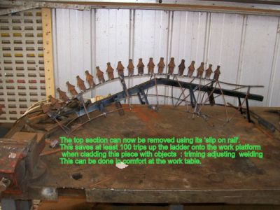
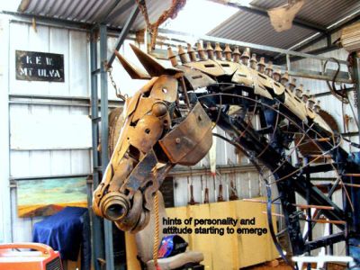
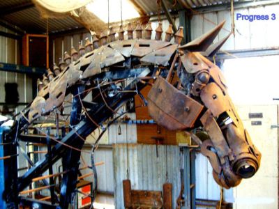
BP0830 How to build a horse
by Scrapartoz
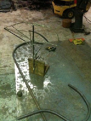
Hi folks Ive started on a memorial sculpture of a horse and rider for the parents of young girl tragically killed in a horse riding accident. The work will be inspected in October and if accepted I will commence work on the rider. The horse is Jaffa and the beautiful, talented and inspirational 16 year old girl was Taylor Farley.
Here is the record of the construction of "Taylor and Jaffa"
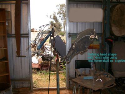
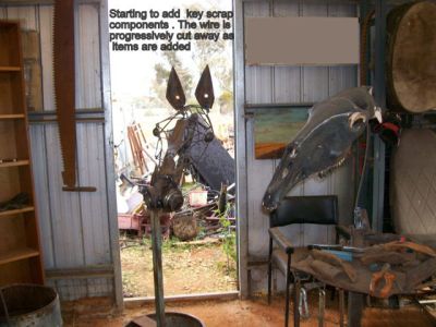
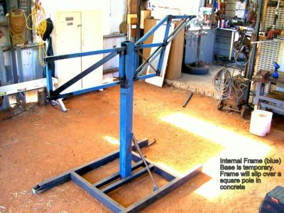
Because I do this part time it will take about 7 months to complete.so progress will seem a little slow. Thanks for the encouraging words. I will try to show the entire process so that a beginer can have a go at a big project like this.( without all the sleepless nights solving the engineering dramas)
-
added 700 last night, and 800 and 900 this morniong, plus half of the 200 and none of the 500 series have photos
If everyone can do us all a favor, I noticed while doing the 900 series that there were many duplicates there from other series. So if while browsing these you notice a copy, let me know the BP numbers of say 923 and 400 are the same so I can removed the copys.
-
IForgeIron Blueprints
Copyright 2002 - 2011 IFORGEIRON, All rights reserved
BP0701 Adjusting Multiple Legs
by Calala
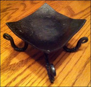
Fine adjustments can sometimes take longer than making an item, for small table top items I place a piece of glad wrap on a FLAT surface then apply a small button of clear silicone sealant to the bottom of each leg, place on glad wrap and press down lightly so as to just flatten the silicone slightly, allow to dry then remove glad wrap and you have a none slip/none scratch/level item. -
IForgeIron Blueprints
Copyright 2002 - 2007 IFORGEIRON, All rights reserved
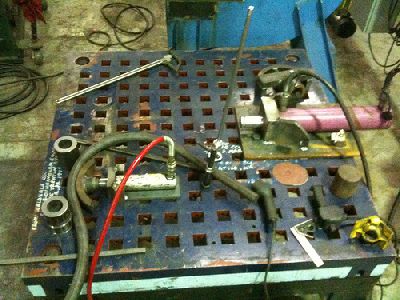
BP0702 Blacksmithing Tools
by Monster Metal
I have been doing some bending on my platen table and am in the mood to build some tooling and fixtures for it... Was hoping to get you all to share your best stuff!
This is what I have been doing.. I have a grab rail that is 1 3/8 solid, bent it all cold on the platen table The 10 ton rig just has square pegs that drop in, you can just pick it up and drop it anyplace on the table, the 30 ton rig needs to be bolted down... I have various tooling to push, V's, flats, rubber snubs and shapes....
Finished rail parts and template
Would have been a big job to do all this bar hot... but only a couple hours work cold....
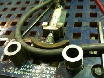
My version of the Grant Sarver half round bendy thing..
Nice bendy thingy, what size round did you use for your jig under the metal muncher?
It's 8" round x 8" long which gives a pretty good work area. I have a 10" long chunk of 16" cold rolled round. I might make a narrow one out of that chunk to use under the 200ton press. Would give an effective lower die opening of 32" which should allow a 90 deg bend in like 3.5" sq cold -
IForgeIron Blueprints
Copyright 2002 - 2011 IFORGEIRON, All rights reserved
BP0703 Anvil Bending Tool for bending a hanger bracket
By - Jeremy Knippel
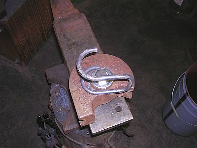
I could use the dies for my Hossfeld bender for radiused bends if I had a way to attach them to the anvil that has a 1" hardy hole - so this is what I came up with - with some misc. things laying around in the shop. This can be done using almost any die for a similar bender, and may give you ideas how to do things on your anvil. The reason for making the die for use on the anvil is so that the arms of the bender are not in the way and this allows for more freedom of use. This method can be used for any size die or such as need - this was just for the one I need at the time for multiple bends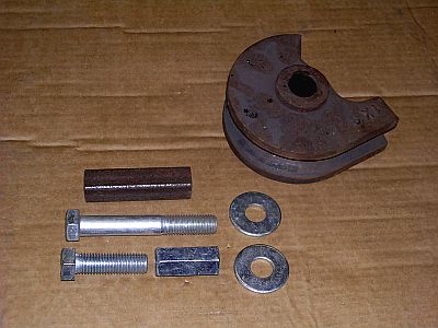
Picture 1 - Parts may need to be changed according to what dies are used as this can be modified for lots of things.
Assortment of stuff - 4-1/2" of 1" square tubing, a couple 3/4" bolts, 3/4" washers, 3/4" threaded rod coupler, and not shown is 16" of 3/8" rod.
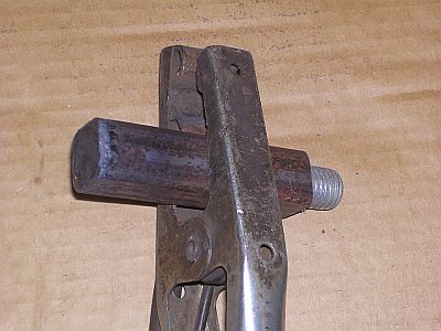
Picture 2 - Cut the head off the long bolt and insert into the tube and plug weld the end good.
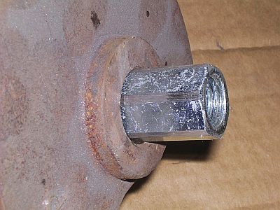
Picture 3 - The die has a 1" bore so slightly grind the hex corners off the 3/4" threaded rod coupler just so it will slide into the die bore.
Picture 4 - Weld 1 of the 3/4" washers to the end of the coupler
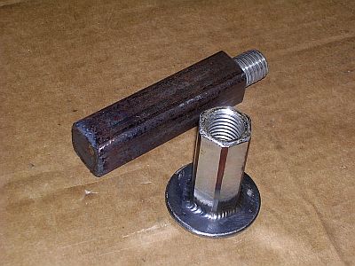
Picture 5 - Thread the washer/coupler onto the threads sticking out of the square tube.
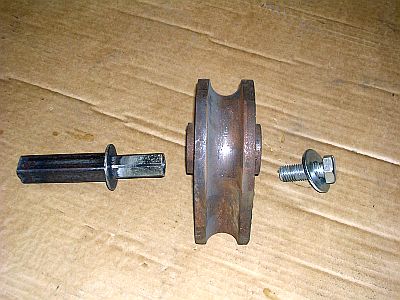
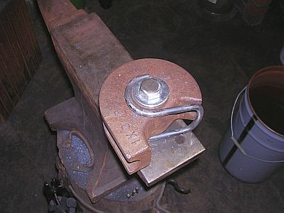
Picture 6 - Assemble hardy stem to die with an appropriate length 3/4" bolt and washer.
Picture 7 - Slide hardy stem into hardy hole on anvil.
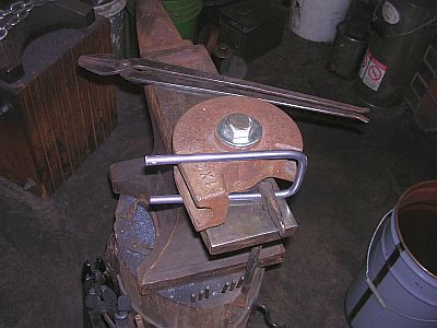
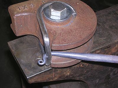
Picture 8 - Bend the 16" x 3/8" rod into a "U" shape with the distance of the "U" on the inside being the thickness of the die with a touch of clearance. In the picture, a rodded chisel that is stuck into the prichel hole just to hole the rod in place(just for the picture).
Picture 9 - Heat the end of the 3/8" rod and bend around the center die hub. When you start the bend make sure the "U" end is just inside the radius of the die, that way when in use this rod stops against the die corners. *** only bend the rod around the hub 180 degrees and cut after bend so it is half the diameter of the hub - that way you will be able to slide it on and off.
Picture 10 - Shows both ends bent and ready to slide back onto the die.
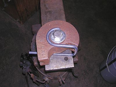
Picture 11 - Shows the rod assembly on the die and ready to work.
Picture 12 - Shows at hanger bracket ready to be made.
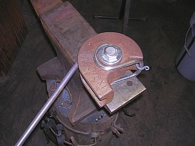
Picture 13 - Shows the hanger bent around the die to desired stopping point.
Picture 14 - Shows the completed bend on the hanger bracket.
-
IForgeIron Blueprints
Copyright 2002 - 2007 IFORGEIRON, All rights reserved
BP0704 Anvil Repair
by Robb Gunter
© Robb Gunter and Karl Schuler
The Forgery School of Blacksmithing
This process works well on wrought iron base anvils and cast iron base anvils with a good tool steel top. It was developed with the help of several metallurgists and welding engineers at Sandia National Laboratories.
Grind all surfaces to be welded. Expose good, clean material. Grind through all folds or fractured chips. Chamfer any holes or severe depressions in preparation for welding. Preheat a wrought iron base anvil to 400 degrees and a cast iron base anvil to 450 degrees. The temperature can be verified with a Tempil Stick crayon available at Your welding supply store, which melts at a given temperature. (i.e., 350 degrees, 400 degrees, 450 degrees. A propane-fired weed burner works well to preheat the anvil. A wood fire call also be used if care is taken to wire brush off all carbon and smoke deposits before welding. Be careful to not overheat the anvil, particularly the heel and hardy hole area, as it's a thin- ner cross-section and heats faster than the more massive parts.
What You'll Need
If your anvil has a wrought iron base and the damaged area goes through the tool plate so that You have to begin the repair by welding to the wrought base material, use Stoody 2110 (or equal) 3/16" rod (DC reverse works best; however, it will run AC); Unlimited passes. Expect 45 Rockwell C as welded. When you can finish building up the repair area in no more than three passes (or layers thick), use Stoody 1105 (or equal) 1/8" rod (DC reverse, or AC); expect 50 to 52 Rockwell C as welded, which should be consistent with the original hardness of the tool plate. The Stoody 1105 is a particularly good match for the W-1 tool steel tops of most anvils and is designed to be impact resistant.
When welding to a cast iron base anvil and on to the cast iron base, a layer of NI rod (high nickel) must be Put down first. Build Lip over the NI rod with Stoody 2110 (or equal); Unlimited passes (DC reverse); expect 45 Rockwell as welded. The last three passes (or layers thick), use Stoody 1105 (or equal) 1/8" rod (DC reverse); expect 50 to 52 Rockwell C as welded if you don't exceed three passes thick. Cast steel anvils repair well using the combination of the Stoody 2110 and the Stoody 1105 (last three passes).
Repair to the Horn
Repair to the horn of a wrought iron base anvil can be accomplished with 6010 welding rod as needed. If the point of the horn is blunted or slightly broken off, we usually Put the end of the horn in a coal forge, heat it to bright orange and forge it out to the desired shape using a 12-lb. sledge to back it up and a 2-lb. rounding hammer on top. Repairs to the horn of cast iron anvils is usually done by welding with the NI rod and grinding.
If the area around the hardy hole or pritchel hole needs repair, weld using the above detailed process; however, inserting a chill (or form) made of 1/16" sheet copper into the respective hole before welding will save you a lot of grinding and filing to true up the hole.
These hard surfacing rods used here to repair anvils are quite gravity sensitive during the welding process. If you can lean the anvil at 445 degrees against a cinder block while welding on the edges, you will have more of the somewhat expensive welding rod on the anvil and less on the floor.
After all welding repair is complete and you are sure that there is sufficient buildup to allow for grinding to the desired finish (check with a straightedge), post heat back to 400 degrees or verify with the Tempil Stick that the anvil is still that hot from welding. Pack the anvil in vermiculite (crushed mica), available at most nurseries, to allow it to slow cool for a minimum of eight hours. This will minimize the potential for stress cracking from welding.
Obtaining the Desired Finish
Grind the anvil to the desired finish. We start the grinding process with a 24-grit cup stone on a large body grinder It is quite aggressive at quickly removing metal. Be careful to keep it running flat (sparks coming off both sides of the cup stone). Continue the grinding process using flex back metal sanding discs, starting with 24 grit and working down to 240 grit, in five or six steps. Until now, all edges should be kept sharp and square. With 100 grit or finer sanding disc, radius the edges to your desired shapes. Near the anvil step the radii are typically ground to a 3/16" or 1/4" radius and tapering to nearly no radius at the heel of the anvil. The edge of the step and the heel are usually left rather sharp and only broken with a file. A final polish call be done with a Scotch Brite disc and you can usually see your face in the anvil top.
This anvil restoration process has been used on several hundred anvils around the country with great success.
Robb Gunter graciously provided IForgeIron permission to use this article.
Glenn -
IForgeIron Blueprints
Copyright 2002 - 2011 IFORGEIRON, All rights reserved
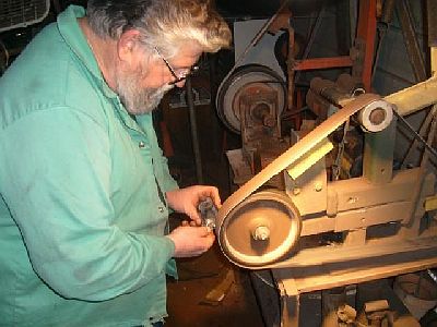
BP0705 Belt Buckles
by Garey Ford
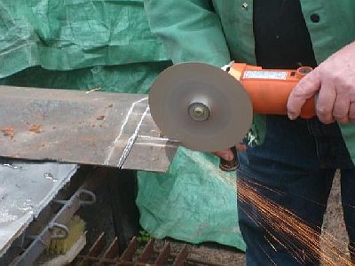
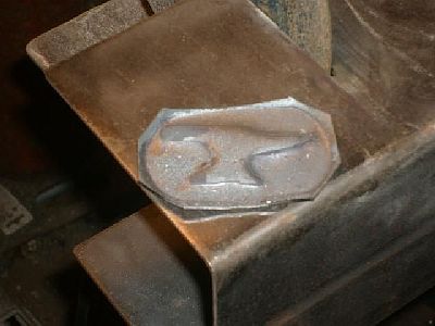
Making an anvil belt buckle. Cutting the blank from a piece of 16 gage sheet metal with a cut off disk in a side grinder. (wear eye protection! )
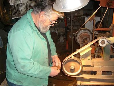
Cleaning up the sheet metal blank on the belt grinder.
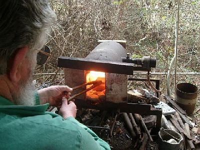
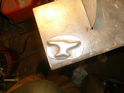
Heating the blank up in the forge.
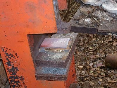
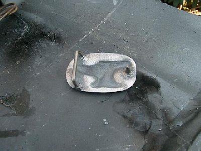
Hot blank placed on the bottom die.
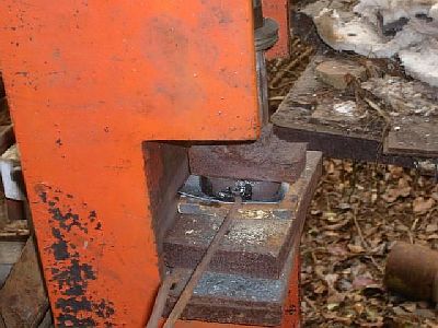
Top die and hot blank pressed into the bottom die.
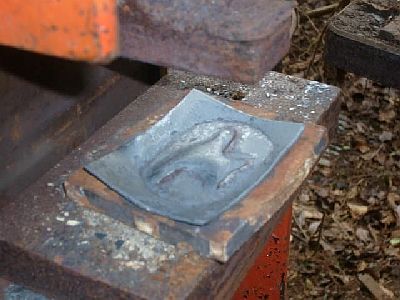
Blank pressed out.

Pressed out blank.
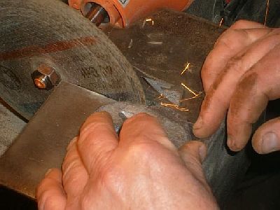
Cutting excess flashing off the blank edges.
Rough cut blank ready for sanding the edges.
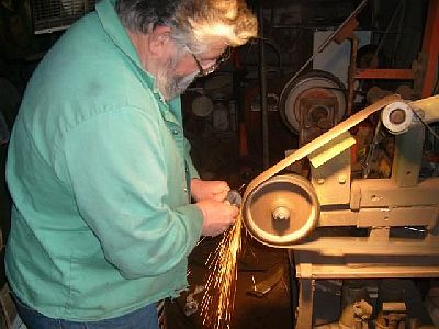
Cleaning up the edges of the blank.
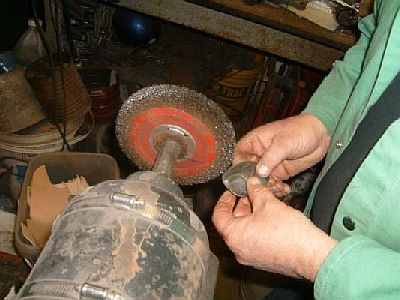
Wire brushing the blank.
Buckle blank cleaned up ready to weld the belt loop and catch stud on the back.
Cutting the heavy wire for the belt loop and the catch stud on the throatless shear.
The belt loop bent and shaped in the vice.
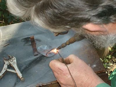
O/A welding the belt loop on the back of the buckle.
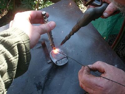
Son holding the catch stud while I O/A weld it on the back of the buckle. (some things need 3 hands.)
Wire brushing and buffing the buckle.
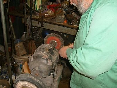
Wire brushing and buffing the buckle.
Back of finished buckle.
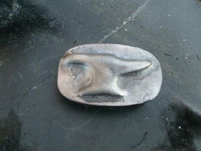
Front of finished buckle. Soak the buckle in vineger for a while to soften the black fire scale and it will brush of easy. -
IForgeIron Blueprints
Copyright 2002 - 2011 IFORGEIRON, All rights reserved
BP0706 Adjustable Bending Forks
by Dan E
Adjustable bending fork fabricated from a derelict monkey wrench. The adjustable feature is very handy when bending forged tapered work pieces, such as snakes and other organic forms. I have two sizes. The on shown is for larger work.
-
IForgeIron Blueprints
Copyright 2002 - 2011 IFORGEIRON, All rights reserved
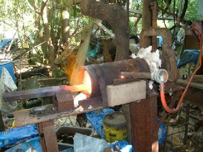
BP0707 Cable Twist Forge
by Garey Ford
This little forge is built from a Marine diesel engine cylinder sleeve.
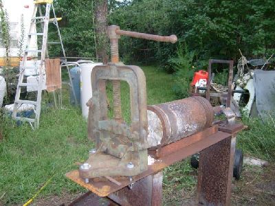
The little forge on the frame with a pipe vice mounted on one end
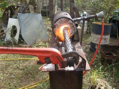
1&1/4" cable in the forge being twisted with a pipe wrench. other end is clamped in the pipe vice
Another view of the cable being twisted up
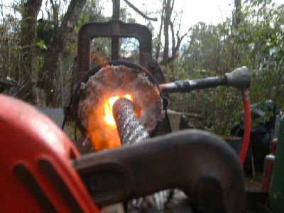
Twisting the cable . second pass through the forge to make sure it is all welded up good
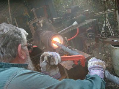
A short piece of cable with heavy wall square tubing welded on each end . a 18" crescent wrench is used to twist with on the square tubing. the pipe wrench will slip on round hot cable and hit you on the nose.
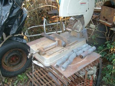
The welded cable cut into lengths for forging flat
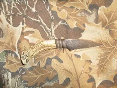
A little 4" warncliff blade made from some of the twisted cable
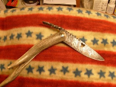
a friction folder made from a piece of the twisted cable
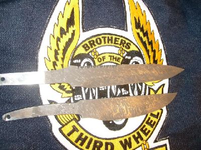
2 blades made from twisted cable .
-
IForgeIron Blueprints
Copyright 2002 - 2011 IFORGEIRON, All rights reserved
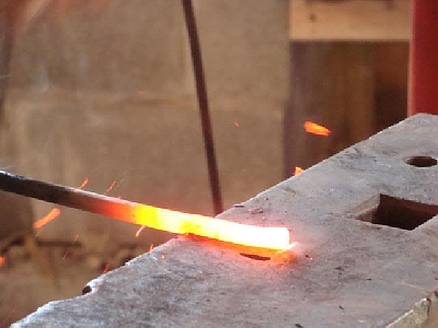
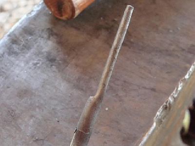
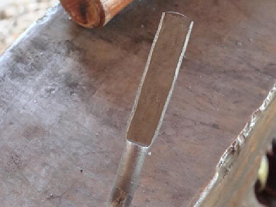
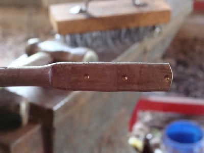
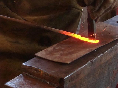
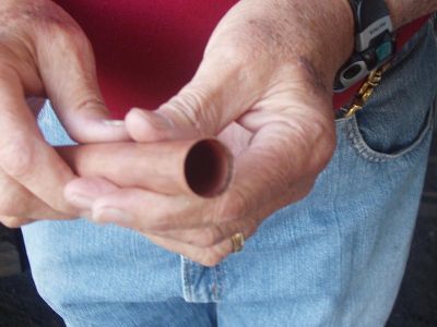
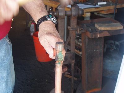
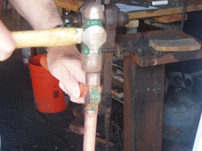
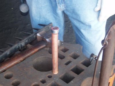
BP0708 Horse head bottle opener
by Clinton I made a couple of bottle openers yesterday and took some pictures of how I do it. I learned this from Brian Brazeal, and there are some key points to follow in order to get an opener like this.
Mark for slitting
Slit a hole Attached
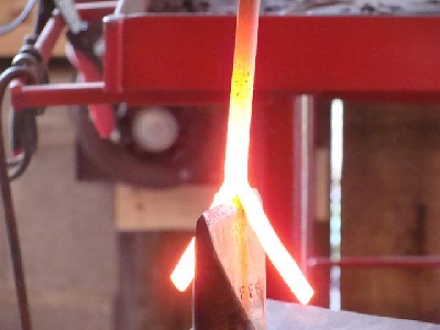
Drift to 3/8 inch
Drift to 3/4 inch
Mark for cutting
Work over the horn, chamfer edges
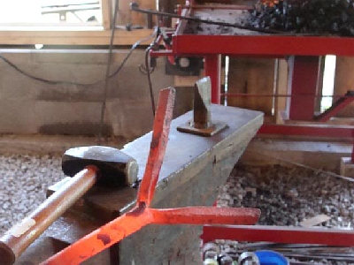
Drift too cold and split it open
Start over
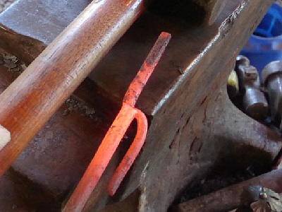
The final drift is 1 inch- no more or you will not end up with a nice round opener, you can not forge or hammer anymore even at a black heat after you drift to 1 inch, straighten it out and leave it alone. If you do end up with one that is too big thats fine you just take another heat and flatten the end, some people make them like that, I prefer the perfect round myself. -
IForgeIron Blueprints
Copyright 2002 - 2011 IFORGEIRON, All rights reserved
BP0709 Calipers
by teenylittlemetalguy
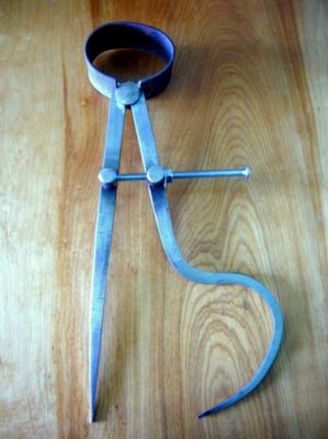
For a long time now I wanted to try building a set of calipers. I have held a fascination with them for a very long time and they seemed pretty straight forward. I could have used a set of odd leg ones on a project a while back so decided to put them on my list to get. So with this build I killed 2 birds with one stone.
Since this was really just to see if I could do it I used mild steel for all but the spring. Purchased a 4" x 1/4-20 machine screw for the adjuster. The posts were 1/2" rod. Turned a 3/8" long section down to 1/4" on the lathe to mount though the leg. A washer and then riveted the head down on the back. over did that a bit so I had to take a while loosening them up. but they work great now. Overall length is 12" as I wanted more range than a tiny set would give me.
Typically springs have been a problem for me, but I learned a lot on this build about how to make a spring and am comfortable with the strength and tension in this one.
I will build a nicer nut and case harden the tips before I put them away.
-
IForgeIron Blueprints
Copyright 2002 - 2011 IFORGEIRON, All rights reserved
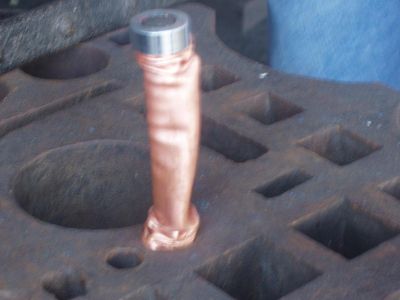
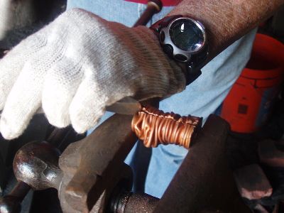
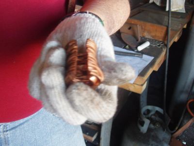
BP0710 Copper belt buckle
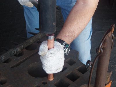
by Kohyar NaderiIn manufacturing of this belt buckle, I use 3/4" ridged copper pipe.
cut this into pieces 8" long and anneal by heating to red heat and immediately quenching in cold water. This will soften the pipe and allow it to be deformed.
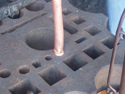
Flare out each end of the pipe by tapping a 1" ball bearing or you can use a small peen of a ball peen hammer by holding the peen on the ends of the pipe and hammering it down with another hammer. After flaring the ends of the copper pipe proceed as follows.
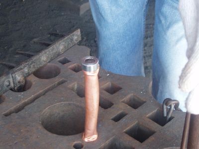
Place the pipe over a 5/8" mandrel
Put a bushing and washer on top and a washer on the bottom.
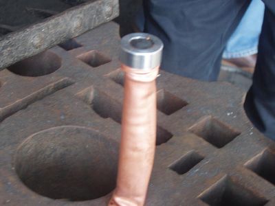
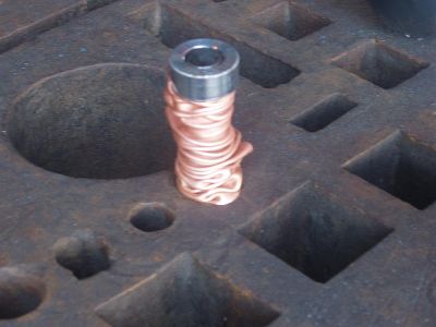
Hammer the mandrel over an anvil or other stationary plate until the pipe collapses to 2" high turning pipe quarter way after every hammer blow.
remove the pipe from the mandrel and saw it length wise leaving the best pattern for the front.
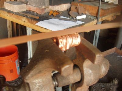
Anneal the pipe and quench then open the collapsed pipe with a chissil and other tools like a fuller.
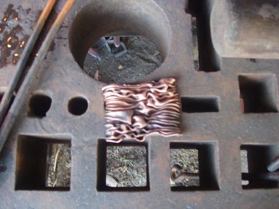
Once opened far enough that the ends will fold if flattening is attempted. Flatten with a rawhide mallet or rubber mallet using a soft black plate of wood or plastic. This is to avoid damaging the finish.
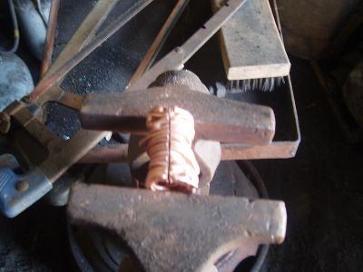
Clean edges and corners with a belt sander and anneal and quench a third time.
Using a silver solder, attack a belt loop and hook made of 8 to 10 gauge copper wire to the back of the buckle. Finishing methods: Method #1: pickle copper in sodium bisulfate/water, rinsed, then buffed with scotch brite. Be sure to wear gloves at every step following cleaning. Dip in liver of sulfur to darken the low areas then buff again. (hand pad from medium to extra fine) to polish the high areas. Seal with a clear matte spray like Krylon or Permalac. Do all soldering prior to finishing using 5% silver solder. Method #2: Polish on a cotton buffing wheel using Tripoli compound. 1140 to 1750 RPM is fast enough. Clean with Joy soap and a soft tooth brush. Apply a little heat to dry then a clear coat.
-
IForgeIron Blueprints
Copyright 2002 - 2011 IFORGEIRON, All rights reserved
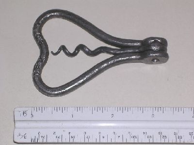
BP0711 Forged Corkscrew
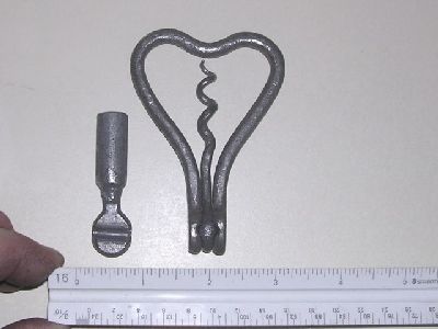
by Jeremy Knippel This is the description for making this folding corkscrew.
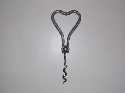
This one is 3.5" x 2.5" closed and 6" open.
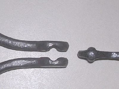
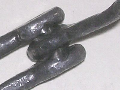
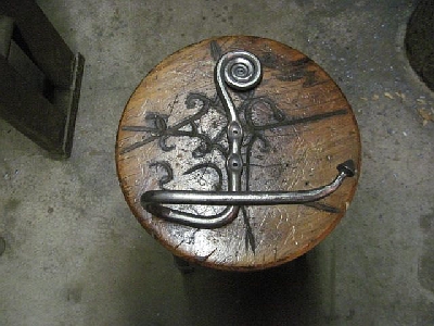
This is the process..... I started with a 5" piece of 3/8" round stock - upset each end for enough mat'l to forge a 1/2" ball on each end. The balls got flattened slightly along with a 3/16" rod on one side for the depression(pivot lock). I then forged the mat'l between the balls down to 1/4" round. I then shaped the handle and aligned the ends. Another piece of 3/8" was up set for a 1/2" ball for the center piece that has the "worm" on it. Once the ball was forged I tapered the other end for the shaping of the worm. I will drill a hole through all 3 ends for an axel rod, this keeps the pieces in place during pivoting while the handle acts as a spring to hold the position during open or closed. I didn't drill the hole for these first pictures to show that this was completely forged only up to this point.
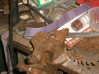
A spring swage was made like the second picture for swaging the ball for the worm. This made the ball into the shape shown with a raised groove( the lock locator) after swaging for the center part of the pivot.
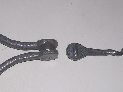
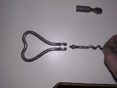
Here's the final assembled corkscrew. The middle picture is of the pivot halfway open so you can see how the handle springs apart. The 3/16" diameter axle is press fit into the center part with a tad of a larger clearance holes in the handle ends. This "snaps" into the open or closed position very possitively, although very easily opened.
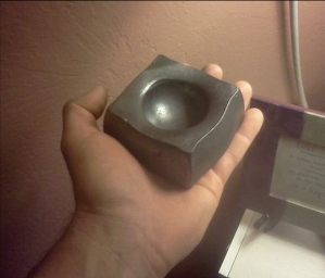
BP0811 How to flatten a cube
in BP 800 Series
Posted
IForgeIron.com Blueprints
Copyright © 2002 - 2012 IFORGEIRON.COM, All rights reserved.
BP0811 How to flatten a cube
by IForgeIron
I have been trying to flatten out a 1" cube to make a candle holder base I saw. The base has distinct corner edges and the sides are bulged out evenly. I'm using a power hammer and I just can't get it right. I'm suspecting that the base I saw may have been done with a press instead of a power hammer given my results. Anybody familiar with the proper technique?
Heat the cube, Quench the top 1/3 of the cube to black put it on the flat dies and smack a few times. Don't go to far as the top will heat back up.
If it don't look like you want play with the process. After you do a few you may get what your after. I some times I quench both the top and bottom then flatten it clear down you will have the top and bottom outline in the 2 faces.
Arean Ellis
This one was done with a power hammer. The tool used was a broken tow ball welded on to a length of steel for a handle.
IForgeIron
i'd weld a flat plate to the top of the ball ..... or you may end up with a bunch of divots on your top die in the powerhammer...
Grinding a decent sized flat area where the hammer strikes the ball works well to protect the upper die from hash marks....
Drilling a starter hole in the cube will help center the ball.