

Steve Sells
-
Posts
9,162 -
Joined
-
Last visited
Content Type
Profiles
Forums
Articles
Gallery
Downloads
Events
Posts posted by Steve Sells
-
-
IForgeIron Blueprints
Copyright 2002 - 2011 IFORGEIRON, All rights reserved
BP0404 Anti-roll Holder
by Irnsrgn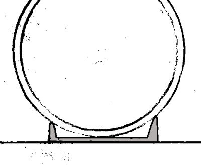
Occasionally when working on a Hydraulic Cylinder or other Round Item its hard to get it to stay in one place and keep from rolling around while its on a flat table. Short cut offs of Channel Iron make dandy remedies for this problem and you can even roll the item in them if not too heavy, such as torching saddles etc on pipe.
-
IForgeIron Blueprints
Copyright 2002 - 2007 IFORGEIRON, All rights reserved
BP0258 Plasma - explained
by Jr. Strasil, Mr. Bill.1. There are 3 states of Matter, SOLID, LIQUID AND GAS , Some say that a plasma is the 4th state of matter. 2. A PLASMA in this sense of the word is a Super Heated Gas. 3. A plasma works by super heating common air under pressure and pushing a portion of it thru a small nozzle to literally vaporize any metallic substance in its path whether it be Ferrous or Non Ferrous in nature. 4. If it says the machine uses 5 cubic foot of air a minute, this usually means that 1 cf of air comes out of the nozzle and 4 comes out around the nozzle to cool it. 5. The Plasma stream coming out the nozzle is coming out at somewhere around 200 mph and at a temperature approaching 28,000 degrees. 6. Whatever the Capacity or Thickness the machine is rated at is at a speed of 10 inches per minute. For instance if the machine says a capacity of 1 inch, It will cut 3/8 inch material very well and as the thickness increases the inches per minute of travel are greatly reduced. 7. Whatever the recommended input air pressure is, increasing it will not improve the cutting ability of the machine, but will greatly increase the slag or dross it leaves, and shorten the life of the consumable tips. 8. Plasma is usually limited to the thinner materials as it has a tendency to not cut straight thru like Oxy Acet does on thick material. If you experience a slanted cut from your plasma, you will notice that the slant is tapered to the outside bottom on the right side of the torch and slanted in at the bottom on the left side of the torch usually in the direction of travel. 9. There are 2 types of torches, those that have to make contact with the material to cut and those with a pilot that are stand off and do not make contact with the material, the later type will usually destroy a tip if contact is made with the material. 10. Don't touch the consumable tip components with your fingers as this will shorten the life of the tip from contamination by the oils on your skin. 11. Some machines have a variable power rating, this is to conserve electricity and wear on the tip consumables and to make a better cut. 12. PLASMA MACHINES LITERALLY VAPORIZE THE MATERIAL BEING CUT AND THIS MATERIAL IS FLOATING IN THE AIR AND CAN BE INHALED BY YOU AS YOU WORK, WEAR A MASK OR RESPERATOR DESIGNED TO FILTER THIS MATERIAL. 13. Commercial business's that use Plasma on a day to day basis a lot, will have water tables (A cutting table with water just below or covering the material being cut) to keep this contamination from entering or dispersing into the air you breath. 14. TIP - Contact type nozzles or tips do not work very well with painted or rusty material, but this may be overcome on straight cuts by using a piece of flat iron as a guide and making sure it is grounded, pull the torch along the flat iron making sure the tip is in contact with the flat iron, the torch will then perform almost as well as one with a pilot or high frequency option. 15. EYE PROTECTION IS ALSO A MUST AS THE PLASMA STREAM IS BASICALLY NO DIFFERENT THAN THE ARC PRODUCED BY A WELDER. 16. TIP - on contact type nozzles, a light coating of MIG Tip Dip applied by your finger on the contact surface will prolong tip life and also keep dross from sticking to the tip as well as increasing the ability for it to slide along on the material to reduce friction. 17. TIP - Most of you will have a water trap on your air lines, and again at the plasma machine. Oil in the air line is the biggest reason for tip failure or wear out there is. There are special oil filters that use what looks like brown course toilet paper as a filter, and these are the most efficient and sure way of filtering oil from you entering your plasma system, Water traps will not filter out oil. _________________ Irnsrgn
Lots of people are getting plasma cutters for their shops and it seems they are a mystery to some. So I thought I would explain them as they were explained to me. This may clarify things or not. If I make any mistakes please feel free to correct them.
By Mr. Bill
Modern industry depends on the manipulation of heavy metal and alloys: We need metals to build the tools and transportation necessary for day-to-day business. For example, we build cranes, cars, skyscrapers, robots, suspension bridges out of precisely formed metal components. The reason is simple: Metals are extremely strong and durable, so they're the logical choice for most things that need to be especially big, especially sturdy, or both.
The funny thing is that metal's strength is also a weakness: Because metal is so good at resisting damage, it's very difficult to manipulate and form into specialized pieces. So how do people precisely cut and manipulate the metals needed to build something as large and as strong as an airplane wing? In most cases, the answer is the plasma cutter. It may sound like something out of a sci-fi novel, but the plasma cutter is actually a common tool that has been around since World War II.
Conceptually, a plasma cutter is extremely simple. It gets the job done by harnessing one of the most prevalent states of matter in the visible universe. In this article, we'll cut through the mystery surrounding the plasma cutter and see how one of the most fascinating tools has shaped the world around us.
Where Saws Failed
In World War II, U.S. factories were cranking out armor, ordnance, and aircraft almost five times faster than the Axis powers. This was largely thanks to private industry's tremendous innovations in the field of mass production.
One area of innovation rose out of the need to cut and join aircraft parts more efficiently. Many factories working on military aircraft adopted a new method of welding that involved the use of an inert gas fed through an electric arc. The breakthrough discovery was that charging the gas with an electric current formed a barrier around the weld, which protected it from oxidation. This new method made for much cleaner lines at the joints and much sturdier construction.
In the early 1960s, engineers made a new discovery. They figured out that they could boost temperatures by speeding up the flow of gas and shrinking the release hole. The new system could reach higher temperatures than any other commercial welder. In fact, at these high temperatures, the tool no longer acted as a welder. Instead, it worked like a saw, cutting through tough metals like a hot knife through butter.
This introduction of the plasma arc revolutionized the speed, accuracy and types of cuts manufacturers could make in all types of metals. In the next section, we'll examine the science behind this system.
States of Matter
A plasma cutter can pass through metals with little or no resistance thanks to the unique properties of plasma. So what is plasma?
There are four states of matter in the world. Most things we deal with in our daily lives are in the form of solids, liquids, or gases. These states are divided based on the way that molecules behave within each one. Take water as an example:
As a solid, water takes the form of ice. Ice is made up of neutrally charged atoms arranged in a hexagonal pattern that forms a solid. Because the molecules stay fairly still relative to each other, they form a solid -- something that holds its shape.
As a liquid, water takes its drinkable form. The molecules are still bound to each other, but they move relative to each other at slow speeds. The liquid has a fixed volume, but no constant shape. It changes shape to fit whatever container you put it in.
As a gas, water takes the form of steam. In steam, molecules move around at high speeds, independently of each other. Because the molecules are not bound to each other, a gas has no fixed shape or fixed volume.
The amount of heat (which translates to the amount of energy) applied to water molecules determines their behavior and therefore their state. Simply put, more heat (more energy) excites molecules to the point that they break free of bonds that bind them together. With minimal heat, the molecules are tightly bound, and you get a solid. With more heat, the molecules escape the rigid bonds, and you get a liquid. With even more heat, the molecules escape the loose bonds, and you get a gas.
So what happens if you were to heat gas even more? This brings us to the fourth state: plasma.
What is Plasma?
If you boost a gas to extremely high temperatures, you get plasma. The energy begins to break apart the gas molecules, and the atoms begin to split. Normal atoms are made up of protons and neutrons in the nucleus, surrounded by a cloud of electrons. In plasma, the electrons separate from the nucleus. Once the energy of heat releases the electrons from the atom, the electrons begin to move around quickly. The electrons are negatively charged, and they leave behind their positively charged nuclei. These positively charged nuclei are known as ions.
When the fast-moving electrons collide with other electrons and ions, they release vast amounts of energy. This energy is what gives plasma its unique status and unbelievable cutting power.
Inside a Plasma Cutter
Plasma cutters come in all shapes and sizes. There are monstrous plasma cutters that use robotic arms to make precise incisions. There are also compact, handheld units that you might find in a handyman's shop. Regardless of size, all plasma cutters function on the same principle and are constructed around roughly the same design.
Plasma cutters work by sending a pressurized gas, such as nitrogen, argon, or oxygen, through a small channel. In the center of this channel, you'll find a negatively charged electrode. When you apply power to the negative electrode, and you touch the tip of the nozzle to the metal, the connection creates a circuit. A powerful spark is generated between the electrode and the metal. As the inert gas passes through the channel, the spark heats the gas until it reaches the fourth state of matter. This reaction creates a stream of directed plasma, approximately 30,000 F (16,649 C) and moving at 20,000 feet per second (6,096 am/sec), that reduces metal to molten slag.
The plasma itself conducts electrical current. The cycle of creating the arc is continuous as long as power is supplied to the electrode and the plasma stays in contact with the metal that is being cut. In order to ensure this contact, protect the cut from oxidation and regulate the unpredictable nature of plasma, the cutter nozzle has a second set of channels. These channels release a constant flow of shielding gas around the cutting area. The pressure of this gas flow effectively controls the radius of the plasma beam.
Plasma on the Job
Plasma cutters are now a staple of industry. They are used largely in custom auto shops as well as by car manufacturers to customize and create chassis and frames. Construction companies use plasma cutters in large-scale projects to cut and fabricate huge beams or metal-sheet goods. Locksmiths use plasma cutters to bore into safes and vaults when customers have been locked out.
Plasma Art
In the past, plasma cutters were prohibitively expensive and were used primarily for huge metal-cutting jobs. In recent years, the cost and size of plasma cutters have dropped considerably, making them available for more personal projects. Artists and metal workers use handheld cutters to create unique works of art that would never be possible with conventional metal-working tools. This single tool gives artists the ability to bevel cuts, bore precise holes and cut in just about any way they can conceive.
The plasma cutter is one of the most interesting and powerful tools developed in the 20th century. Using basic principles of physics to harness the fourth state of matter, the plasma cutter performs with nearly magical results. One can only imagine, as our understanding of plasma grows, how many more tools and applications will utilize this fascinating force of nature.
credit: http://howstuffworks.com -
IForgeIron Blueprints
Copyright 2002 - 2007 IFORGEIRON, All rights reserved
BP0270 Chimney Sweep
by Jens Butler aka Oakwood
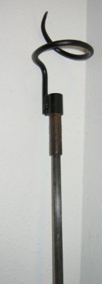
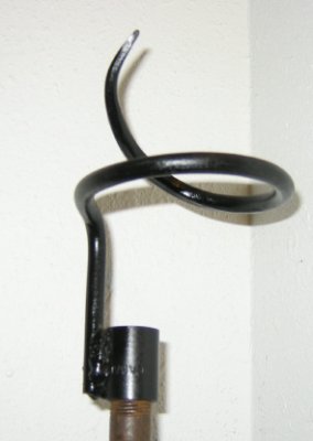
My father has a little problem with birds nesting in his chimney, the first time he went to light a fire this fall, he got smoked out. So here is my solution to remove the nests. Most Chimneysweeps should have at least one tool like this; it screws on to the end of their brush extensions. This guys brush extensions happen to have 3/8 inch pipe thread on them.
 .
.
 .
. 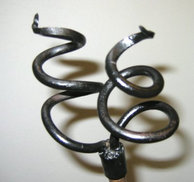
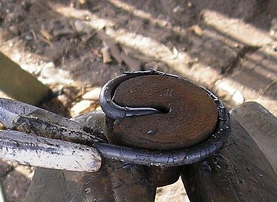
These are made by pointing a piece of 5/16 inch rod and coiling it around the horn of the anvil, simply weld to a 3/8 inch black-iron pipe coupler. Works real slick for removing tightly packed bird nests from stove pipes or chimneys. -
IForgeIron Blueprints
Copyright 2002 - 2007 IFORGEIRON, All rights reserved
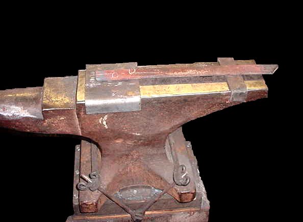
BP0271 Anvil Cutting Plate
by Jr. Strasil
When making a cutting plate for your anvil, make a narrow one for the heel, it will make it a lot easier if the piece sets flat on the cutting plate.
-
IForgeIron Blueprints
Copyright 2002 - 2007 IFORGEIRON, All rights reserved
BP0256 Blacksmithing History and Mythology
by Jr. Strasil
When doing a demo you can keep from loosing the crowds interest while waiting for a piece to heat in the forge by giving a little history of Blacksmithing. This will keep the crowd interested and also tell them that you do know a little something about Blacksmithing
Who was Hephaestus -( Hi-fest-us )? Hephaestus was the son of Zues, the king of gods, and Hera. He was born deformed and thrown out of heaven by his mother, and broke his leg in the fall, thus he was deformed and crippled. He was the God of Fire and the worker in all metals and other crafts. He is known as the father of all Blacksmiths in Greek and Roman Mythology. The Romans overthrew the Greeks, but retained their mythical gods, but changed their names. Zeus became Jupiter and Hera became Juno, for whom our month of June is named, Hephaestus became Vulcan. His shop or forge was under a Volcanic mountain where he used hot liquid lava to heat his metal. He was able to make things that were articulate and could move on their own. He made 3 golden hand maidens that helped him in the shop with his work. One day while he was eating, the mischievous handmaidens slit his apron up the middle with a pair of shears. This is the mythical story of why a Blacksmith wears a split apron. He also had a Cyclops, a mythical one eyed giant, who was his helper and striker.
The myth behind the luck of the horseshoe.
DUNSTAN the patron saint of Blacksmiths was in his shop one day, when the DEVIL came in to have new shoes put on. Dunstan recognized him as the devil, because of his cloven hooves, and grabbed his nose with a pair of red hot tongs and tied him to a post and removed the old shoes and put on new shoes. He made this such a painful experience that the DEVIL stated that he would never again go anywhere near a horseshoe again. A HORSESHOE should always be fastened with the open side up to hold the luck in, except over a Blacksmith Shop it should have the open side down, so that the luck pour's forth into the forge.
Our word MYSTERY comes from the old English word MYSTERIE which meant a trade or craft, because the guilds, similar to our present day unions, kept the workings of the trade a secret from the common people to keep them from learning how it was done. Thus it was something unknown, so it was a mystery.
To the superstitious people of olden times the Blacksmith Shop and its contents held MYTHICAL MAGICAL POWERS. The old Smiths would always strike their Anvils three times upon entering their shops in the morning and when leaving at night. This was supposed to keep any evil spirits from the shop. With the modern technology that we carry in our heads and use everyday, if we were to go back to those times we would have a very good chance of being put to death as witches. In the days of old, a sick child would often be brought to the Blacksmiths Anvil where it would be laid on the Anvil and the Anvil struck 3 times by the Smith to drive out any evil spirits. If a child was really sick it was placed on the Anvil and some water from the Blacksmith's tub was poured on the child and then 3 Smiths with the same name would pass their hammers over the child to drive out evil spirits. These practices had a mystical beginning much as round barns have no corner for the devil or evil spirits to hide in.
Blacksmithing has been a trade for 3000 years since 1000 BC, the beginning of the IRON AGE. But working IRON has been known for 6000 years, although irons was very scarce before 1000 BC.
Our own American Indians were quick to see the advantages of Iron and many of the first Treaties with the Indians required that a Smith and Smithy be set up among them.
Blacksmithing was considered the KING of TRADES many years ago because all the other trades depended on him to make their tools and accessories while he need not depend on them. Because of the lack of skilled people in other trades on the frontier he diversified his trade by taking the on the work of other trades such as the FARRIER or horseshoer, the WAINWRIGHT or wagon maker, the WHEELWRIGHT or wheel maker, the COACKMAKER, and the FOUNDER or caster of metals. When AUTOMOBILES came along he was the MECHANIC because he knew about things mechanical. In some cultures he was even empowered to perform marriages.
KING SOLOMONS TEMPLE - In the building of King Solomon's Temple, "There was not heard the sound of axe, hammer, or any tool of Iron." This applied to the actual construction and not the preparation of materials. King Solomon's iron mines were located at the north end of the Dead Sea. In Chronicles 2, we find that King Solomon requested HIRAM of TYRE to send him a 'Skillful man,' one who was capable of working in Iron. Upon completion of the Temple, King Solomon gave a huge banquet to which he invited all the overseers, or superintendents. He further ordained that the individual that had performed the greatest service toward the erection of that edifice should be honored with a seat at his right hand. There was considerable speculation as to who should occupy this favored place. The Superintendent in charge of erection pointed out that the building was perfect, therefore he was entitled to the place of honor. The Quarry-master told how he had dug out the rough stones, shaped them to specifications. Therefore, he should be favored. The head Lumberman told how he had cut the trees, trimmed and hewed them and bound them into rafts. Therefore he was entitled. The day of the feast arrived. As the many guests entered the banquet hall they discovered a Blacksmith sitting in the favored chair. When King Solomon asked by what right he expected to occupy that place, the Blacksmith pointed out that it was he who made the tools for digging out the rough stones from the quarry, he who made the chisels for shaping them to specifications, he who made the axes and other tools used in the forest and the chains to bind the rafts. His plea was so eloquent that King Solomon accorded the Blacksmith the chair at his right hand.
ALEXANDER THE GREAT - When Alexander the Great was on his journey to conquer the world, his scouts brought back word that a certain city had acquired fame in its ability to forge better swords and spears, etc. Their account was so glowing that Alexander detoured his armies 60 miles to capture the city. Mounting the steps of the city hall, Old Alex made a speech informing them that he did not want maidens or slaves, gold or jewels, but they had some iron and men who understood how to forge it. He ordered them to deliver 8 tons of iron and 9 Blacksmiths, otherwise the city would be destroyed. And they complied.
ROME- Rome had one of the worlds greatest Blacksmith Organizations without which she could not have equipped her armies. History states that at one time the hordes came pouring though the Brenner Pass bent on capturing Rome. They were met on the Plains outside Florence, Italy, by Blacksmiths, with the products of their forges, and were so decisively beaten that they fled back in disorder. The Romans are given credit with inventing the Horseshoe and the Claw hammer.
You might be surprised to know that one of the earliest industries started in the western world was Blacksmithing. You might be further surprised to know that forged Iron Bars were exported from our shores before the Pilgrims landed at Plymouth Rock. Presumably by the Norsemen, the Vikings.
The First Blacksmith in English America, James Read, arrived with the original group of settlers in Jamestown, Virginia on May 13, 1607. In the Southwest the Spanish Priests brought Blacksmithing to the New World and had a thriving Blacksmithing Industry going using Indians taught by Priests prior to 1607.
The phrase MACHINE SHOP, was first used to give an explanation of a more or less modern Blacksmith Shop. As powered tools became available to the blacksmith, he found out that these MACHINES that were also TOOLS, made his life much easier, his work more precise and easier to do, and also kept him competitive with or gave him an edge over his competition. He was using a shop full of machines, thus the name MACHINE SHOP. Today a MACHINE SHOP usually denotes a shop custom machining using Lathes, Mills, Drills, and other Precision Machines. Modern Machinists almost have heart failure if you mention that the machines they use were originally invented by Blacksmiths, but in fact a lot of them were invented or altered by Blacksmiths to due a specific job or to improve there capabilities.
UNITED STATES OF AMERICA - One of direct reasons we are a United States of America today is the fact that we had an outstanding Blacksmith industry during the Revolutionary War. Washington suffered reverses and went into winter quarters at Valley Forge. What an intriguing name to Blacksmiths--Valley Forge--the valley of the Forges. In this Valley were numerous Blacksmith Shops making guns and cannon. Some of these cannon were so ingeniously made that when the British captured them they were sent back to England for study by the military and now repose in British Museums. When those Blacksmiths in Valley Forge had made enough armament, Washington was able to resume his campaign to a successful conclusion.
ELI WHITNEY Blacksmith - Eli Whitney, got his name in the history books for inventing the cotton gin. He accomplished much more when he conceived the idea of making duplicate parts. He made 10 muskets with every part identical, took them to Washington, disassembled them, mixed up the parts, then reassembled 10 working muskets. He was given a contract for 10,000 muskets which were used in the war of 1812. To accomplish this feat he is given credit with inventing the first practical Milling Machine, which was not changed for quite a few years.
Some things you may be asked.
Cherry red heat is approximately 1420 degrees F.
Orange heat is approximately 1850 degrees F
Yellow heat is approximately 2050 degrees F.
White heat is approximately 2450 degrees F.
Pure iron melts at approximately 2750 degrees F.
Depending on the type of coal and the amount of air, a forge can reach over 3000 degrees F.
Definition of the word blacksmith: Iron is known as the black metal, Smith means the artisan or craftsman who smites or hits the metal.
If someone in the crowd says that their relative of someone they know was a blacksmith, tell them you would like to have met them, you might have leaded something from them. This will please the crowd and make you look good. If an old smith shows up and says he was a blacksmith, wipe your hand off a little and offer to shake hands with this individual. Tell this person that if they have any suggestions about how you are doing something to speak up. This will endear you to the crown and you may learn something besides. Don't under any circumstances make the crowd mad at you. Treat them with respect and you will get respect in return. If you make a mistake, own up to it. don't try to hide it. Keep your eyes on the children and teenagers. They were usually not taught to ask before handling, and can injure themselves very quickly and you will be at fault in the eyes of the crowd.
If you don't know the answer to a question, say so, don't try to fool the crowd by making something up. Someone in the crowd will invariably know the answer and you will end up with your foot in your mouth. You will also make yourself look bad and this will reflect on other smiths as well.
-
IForgeIron Blueprints
Copyright 2002 - 2007 IFORGEIRON, All rights reserved
BP0278 Simple Foot for a Flag Stand
by Bob Elliot, Glenn Conner
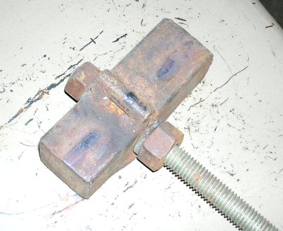
This is a piece is 1/1/2 inch square bar with a piece of 1/2 inch round welded at the middle of the block. A piece of all thread rod was available and used, but anything can be used as a handle.
Make the flag holder as usual. For the piece that sticks into the ground or foot, point one end of the stock.

You simply lay the hot end of the flag stand on the swage block, put the footing tool on top and whack it with a hammer forming the foot.
This simple foot saves you the material and effort of making a foot stand for the flag holder. It still can be punched into the ground and the simple foot will keep it in place and keep it from tuning or rotating in the wind.
-
IForgeIron Blueprints
Copyright 2002 - 2007 IFORGEIRON, All rights reserved
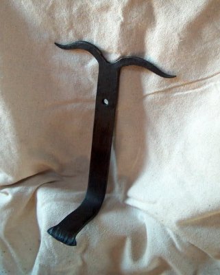
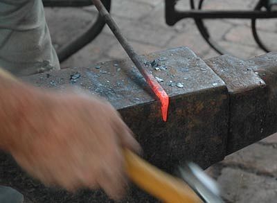
BP0292 Hat Hook
by Gerald Franklin
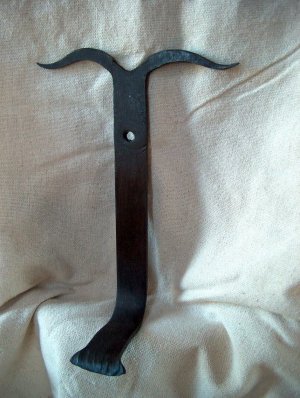
This little hook is designed to hang wide brimmed western hats but could be used for coats and jackets or even a medium sized Poodle. It makes a good demo piece because it goes quickly and incorporates several different smithing operations.
Start with a length of flat strap 12” long. This one happens to be 3/16” X 1” but almost any size will work. Center punch two marks at 1 ½” and 3 ½” from one end. The hole closest to the end will form the beginning of a split. The one at 3 ½” is to hang the hook from.

If you use a square or hexagonal center punch, your mark will be easier to find in the scale raised on hot metal.
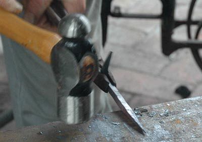
Draw the end to a taper starting at the mark that is 1 ½” from the end. Keep the taper even from side to side. Leave the point of the taper sort of blunt, as you will split it later.
Punch ¼” holes at each center punch mark.
Beginning at the hole closest to the end of the piece split the taper evenly with a hot cut. You could do this with a hacksaw, but the hot cut operation is more interesting at a public demo.

Once you have completed the split, separate the branches and draw them out into longer tapers.

Then form the tapers into longhorns over the horn of the anvil. We used longhorns in this example but a later photo will show some different ideas for forming the split ends.
Once you are finished with the horns, use the peen to draw out a fishtail scroll end on the other end of the piece.
Bend the end of the fishtail over the far edge of the anvil to give it a smooth curve. This is where the hat will hang. It needs to be wide and smooth so it doesn't punch a hole in that $700 Stetson that you will hang on it.
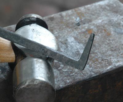
Beginning about 2 ½” from the fishtail, form a rough “L” shaped hook.
This should result in a bend that is a little less than 90 degrees. If the iron is bent at a good heat, you will naturally get a little curve in the “tongue” of the hook. This holds the brim of the hat better than if it were perfectly straight.
After a coating of your favorite wax finish, you have a quick little sale item. A hand-forged nail to hang the hook with adds a nice touch.
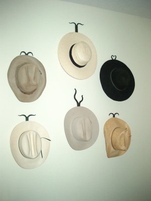
Different treatments of the split end adds variety. (Hearts, longhorns, Hereford horns, handlebar, etc).
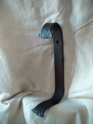
If you are really pressed for time at a demo, put a fishtail scroll at each end. It cuts out one of the hole punches, and the splitting and drawing out of the horns.
-
IForgeIron Blueprints
Copyright 2002 - 2007 IFORGEIRON, All rights reserved
BP0293 Shop Math Made Easy
Finding the Center of a Circle or Arch
by Rick of RicksironworksDon't understand algebra" Geometry not in your vocabulary? Running out of soapstone on figuring? No problem. Here is a simple method to find the center of a circle or arch, which makes it easy for anyone.
Start with a circle or arch (part of a circle).
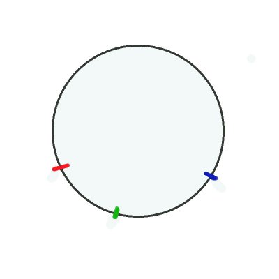
Make marks on the circle or arch in 3 different places, no need to measure. In fact, there is no measuring involved.
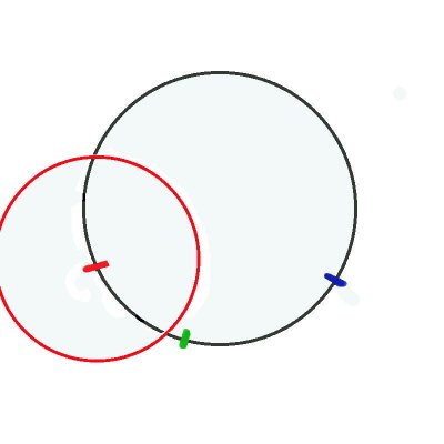
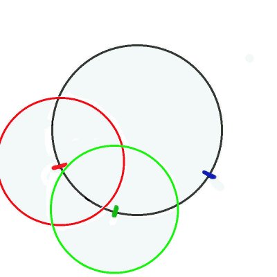
We set a compass to some undetermined amount. Put the point of the compass on each of the marks and draw a circle.
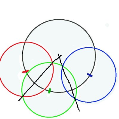
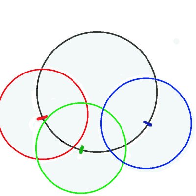
Draw a line connecting the intersections of the red - green circles, and another line connecting the intersections of the green - blue lines. Where the two lines cross is the center of the circle.
-
IForgeIron Blueprints
Copyright 2002 - 2007 IFORGEIRON, All rights reserved
BP0294 Go or No Go Gauge
by Jr. Strasil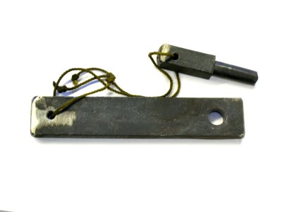
When you make a Go-No go Gauge, mark the size on the gauge and attach hole and the tenon together. This way you will have not only the size of the tool but also both pieces when you need them.
-
IForgeIron Blueprints
Copyright 2002 - 2007 IFORGEIRON, All rights reserved
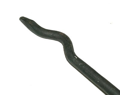
BP0295 Nail in hooks
by Strine
Photos by RachelThere has been an influx of hooks among the blueprints and not wanting to be left out I make my humble offering. It’s just a Nail-in-Hook and takes just about as long as an onlooker can be bothered on looking. Thanks that fella who came up with the original design. And thanks ‘Siss’, aka Rachel, my daughter for looking after the photography.

This is really starting from the beginning. I’m using a length of 3/8 rod for this project and the first task is to cut off the daggy end that was left over from the last job. The rod is driven almost through onto the hardy. Be careful here as your hardy will probably leave a nice scar across your hammer if you go too far.
The last little bit will virtually fall off but because it was still a bit hot it took some extra wiggling. As an aside let me say that rules, especially safety rules, exist for very good reasons and only when you are totally familiar with them and with the consequences should you ever temp fate. Dear beginners what is wrong here? You're right. Remove the hardy if not in use lest you subtract a knuckle from the tally God gave you.
Where possible a good idea is to use round stock if you want square and square if you want round. This gives the whole piece a forged look rather than just the bits you’ve hammered. Here I’m turning the round into square by first flattening about three inches. And what about the new Father’s Day hammer? Don’t tell Siss but I prefer the old one.
Turn 90 degrees and finish squaring up the rod.
Bend about 1 inch over the edge of the anvil. Without any assistance to hold down the part on the face of the anvil it will kick up. Just belt it down.

Here we are about three quarters of the way. Aim for a bend of about 75 degrees
With another heat, quench about three quarters of the short section then drive in into the anvil face. In this step the object is to work up a square corner. The squarer the better in the finished piece I reckon. If it is nice and square, when it is nailed in, the hook will appear to be magically attached to the wall or post. Also, if it’s square it won’t get damaged much when it’s hammered in.
Now to forging a point to nail in. Start with the work on the face and taper that dimension then…
…hook it over an edge and taper the other dimension. There is latitude in this step to get the square corner just as you like it but be careful not to go overboard and ruin it instead.
At this stage my nail-in-hooks look a bit like this.

Cut off about 3 inches from the ‘nail’

Remember we only squared up about 3 inches of the 3/8 rod. In this step square up the rest and begin to forge a fine point.
That is fine enough, we’re not making acupuncture needles.

Scroll the point by nudging it over the edge of the anvil while feeding forward. Oh…and if you want to know what “choking a hammer” is all about, this picture explains it pretty well! But it’s a matter of control and here we needed all that could be mustered. A hammer without a handle would have been even better.
Eventually you must turn the thing over and coax the scroll around by hitting straight on the end.
Take another heat and with a bending fork begin to make the hook part. It’s a good idea now to always quench out the scroll…it’s pretty fragile when confronted with a two pounder in full swing. It just cringes in fear and destroys itself. It won’t be your fault it does it on its own.
Finish off the hook over the horn. WATCH OUT FOR THAT SCROLL!

Almost done.
The twisting photos didn’t turn out, Siss says sorry Dad. I generally do the twisting with two stout pairs of tongs but the vice and shifter work just as well. This picture at least shows the result. It also shows an experiment I thought I’d try. At a black heat the hook is getting a spray with “Lanotech”. It’s just lanolin in a can. You never see a rusty shearing shed so it must work.

And this is the finished article. I think I’ll be using the Lanotech again.
Footnote: There are a few blueprints about that describe a pineapple twist. Part of making this decorative twist is to know how many twists you've made in the first step so that you can untwist it by half that number. The hook described above has a half twist ie one end has been turned 180 degrees relative to the other end. The number of diagonal lines on any face gives this info immediately. In the hook you will see two diagonal lines therefore it's a half twist....two being half of four. Had there been six diagonal lines it would have received one and a half full turns...six being one and a half times four. If you were using hex material the four in the calculation would become a six.
-
IForgeIron Blueprints
Copyright 2002 - 2007 IFORGEIRON, All rights reserved
BP0296 Pot Hanger
by Bill Epps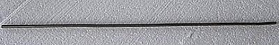
Start with 24 inches of 1/4 inch round bar.
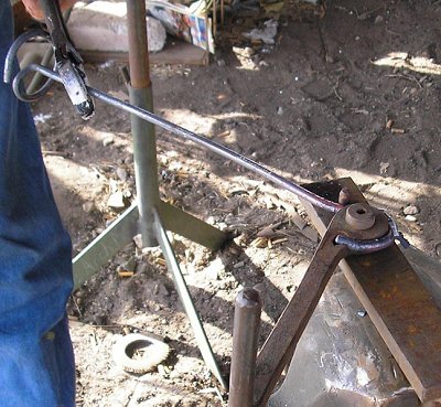
This is the tool I use to make the first bend.
Here I make a 90 degree bend. I make these up 50-100 at a time, so I went ahead and made a tool to make all of them the same.

This is the next tool that I use.

1 1/2 inch round bar with a hole drilled through the center and a groove at right angles to the hole with a slight radius at the break out point
I take a good heat, drop the shaft through the hole and bend
All the way around a full 360 degrees.
I finish off with a standard pair of Channel Lock pliers and a quench.


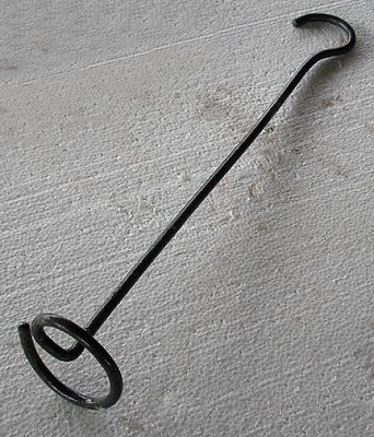
This is my hook bender that I use on the other end.
Bend the hook and bring it back to the center and quench the end.
And it looks like this.
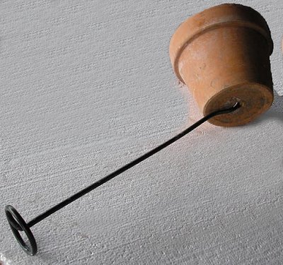
The hook end will feed up through the drain hole on any standard terra cotta flower pot.
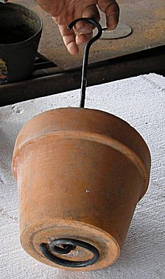
Now we have a hanging flower pot, you bed a plant in the pot and hang it up.
This is just a simple hook that sells real will at the shows that I do. They are quick and easy to make and sell for about $3.00. You should be able to make 50 to 100 of them in just a couple of hours.
-
IForgeIron Blueprints
Copyright 2002 - 2007 IFORGEIRON, All rights reserved
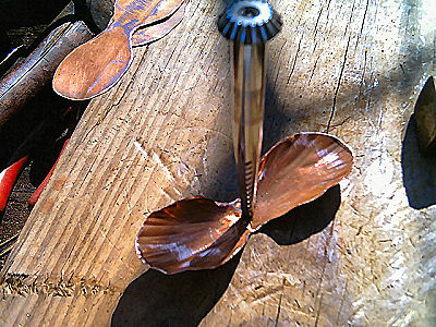
BP0297 Copper Rose
by Garey Ford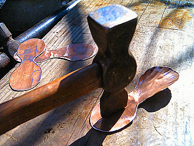
Copper sheet, leaves, templates, and tools.
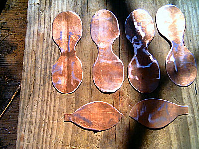
Cardboard templates, leaves and petals

Petals and leaves drawn on copper sheet
Petals and leaves cut out
Petals and leaves cleaned up.
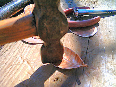
Putting veins in the leaves.
Putting more veins in the leaves.

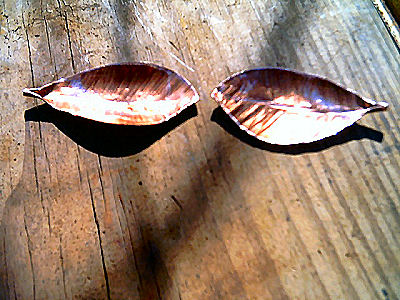
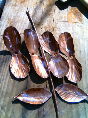
Finished leaves.
Putting texture in the petals
Punching the hole for the stem in the petals.
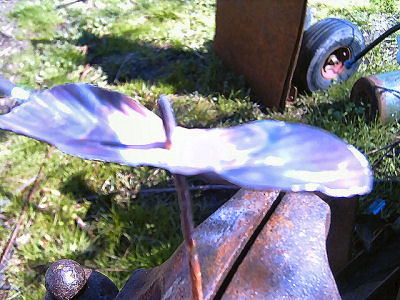
Petals textured and hole punched

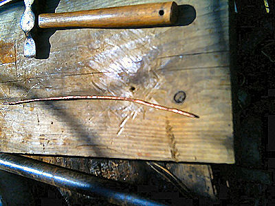
#6 copper wire textured for the stem
All the petals, leaves and the stem
First petal soldered on the stem
Setting the second petal with a piece of 1/4 pipe (is this sch 80?)
Second set of petals ready to solder

Third set of petals in position ready to solder.

All of the petals soldered in place on the stem
Centaur set of petals folded up in place.
Second set of petals folded up and shaped with the pliers

Soldering leaves on the stem
Rose all soldered together
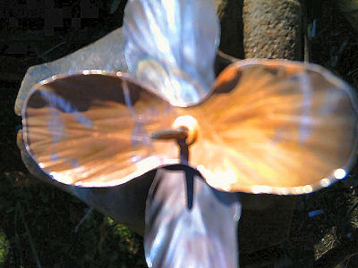
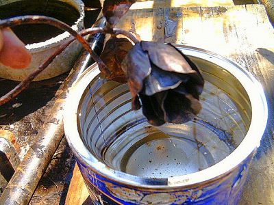
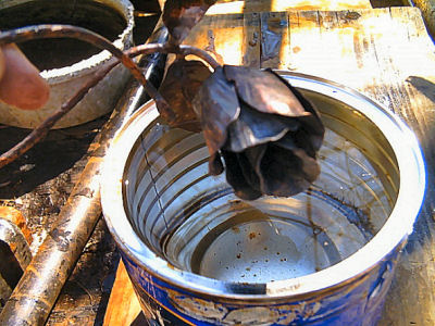
Cold water to quench the petal in after heating with the torch to get the colors.
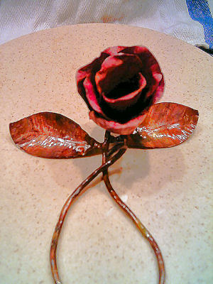
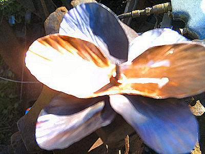
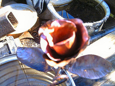
Rose all colored with the torch.
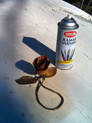
Rose ready to be sprayed with clear cote.
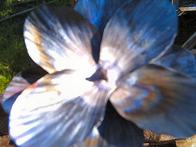
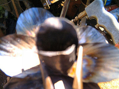
Clear coat sprayed on rose to seal it from fading.

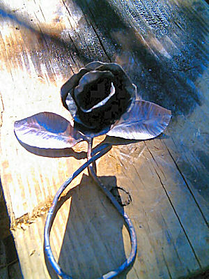
Finished rose.
-
IForgeIron Blueprints
Copyright 2002 - 2007 IFORGEIRON, All rights reserved
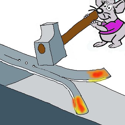
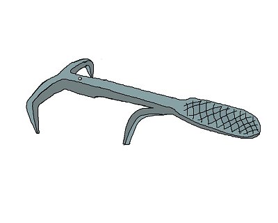
BP0299 Toaster for an Open Fire
by Duck and the Mouses

You need two pieces of stock.
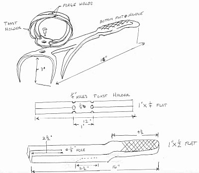
One piece is 1”x1/2” 16”long and will be used for the foot and handle. The other piece is 1”x1/4 12”long and will be used for the toast holder
Start with the12” piece, find center and mark with a punch for a 1/8 hole.

Now on each side of this hole mark holes one inch apart for ¼” holes
 .
.
Then drill your holes, the center hole is 1/8", and the two outside holes are 1/4" in diameter.

Using your center scribe mark a center line from each ¼” hole to the outside ends
 .
.
Next, using ¼” spring or guillotine fullers, fuller the sides next to the 1/4 “holes about a ¼” in deep.

and make your split
Now scarf the ends for welding.

Go back to the straps you made with the splits and over the horn round the straps together and weld the straps to make two separate loops. This gives you two rings tied together with a 1/8” hole in the middle of your tie. Flatten this so it can later be riveted to the foot and handle. While doing this go to the two ¼” holes and round the splits to the holes edges into nice curves. And shape the double rings to a circle. Moving now to the handle and foot, heat one end and round the corners.
Draw out this end into a handle shape but keep it flat and even.

The handle should now be wider and a little thinner than the rest.
 .
.
The cross hatching on the handle is next. Using a hot cutter or chisel cut diagonal lines across the handle first one way and then the other
Now take a1” bottom fuller or hardy bick and a soft hammer and round the handle to a comfortable shape. Next put an offset at the end of the crosshatching to the handle and foot. Go to the opposite end of the handle and mark from the end 2 ½”. Center scribe the 2 ½”and make a ¼” hole.
This is to be split and the two sides drawn out pointed and the center rounded to prevent shunts. They should now be about 3” long.
Now make a 1/8” hole ¾” in from the center of the T . This is where the toast holder is to be attached.

The last thing to do is making the third leg about an 1” back from the 1/8” hole make a 90 degree bend remembering that the bend and the handle both should point up. Make a split about 2 ½” long that stops close to the offset in the handle

Taper and point the split to make the third leg. Go now to the front of the handle and round the T down to make the first two legs. These three legs should be adjusted to make it stand on its own.

Finally attach the toast holder to the handle with a rivet through the 1/8” holes making sure the toast can swivel around and not burn. I usually put on a bees wax finish its food safe.
-
IForgeIron Blueprints
Copyright 2002 - 2007 IFORGEIRON, All rights reserved
BP0298 Nickel Silver Bowl
By Andrei Hand.
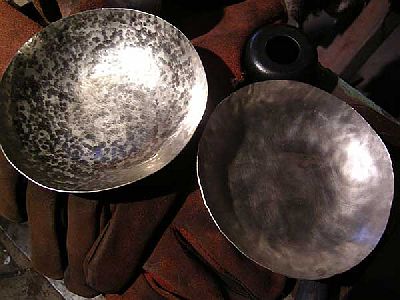
This is the way I make my bowls out of non-ferrous metals, like copper and silver. The process is called sinking, or dishing, and it involves hammering a sheet of metal into a hollow or concave form. This bowl is made out of nickel silver, and this was the first time I’ve ever used nickel. It’s a lot harder than copper and brass, which is what I normally use.

First I start by tracing a six inch circle with a compass, and cut it out with tin snips.
All of the surface’s I’ll be working on, I cover with masking tape to protect the bowl from being marked up. If you don’t cover your tools with tape, they must be mirror polished and have no sharp corners or edges that would leave marks on your metal.
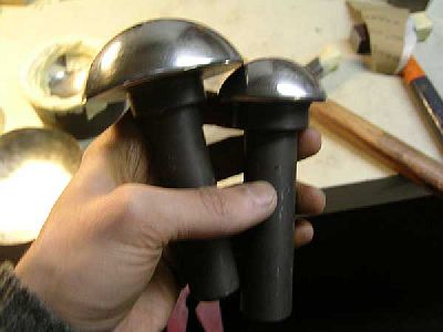
The forms I hammer into are actually dies for a hydraulic press. I don’t have the press, but the dies still work just fine. I bought them as a set, three double sided dies and six matching mushroom stakes. The big one on the left is 3 ¼’ diameter, and the smaller one is 2 ¾ diameter.
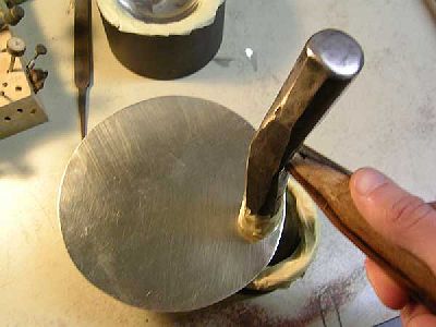
I start with the smaller die, and start hammering just around the edge. The general rule with sinking is, work from the edge into the center. I believe that’s so you don’t stretch out the bottom to much.
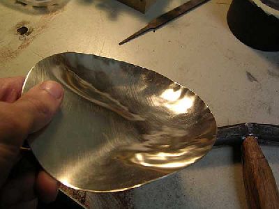
After you have worked all the way around the edge, it should look something like this.
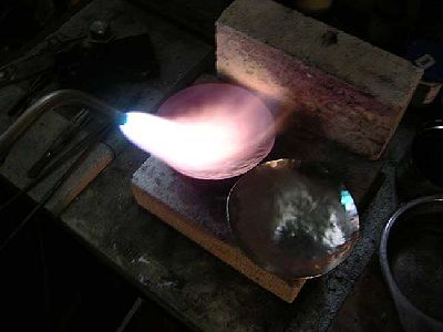
And, at this point it should be getting pretty hard, and if you try to work it further it might crack. Unlike steel, you work most non-ferrous metals wile they are cold and then anneal to soften them. To anneal nickel silver, you heat to a dull red colour and quench it in water. You might think quenching it would make it hard, like it would with steel, but it has the opposite effect. If you let the nickel cool slowly in the air, it will become hard and brittle. After you anneal, it will have a thick black oxide covering it entire surface. You must remove this oxide before you hammer on it or it will work into the metal. You can do this by submersing it in a mild acid until it is clean, or using sandpaper and steel wool.
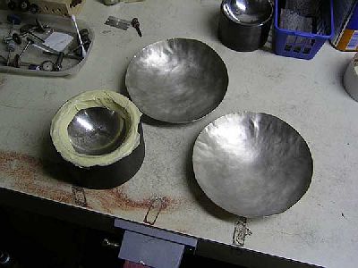
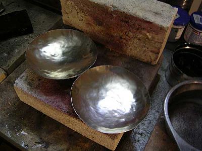
Now I move to the bigger die, and start working around the edge again.

You can see the difference between the two, the bowl on the left has been dished in the bigger die.

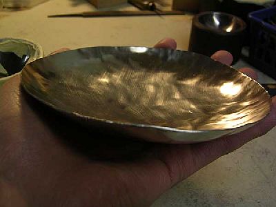
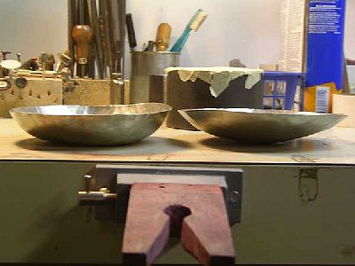
After I get the shape I want, I move into planishing. Planishing smoothes out the uneven areas and add some nice texture. I do this with my mushroom stakes and a highly polished hammer.
I clamp the stake in my post vise, and use light blows to texture it. Be careful not to hit too hard, and to always keep the bowl on the stake. You can start deforming the bowl very quickly if you don’t pay attention to where you’re hitting.
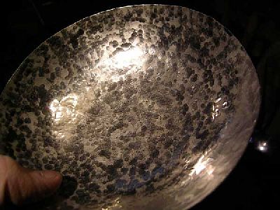
Here’s a close up of the texture, just the planishing took about 30 minutes. I finished it with some fine steel wool, to give it a matte finish.
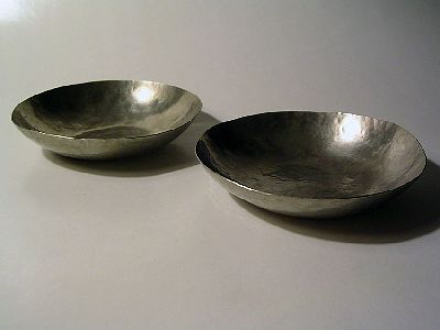
And the finished product.
-
IForgeIron Blueprints
Copyright 2002 - 2007 IFORGEIRON, All rights reserved
BP0291 Square Helper
by Irnsrgn
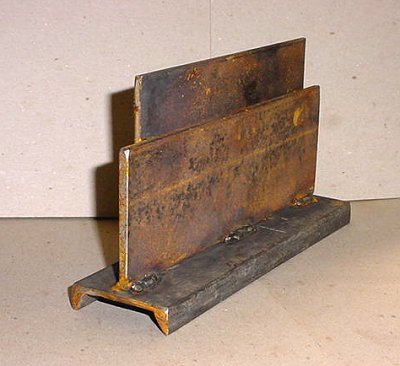
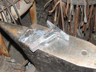
Just tack weld the piece of 2 inch flat in the center of the channel then tack weld the other piece to it. The 2 inch piece has to be square with the channel
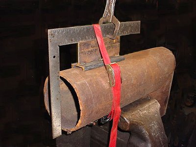
When welding a flange to the end of a piece of pipe, you need something to square up the flange to the center line of the pipe. The square has to go over the flange to get it square with the pipe, not easy to do without some sort of positioning device.This is so much easier to use than a 2 by 4 or some other jury rigging and the short piece of 2 inch channel is very stable and self centers on the pipe. Tack the flange in one place, use the tool and a square to get the other side square, tack weld, then rotate the pipe or the square fixture a quarter turn to square it the other direction. Tack weld and remove the fixture and weld the flange to the pipe or tubing.
-
IForgeIron Blueprints
Copyright 2002 - 2007 IFORGEIRON, All rights reserved
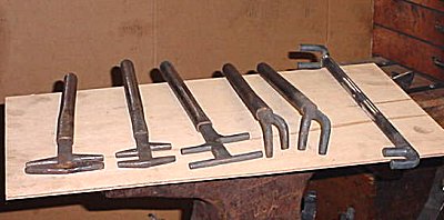
BP0290 Bending Forks
by Jr. Strasil
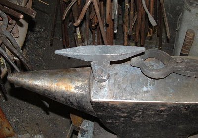
The big horns for the hardy hole.
The little hardy horns, notice the stop at the bottom to make it flat, I was using it once for a ring and it came out with a taper to the sides, as the bottom edge was not going completely against the side and was stretching the bottom side.
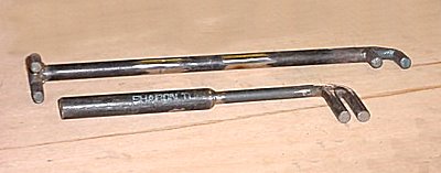
Ok, I know it looks mangled but its not, it is my version of side bending horns.
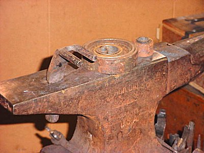
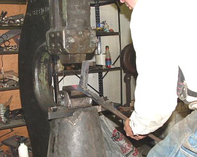
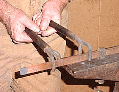
Shown here in the hardy hole with some of my short pipe mandrels. I am limited to how long a piece I can swing around on my anvil, so this way I can do a long piece by just pushing down.

The initial set up.
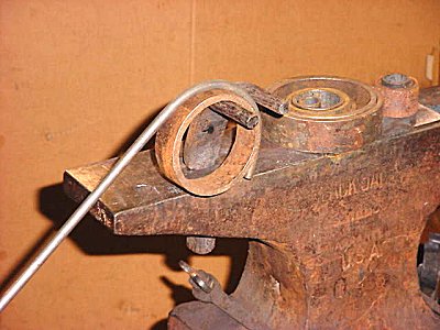
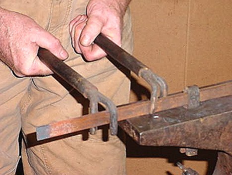
The second push down, just keep pushing it in and bending down.
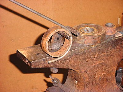
Farther along.
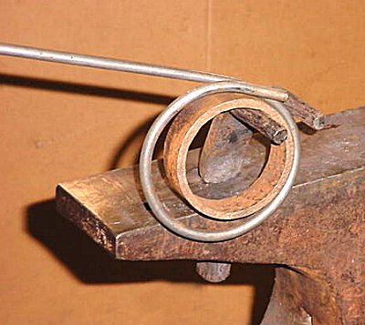
The completed ring, if it was done hot it would be more to the size of the mandrel.
-
IForgeIron Blueprints
Copyright 2002 - 2007 IFORGEIRON, All rights reserved
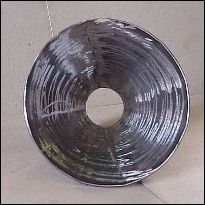
BP0289 Fan Puller
by Jim Carothers
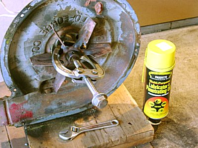
I wanted to remove this fan from an electric blower. At first, my small gear puller looked like it would work fine.
The problem is that the cast iron fan hub was quite a bit smaller in OD than the base of the fan. Without some sort of adapter, the arms of the puller would hook over the edged of the fan itself, and the pulling force would be against the fan sheet metal.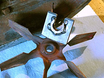
A small pulling adapter was fabricated from a piece of 1/4" thick shop scrap and a thick lock washer. The thick washer keeps the 1/4" plate from hitting on the backside of the fan sheet metal – the adapter / washer bears directly on the cast fan hub. The shaft in question is 1/2" diameter; the scrap was drilled 9/16” and then a hacksaw used to cut the slot. The lock washer was annealed, flattened, and tacked welded in place. The first slot was used as a guide to cut the slot in the washer.

This is a close up of the adapter against the fan. The puller arms will catch on the 1/4" plate and not damage the fan sheet metal.
With a little of Bayou Joe's favorite penetrating / lubricating oil (Howe's “since 1927” brand name), the fan came right off with use of only the 6” adjustable wrench on the gear puller. The home built adapter is now in the box with the rest of the gear puller stuff.
-
IForgeIron Blueprints
Copyright 2002 - 2007 IFORGEIRON, All rights reserved
BP0288 Gas Forge Burner
by Irnsrgn
All the talk about gas forges has gotten too me, my brain has been working overtime on this one for awhile, it finally came to a head, so I had to do something about it. LOL, So here goes, remembering that I sometimes think outside the box.

1 inch black pipe burner tube with the OD turned to 1.25 inches and threaded 16 TPI and the end relieved down to the bottom of the threads as I will not be able to thread the venturi clear up to the shoulder.
A short piece of 1.375 OD shaft just right for the purpose bored with a 3/4 inch hole and threads cut to match those on the burner tube.
The other side set to the taper of my cone and bored and a small shoulder cut to recieve the cone.
1/8 black pipe threaded 5/16 fine threads on inside and a 3/8 inch brass nozzle threaded and shouldered to screw inside the pipe and with an .052 hole for a jet.

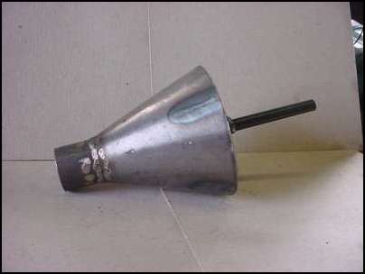
Cardboard pattern for my funnel shaped air intake.

Air intake funnel cut, formed, welded together, made of 16 gauge sheet.

Inside weld penetration ground off and splatter removed.
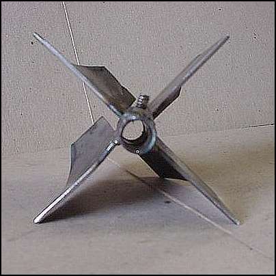
3/8 black pipe bored 27/64 so 1/8 pipe will slide thru, a 3/16 -24 nut welded to one end and then bored and tapped 10-24 for a set screw to hold burner jet tube in place using 4 fins with curved tips to get intake air to swirling so as to get a better fuel air mixture. Wire speed got bumped so that bad looking weld got ground off.
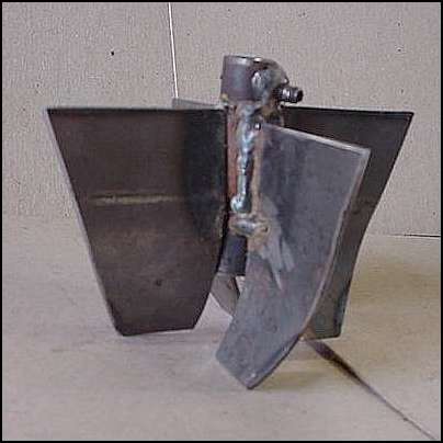
An end view of the tube holder.
Tube holder/fin component welded into funnel/venturi component, I used a small flat washer with the brass jet pushed into it to center the nozzle in the hole before welding.
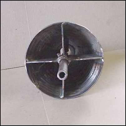
A view thru the venturi
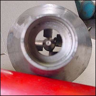
Air intake - venturi - nozzle assembly ready to be screwed onto burner tube.
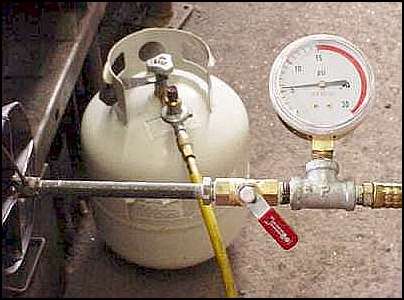
The completed assembly with a 1/4 inch ball valve attached.
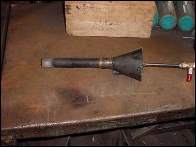
An end view of burner assembly with gauge and hose attached and an allen wrench in the set screw for securing the nozzle tube in the right place.
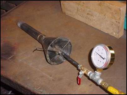
The actual operating pressure.
A quick jury rigged fire chamber set up to adjust burner and try it out. The top two bricks were set on their sides for the picture, in use they were covering the top of the chamber. This view is after 10 minutes firing time and 2 heats on a sample piece of 3/8 square.

-
IForgeIron Blueprints
Copyright 2002 - 2007 IFORGEIRON, All rights reserved
BP0287 Annealing Tank
by Gerald Franklin

Most of us have a container of annealing medium in the shop. This one is made from an old galvanized minnow bucket. It works well for smaller items such as a hammer or a few punches or chisels.
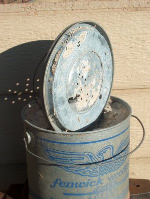
Take the strainer portion loose from the lid. Most of these can be chiseled loose fairly easily as they are held with just a couple of spot welds.
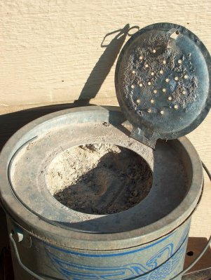
Fill the bucket with your favorite annealing medium. This one is filled with wood ashes from the fireplace. When you need access, just flip the small lid open, bury the item, close the lid, and go do something else. The lid keeps your medium from blowing out of the tank so it’s always ready when you need it.
-
IForgeIron Blueprints
Copyright 2002 - 2007 IFORGEIRON, All rights reserved
BP0286 Mini Anvil
by Mike-hr
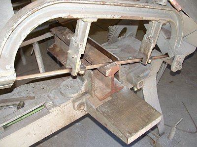
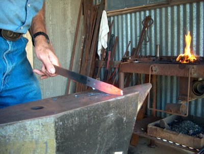
Cutting a slice of RR track 1 inch thick. I use light feed on the saw, takes about 15 minutes.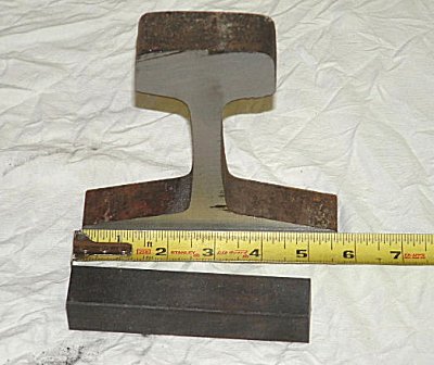
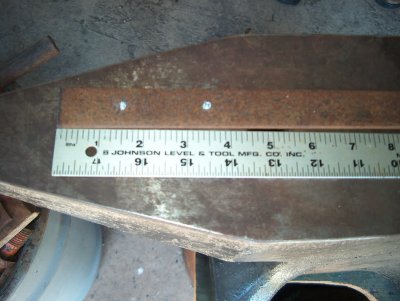
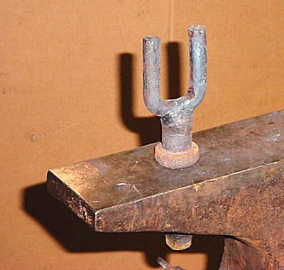
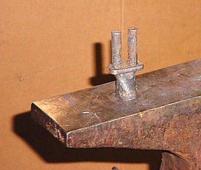
Cut the rail section from the bottom plate (see mark above the 3" measurement on the ruler). Cut 5 inches of 1" square or what ever size stock fits your hardie hole.
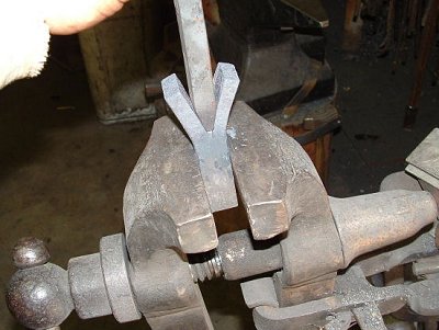
Split the square stock about 2 1/2" deep, and use a rounded punch to radius the bottom.

Cut the track to match the height of the 'Y'. I marked the radius of the punch on the track with a felt pen, and ground to shape.
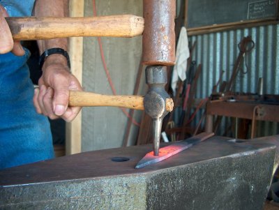
Hot seating the track into the 'Y'
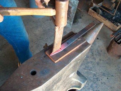
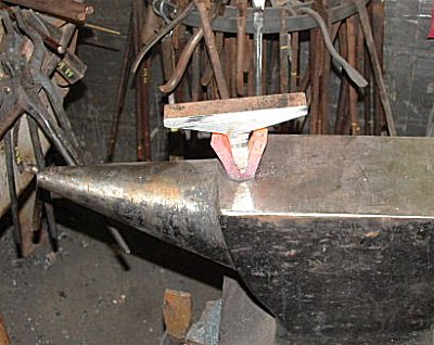
Getting ready to cleft weld the two pieces. A little MIG weld at the bottom helps keep the two pieces from squirting apart during the forge weld.

Finishing the cleft weld . Sticking the piece in the hardy hole helps contain it.
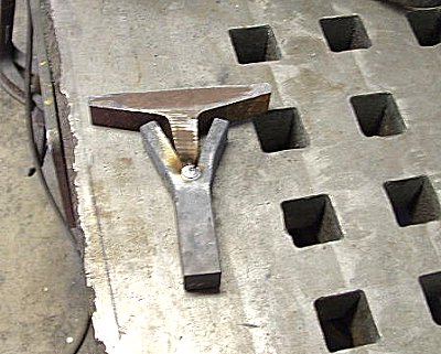
After it cooled, I migged around the cleft weld for added security.
Forming the bicks using Dick Sargent's taper refining attachment on the power hammer. (see Blueprint BP0081 Tapers Refined)+
After forging, I heated to bright red, and annealed in vermiculite over night. The next morning I ground the tool to shape, and hardened it in oil.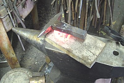
After hardening I finished polished and used hot blocks on the body to temper until the bicks turned brown/purple.

The finished mini Anvil.
-
IForgeIron Blueprints
Copyright 2002 - 2007 IFORGEIRON, All rights reserved
BP0285 Bending Forks
by Jr. Strasil
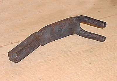
Some of my bending forks, the 3 on the left are just plain old bending forks with 2 different opening sizes on each one. The next 2 are right and left handed forks I use as a pair to refine scrolls. The last one is my version of Bill Elliot's that was given last week on the blueprints. I use pipe handles as they are easier to grip and stronger than a round rod.
Another view of my Elliott fork and another very narrow one I use occasionally.
Showing the position for curving toward the forks or for unbending a little, they are pulled toward each other when used like this.
The forks reversed and pulled apart to curve the piece away from the forks. I looks confusing but seems to work very well for refining scrolls.
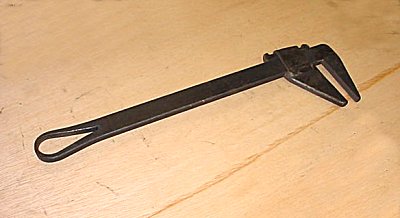
Another of my bending forks, adjustable for width of opening. I copied the design from an old smith made 4 ft monkey wrench I found.
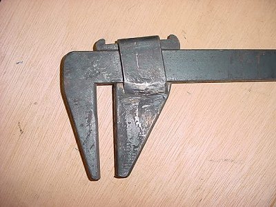
A close up of the locking mechanism, a tapered wedge.
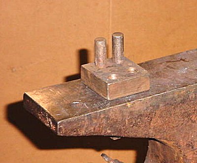
The adjustable horns I use the most.
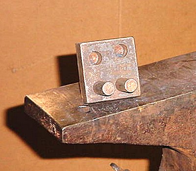
A view of the top, the pins are set for a 3/8 inch opening as shown, the other 4 openings available are, 1/2, 3/4, 7/8, 1 1/8 and 1 3/8 inch. -
IForgeIron Blueprints
Copyright 2002 - 2007 IFORGEIRON, All rights reserved
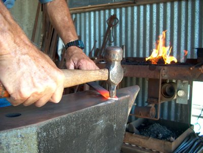
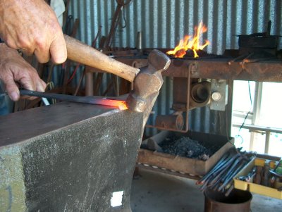
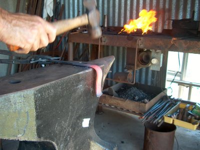
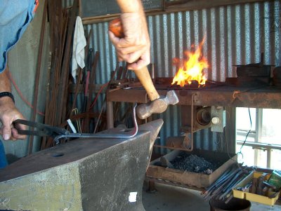
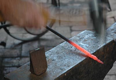
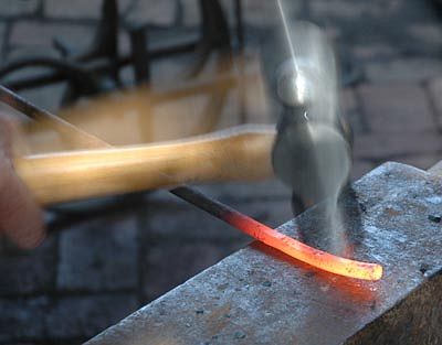
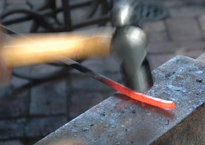
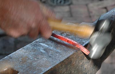
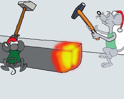
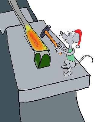
BP0284 Calling a Striker
by Daryl of Sasktachewan and Irnsrgn
No talking while striking - it's as useless as teaching a pig to sing; it wastes your time and it annoys the pig.
.....Smith requires a striker; Striker: 1 tap lightly on the heel of the anvil. .....Striker is ready and waiting for signals Smith: Strike and 1 tap on the anvil .....Signal for striker to commence striking where the smith is hitting Smith: Strike and 2 taps on the anvil .....Striker can take the next strike as normal, though his 2nd strike is an empty one (light) either on the heel or the horn while the smith repositions the iron (this is such that the rhythm may be kept) Smith: 1 tap afterwards on anvil .....Striker to only hit in the center of the anvil, as the smith will now move the iron to where the strikes are required Smith: 2 taps and drags the hammer .....Striker has one last strike and then is finished for this heat
Smith: 5 taps on the anvil
This is how I was taught (European). At first, I thought "well, I'll just humour him, he's probably the only one who does that", then one day, we had a few visitors in the shop, one fellow I had never met before. As I was lead striker and the other fellows who worked there were familiar with the signals, I tapped five times looking for a striker. This new guy walked up with the sledge and replied.... after completing the third heat, I introduced myself and asked him how he knew the signals. He replied that all who had taken the smithing trade in Germany were familiar with them.
It appears that only around here does no one know much about signals. An anvil choir is where there are at least two anvils and at least one smith and striker at each. Lead anvil has the master - he leads the whole shot; second anvil-smith listens to and follows the lead of the master; each striker follows the smith of his particular anvil. If you get a master with good musical sense (definitely not me), it sounds wonderful.
Most smiths in the US are not used to working with a striker, and I have not been exposed to European smiths working with strikers so I had no idea there were Universal signals. I have a couple of young smiths I work with occasionally and we use the signals taught to me by my father. When I was young I more or less grew up in the blacksmith shop and I was the striker most of the time when one was needed. The Signals I was taught; Smith 3 taps on horn when the piece in the forge is almost ready means a Striker is needed, come to the anvil. After striker shows up, there are 3 different sized sledges for the striker, 1 tap for 6 lb , 2 taps for 8 lb., 3 taps for 12 lb. After lead smith starts working on the piece. 1 tap for Start striking, after striker starts striking, 1 tap for softer blow, 2 taps for heavier blow, Lead smiths hammer laid on its side on anvil, Stop striking.
I also use 2 small platforms for the striker to stand on so that they can stand at the right height to deliver a fair and square blow with their sledge, from experience I have found out its easier to deliver a better blow and a lot easier on the strikers shoulders if they are at the right height for striking, especially when striking a top tool. And the sledge handles are cut off to about 24 inches so they don't have to fight the sledge handle to the side when striking. I guess I am what would be called an Old School Smith.
With a striker I am not familiar with, I just use words or set out the sledge I want used, and use words like softer, harder, stop.
Sometimes there are pieces of information that you don't want to let get lost. This article on talking to a striker has been placed in a Blueprint for reference, so we can find it easily. IForgeIron -
IForgeIron Blueprints
Copyright 2002 - 2007 IFORGEIRON, All rights reserved
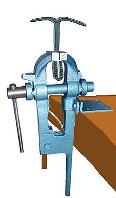
BP0283 Portable Drill Press
by J.W.Bennett (JWBIRONWORKS)
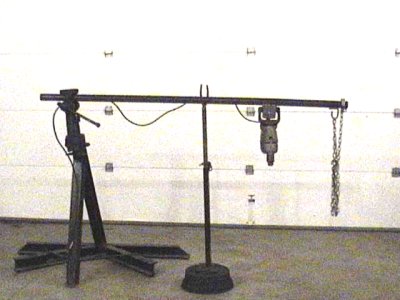
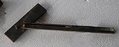
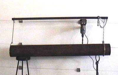
This is a variation of the portable drill press by Jr Strasil in BP055. I have used one just like the one we are about to make for over 20 years . I needed to drill 34 3/4 inch holes in the triple frame rails of a tri axle dump truck and was having quite a time. A mentor and friend of mine showed me how to make this. Although he has passed on now, I still Thank him every time I use it.
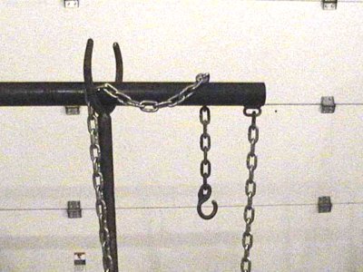
It starts with a 6 foot piece of 1-1/4 inch sch 40 pipe. Weld a 6 foot length of light chain (I use 1/4 inch) on to one end of the pipe. Add a hook to the other end of the chain. I forged this one but used store bought hooks for years.
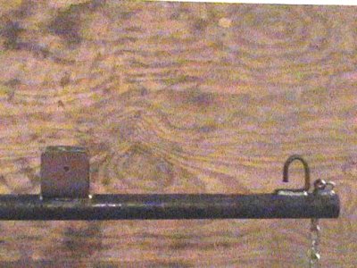
Make a saddle to hold the drill out of plate or angle. I use plate bent in a U shape to fit the spade handle on my drill. Weld it on to the pipe 18 inches down from the end you welded the chain on.

Since I use a spade drill I place the drill handle in the saddle and Drill a hole in both sides of the saddle and make a pin to fit in to the holes to hold the drill in place. I attach the pin to the saddle with a short piece of chain to keep it from getting lost.
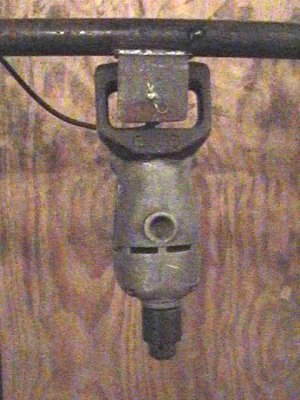
If you are not using a spade drill you might not be able to pin it.
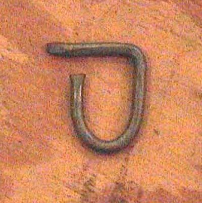
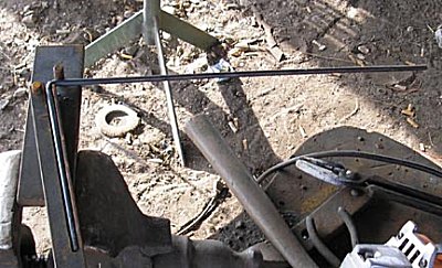
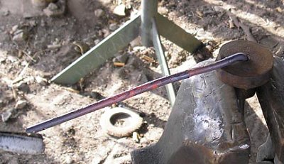
Take a short piece of 5/16 rod and bend a hook like in the next picture. Now weld it right behind the Chain you welded on the end of the pipe in the first step.

As you will see later on this will make adjusting the chain length much easier.
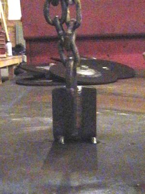
To use the jig you wrap the chain around the Piece you need to drill (I Beam, Channel, Pipe etc...)And hook it to itself. Once you have your drill in place then you can adjust the chain using the 5/16 hook you welded on earlier.

You can get a lot of leverage with this rig and if the drill tries to catch it does not wrap you around the work piece or break your wrist. The handle is long enough You can stand back and eyeball if your level and square.

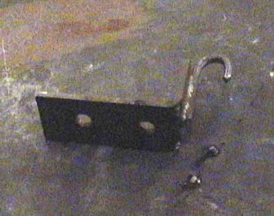
I have made several L brackets out of scrap iron with 5/16 hooks welded on the top. I tack weld these to larger work(like Plate, Bin walls, tanks etc) that you can not get a chain around. Just tack weld the front bottom edge of the angle to the work. Or drill a couple of holes in the bracket to bolt it down if there are any holes in the work piece. Then attach the drill rig chain to the hook on the bracket.
To remove the bracket when your done... If you tack welded it on you bend the bracket back and forth or smack it with a hammer to break it loose. Grind the tack off of both pieces and your done. If you bolted it on simply unbolt it.

There are probably several refinements that could be made to the drill rig. however I have used mine for many years just the way it is. If you have several holes or large holes to drill this tool will save time and effort.
-
IForgeIron Blueprints
Copyright 2002 - 2007 IFORGEIRON, All rights reserved
BP0281 Upset Helper
by Jr. Strasil
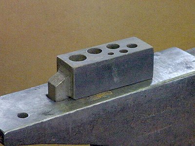
This is one of my upset helpers. It's just a short scrap of 2 inch square mild steel with holes bored in it. 3/8, 1/2, 5/8, 3/4, 7/8 and 1 inch all at least 1/32 oversize, with a hardy shank welded on the end.
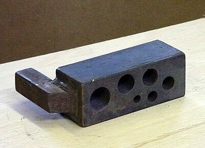
This is the view from the top
.
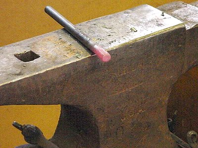
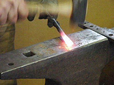
The end upset just a tad with a short heat and the edges beveled with a hammer on a piece of 1/2 inch hot rolled for a bolt. Most people heat to much of it when upsetting and it just bends over. (Rule of thumb is 2.5 times the diameter for a bolt head.)

Starting the upset with about the right amount hot on the end. its already starting to bend to the side, if you are not using some kind of restraint, now is the time to straighten it.
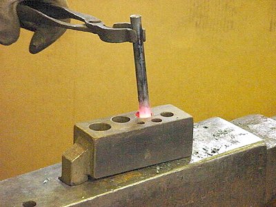
With my upset helper I just stick it in one of the holes that will let it expand some and hammer on it till it gets too cool to upset anymore. It can't bend much sideways so more work is accomplished as the straightening can wait till the end.
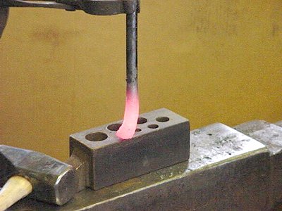
This is what it looks like right from the upset helper hole.
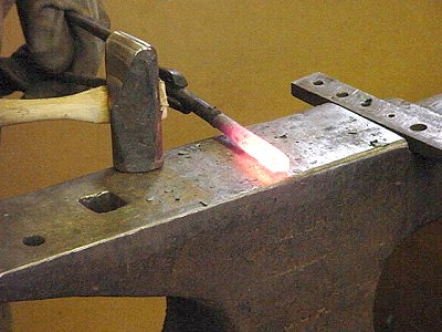
Another heat and straightening it and beveling the end a little.
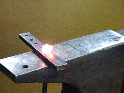
Squaring the end some prior to heading, notice that one side is longer than the other, this should have been cut off, but I decided to leave it to show what will happen.
In the header and the initial heading done. (notice what happened to the side that was longer). This is very hard to correct now and will never be right.

Another heat and squaring the head up.

Back in the header for making the final head thickness.
The final thickness achieved.
Final finish squaring of the head, a hand made bolt head will have a tell tale slight bulge in the center of each side due to this final squaring and have a slight depression in the center.
What the finished head looks like at a dull red heat.
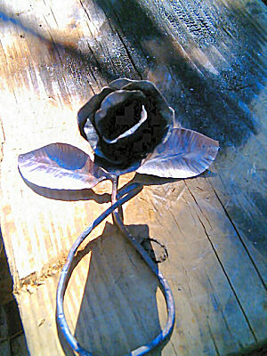
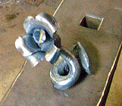
BP0455 Rail Road Rose
in BP 400 Series
Posted
IForgeIron Blueprints


Copyright 2002 - 2011 IFORGEIRON, All rights reserved
BP0455 Rail Road Rose
by Marc Godbout
:
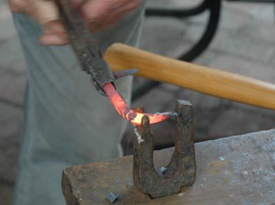
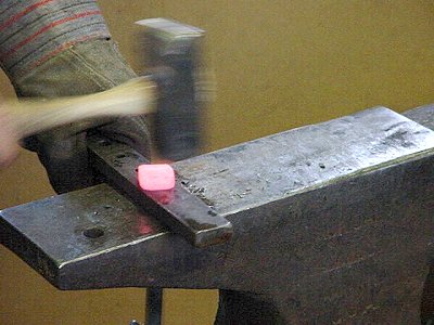
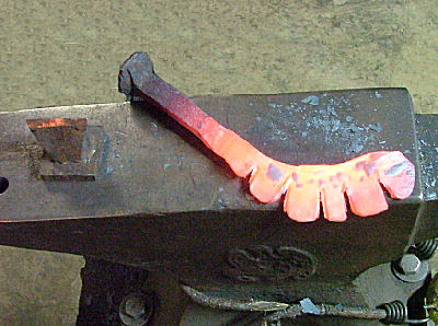
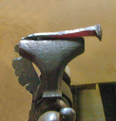
I started with a normal, "found", spike.
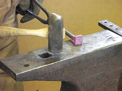
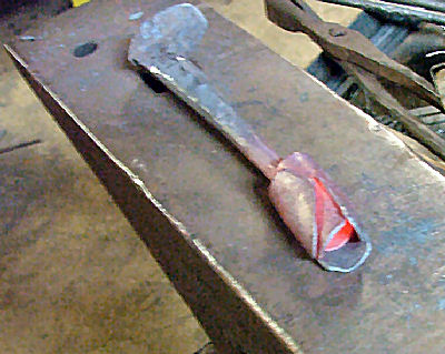
Forge about 1/2 of the end so that the end is wider than the middle. Those will be the outer petals. This one has the end about 2" wide. It will get wider later. It's about 1/8" thick at this stage.
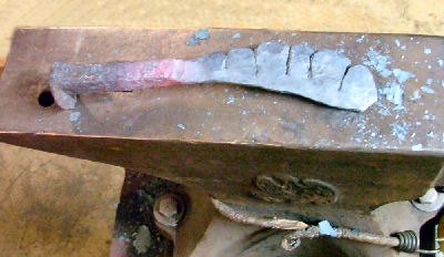
Then cut the petals. Before making the cuts, I indent the place where the cut will be going with a cold cutter. This will round the corners of the petals. Sorry about forgetting to get a picture of this step.
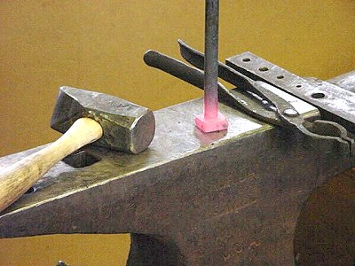
After the indent, make the cuts about half-way through. I chiseled these, but I used a band saw on previous roses. Either way looks good, but the petals need to be cooled down if using a band saw.
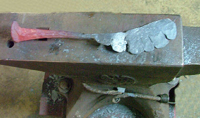
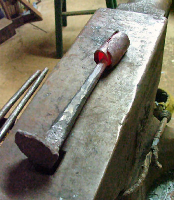
Here I straightened out the petal section and used a rounding hammer on each petal. You can see some overlap on a couple petals. This step rounds out the the petal tips and sides, while thinning to about 16 gauge. You need it that thin to roll and form later. The petals section gains some length, too, to about 2-1/2" at the end.
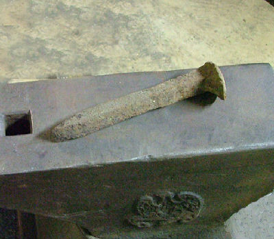
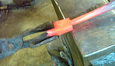
Now we draw the stem down. But notice that the stem is even with the back of the petals, making a shoulder of sorts where the stem meets the petals.
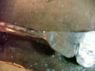
This is a bit out of focus, but you can still see the "L" shape where the stem meets the petals. This "L" will be straightened out next.
And here we bend the petals down, which straightens out that "L". I see I'm still having problems with the focus, though, but it's clear enough.
And here's the final shape before rolling.
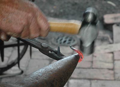
I started the rolling by gripping the petals in the vise and hammering the stem down over the petal. Then I just grip the stem end in tongs and roll, while hot, on the anvil and hammer it tight. Roll it straight down the middle. These two pictures show that the outer petals hang out over the inner ones about the same amount at the tip of the flower as at the base.
Then I grip the flower end with my round bit tongs, while bending the base of the flower in. I use the near edge of the anvil for this. My anvil has about a 1/4" radius to it. You could probable use the horn, too. The round-bit tongs keep the flower rolled while working the base.
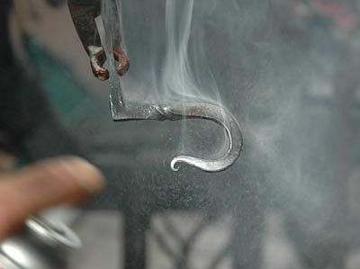
And here's the final product. I use my little scrolling tongs, which were once round needle-nose pliers in a previous, but unfulfilled, life, to form the petals. Bigger scrolling tongs and some forging were used to form the stem.
That's about it. I finish mine with a Rustoleum Satin clear coat. Happy railrosing!