

Steve Sells
-
Posts
9,156 -
Joined
-
Last visited
Content Type
Profiles
Forums
Articles
Gallery
Downloads
Events
Posts posted by Steve Sells
-
-
Posted 04 September 2011 - 02:42 AM
IForgeIron.com Blueprints
Copyright © 2002 - 2011 IFORGEIRON.COM, All rights reserved.
BP0788 Leaf Swage
by Jake Pogrebinsky
Posted September 4, 2011, 05:40 AM
http://iforgeiron.com/content/blueprints/700/788/01.jpg
This is hardly an example of anything worthwhile, but just makes it easier to discuss the principle.
The more convex the "buttocks" are, the more aggressively you can deform the parts of the leaf that lay on them.
And, if your blank is slightly larger, and you don't hit the very perimeter, the edges, then the original thickness will remain there. Allowing, I think, for all kinds of cool possibilities!
. -
IForgeIron.com Blueprints
Copyright © 2002 - 2011 IFORGEIRON.COM, All rights reserved.
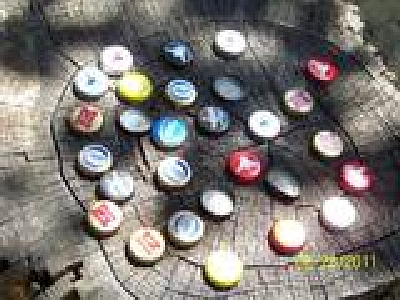
BP0789 Bottle Cap Fun
by trying-it, Stan
Posted 06 September 2011 - 01:57 PM
What can you do with a bunch of bottle caps removed when opening your (and/or your friends) favorite bottle of refreshment? Most caps of this style are made of steel. Either the newer twist off caps or the older style needing a bottle opener can all be used.
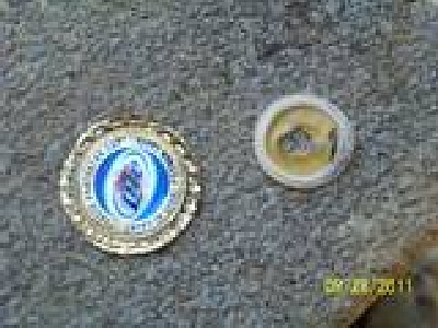
Remove the plastic sealing liner inside the cap. Warning: they are stuck in there real good!
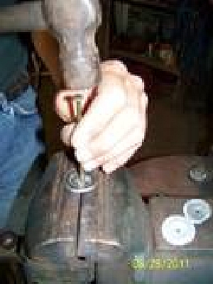
Flatten the caps somewhat.
Punch a hole for the stem/mounting wire. I use a hammer and a sharp nail about the size of the wire to be used and notice how I barely have my vise jaws opened a crack to allow for the nail point to penetrate, but not bend or distort the flattened or semi-flattened cap.
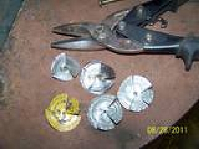
Using some type of metal snips, partially cut a varying number of slits (I use a combination of 2, 3, 4, slits in each rose) in each cap to be later worked for the individual petals. More slits =short and more petals, Less slits = larger/longer petals
Stack 5 or 6 caps together and attach to the end of a steel wire using your favorite method.I usually just weld the first and last cap on the wire as the center ones will lock up against themselves during the fluting process.
I have used solder, braze, and have A/O welded them on with mild steel rod (Nice to have a Henrob torch for that !!!!)
!!!!)
Now just flute each individual petal (cold) with a pair of scrolling tongs, needle nose pliers, etc) to make it all look like a rose.
Apply 1 or 2 drops of your favorite floral scented oil just before handing it to someone (find in candle making dept etc), and you now have a bottle cap rose(s) that look good and smell great!
Finish can be any color paint from cans or paint sticks (as used to mark steel), hot brass if you heat them a little after fluting and use a brass brush, or any other patina finish you desire. I spray clear enamel on finished roses to prevent rusting.
Have fun making some and remember the edges of those caps are sharp so work with a little added caution.
What can can you make using bottle caps as the starting material?
Thomas Powers
Posted 07 September 2011 - 09:41 AM
Back a decade or so ago there were folks in the neo-tribal blacksmithing groups that were making bottle cap pattern welding at their full moon smithing parties.
I use them for the tails of rasptlesnakes---I have to put about 300 on snake tails this week. Of course I employ a crack team of experienced college students to produce the raw materials for me...
-
IForgeIron.com Blueprints
Copyright © 2002 - 2011 IFORGEIRON.COM, All rights reserved.
BP0790 Cala Lillies
by Thomas Dean
Posted 17 October 2011 - 10:28 PM
Here are some Cala Lilies I made back in the spring for an exhibit of my art work.
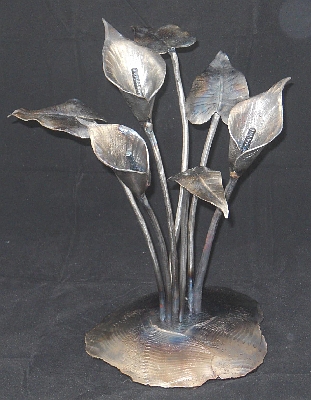
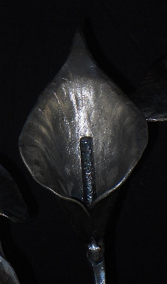
The lilies are made from 3/4"rd bar and range from 10" to 12" tall and 1 3/4" to 2 1/2" dia. The 'spadix' (thinggy in the middle of lily ) is 1/4" rd and textured on a farrier's rasp using a wood mallet. The leaves are made from 1/16" steel sheet (sorry, don't know my guage sizes) with the stems of the leaves from 1/4" rd. The base is 1/2"plate. My dear wife let me use one of the leaves off her Cala Lily to use as a pattern.
This was the first thing I made with my newly purchased NC gas forge. Started out just heating up the 3/4" rd bar and playing, chunked the pieces on the floor (scrap area) and came back a week or so later and thought maybe I could salvage them into something....
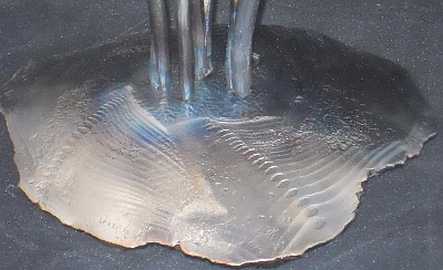
As to the texture on the base....dunno how that happened other than something had stuck on the top die of my power hammer! The little "disc" shapes were the results. I saw it on one side and liked it and move around the plate doing the same thing. The center area was left at the original thickness and then dished to stand 1 1/2" tall. Wire buffed all before attaching to base, heat colored, polyurethane fininsh. -
IForgeIron.com Blueprints
Copyright © 2002 - 2011 IFORGEIRON.COM, All rights reserved.
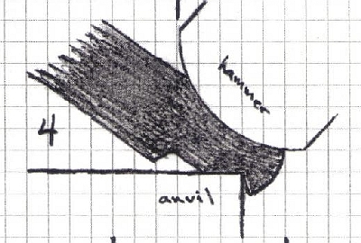
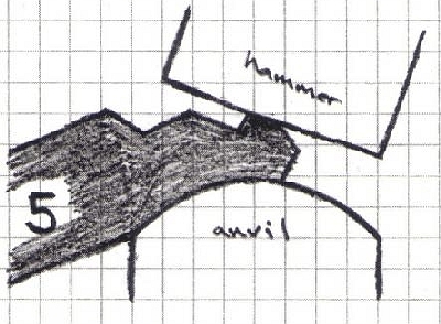
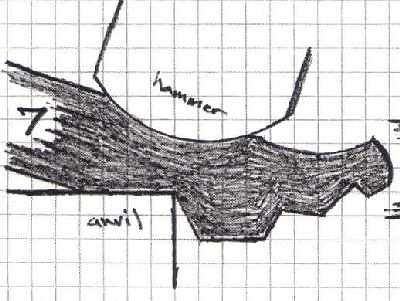
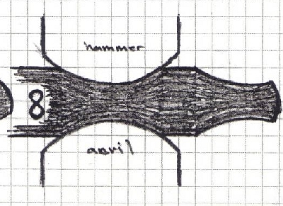
BP0791 Horse Heads
by Brian Brazeal
Posted 22 March 2009 - 09:14 PM
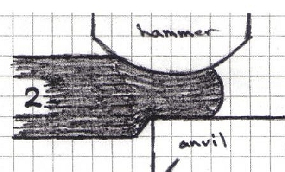
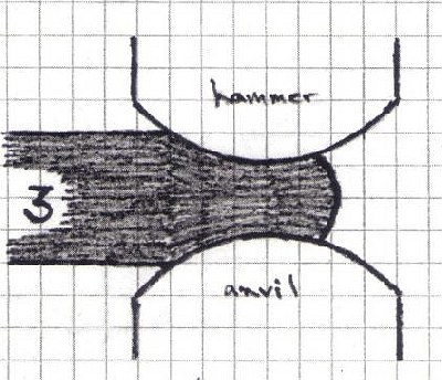
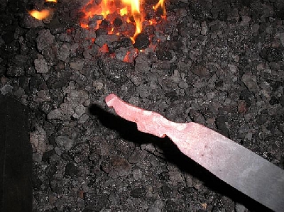
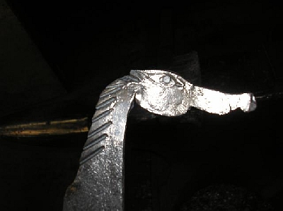
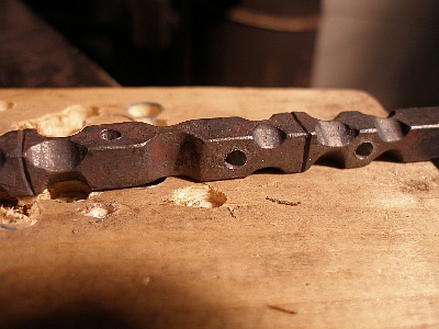
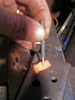
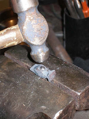
I made some quickie animal heads today out of 3/16-inch by 1/2-inch, as a suggestion of something for others to try. They are made with half hammer faced blows over the near and far side of the anvil on a sharp edge. This picture shows the steps of a horse head, and if you look you can see where the round hammer makes sudden divisions in the metal while holding the material on or over the anvil. The horse can be done in one heat with practice. They are similar to making tongs. You can make many other shapes and animals with this same technique. I'm including a drawing I made over 15 years ago of how to do a 3D horse head, which should help to see the angles that you hold your material. With the flat stock, you leave the top and bottom round dies, step out and just check your material on the flats.


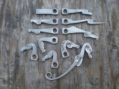
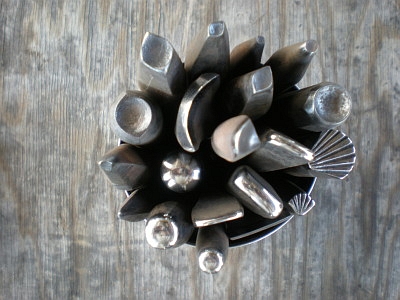
Posted 24 March 2009 - 03:23 PM
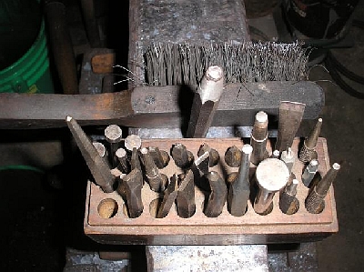
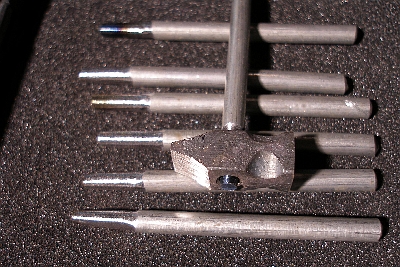
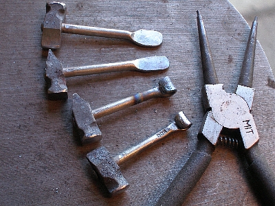
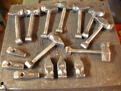
Here are the tools besides my hammer, anvil, and vice that I use to make animal heads out of flat bar or square stock for the 3D heads. Notice that the eyes and noses are made from square punches, that I leave two corners on, so I know how to oreint my punch. Except for the round ones where it doesn't matter.
Dick L
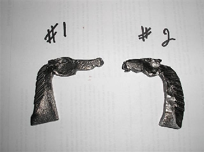
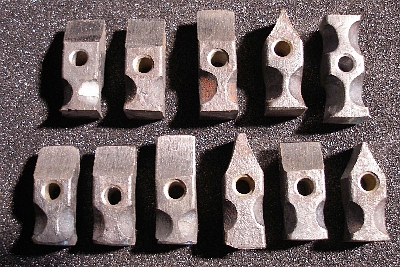
Well, I said I'd post when I gave it a try and here it is. I can tell you, I'm a long ways away from a one heat horse head. :DThis is about number 6 or 8...in all the excitement I lost count. I still need to make a rounding hammer like Brian's drawing shows, but I did do some punches and chisels. I would have gladly gone for #2 tonight but the rain has reached central MA. and I still work under the stars. 
On the next one I'll pay close attention to the near and far side strikes so it doesn't have the crocodile snout...
Well, I went at it again tonight paying close attention to the anatomy of the head and trying to get as much done per heat as possible. I used 8 heats to get it to this point, and if it weren't for the giraffe-like neck I would be pretty happy. This is 3/16-inch by 1-inch stock and it cools pretty quickly. I am walking about 10-feet from the forge to the vise. I don't have a portable setup yet. The anvil is right there close up though. I think I'll concentrate on getting things arranged better so I can work more efficiently.
Brian Brazeal
You're doing fine, but I would suggest starting with 1/4-inch by 3/4-inch. It is a much easier profile to manage. The proportions will come. Think about forging the rectangular profile to square at the chin and the base of the neck and a smaller rectangle at the first notch in front of the cheak. The first notch sets up your proportion, and you can take less than you'd think from the start. The cheaks are basically a square of the material. The half hammer face blow allows you to isolate the material, as I can see you've already got that down. Keep up the good work. Karen gives you a "Whoo Hoo!" -
IForgeIron.com Blueprints
Copyright © 2002 - 2011 IFORGEIRON.COM, All rights reserved.
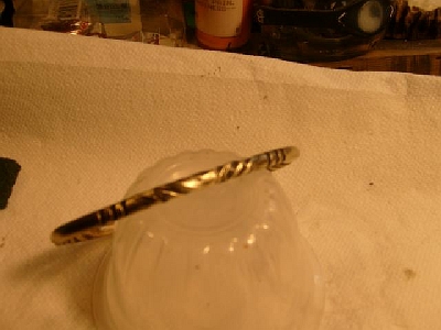
BP0792 Brass Twisted Braclets
by Garey Ford
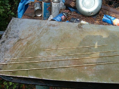
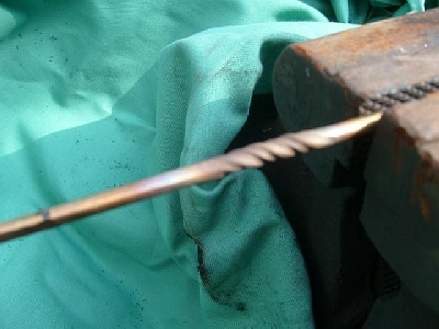
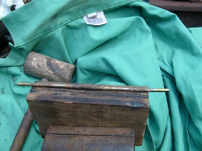
Twisted brass rod bracelets made from 1/8-inch brazing rods and 3/16-inch rods for larger bracelets.
The 1/8-inch and 3/16-inch rods are cut to length and marked where they will be squared up. The lady's bracelets are 7-inches long, and the men's bracelets are 8.25-inches long
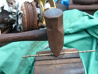
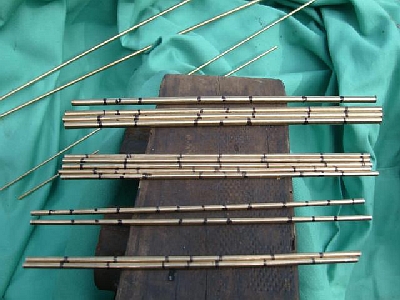
The rods are squared up on 4 sides where marked, so the twist will show up. The smoother the section is the sharper the twist will look
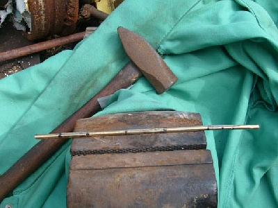
Each section marked, is squared up and ready to be twisted.
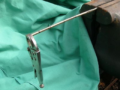
Clamped in the vise and ready to twist with the vice grip on the other end.
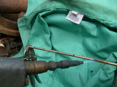
Heating the first square section to twist. Use a small brazing tip and go slow with the heat and twist slowly.

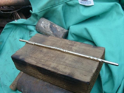
First twist done 1/2 of a rotation.
First twist fully twisted one turn of the vice grip. if you like a 1/2 twist go with that . There are many variations of twists that can be done to change the looks up.
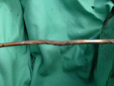
A double reverse twist in the middle of the bracelet. Twist 1/2 of the twist clock ways. Let cool and heat and twist second section counter clock ways to get a reversed twist.
The bracelet all twisted in the center and at each end.
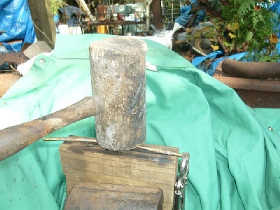
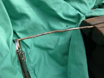
Straightening the bracelet up on a piece of wooden 2x4 with a wooden mallet.
The brass rod all twisted up and straight.
Rod straightened up and polished
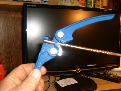
Bending the ends with a tubing bender. I got this bender from Harbor Freight. The very ends are harder to bend around and the tubing bender makes it easier.
Finishing the bend using a wooden mallet and a piece of pipe.
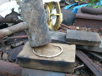
Flattening bracelet on a piece of 2 x 4 with a wooden mallet
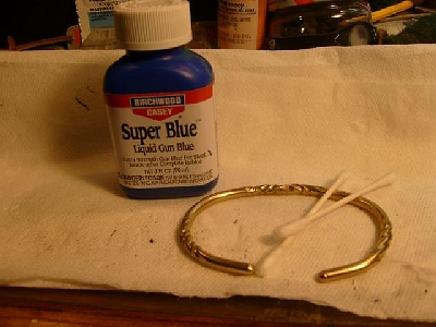
The bracelet all twisted and shaped, ready to "age " with gun blueing.
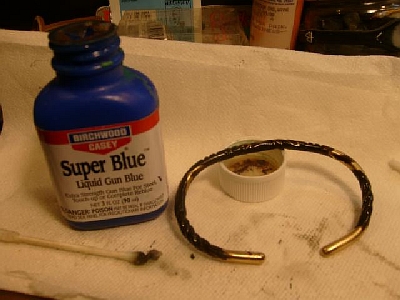
Gun bluing applied to the bracelet with a cotton swab.
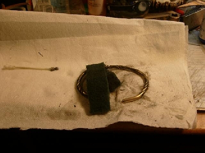
After the bluing is dry, lightly scrub the dark bluing off with a green scrubbie pad, leaving the dark bluing in the twists to *age* it.
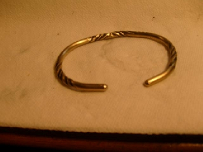
Finished bracelet!
Top view of finished bracelet.
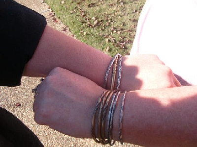
The wife's and niece's twisted bracelets. Some are nickel silver, some are 1/8-inch brass. You can do all kinds of different twists on the rods. These are just simple twists.
-
IForgeIron.com Blueprints
Copyright © 2002 - 2012 IFORGEIRON.COM, All rights reserved.
BP0794 Holiday Ornament
by Sam Falzone
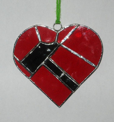
I have this great little hole-in-the-wall cafe a few blocks from my house that has become one of my favourite spots. It is always friendly and it's a great place for neighbours to gather. Coincidentally enough it's called "the Heart of the Hammer". I decided to make a stained glass ornament for them (because I happened to have some stained glass scraps handy) and while stained glass is not your typical blacksmithing medium, I did add my own smithing flair to it (with a name like Heart of the Hammer, you know I was gonna )
Hope you all like it.
Sam -
IForgeIron.com Blueprints
Copyright © 2002 - 2012 IFORGEIRON.COM, All rights reserved.
BP0795 Wheel Spanner Candle holders
by Mr Smith
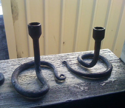
I had a bunch of wheel spanners lying around. Not anymore
Frank Turley
The jolly old English language. I had a student from Colorado who was brought up in England. He was calling any wrench in my shop a "spanner," using it as a generic term. I told him that to me, a spanner was a handled wrench with 2 nubbins or tits which spanned a specific distance and engaged with two appropriate holes. He agreed, but insisted that any wrench was a spanner. Therefore, I had a double take on "Wheel Spanner Candleholders." Then, it registered; Mr. Smith was talking about what we in the U.S. call a lug wrench. -
IForgeIron.com Blueprints
Copyright © 2002 - 2012 IFORGEIRON.COM, All rights reserved.
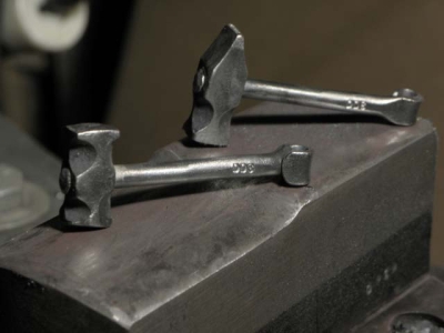
BP0793 Key-Ring Hammers
by Don Sinclaire, 2011-12-08
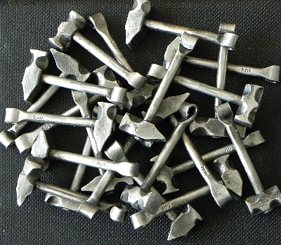
Material: 3/8 inch square hot rolled mild steel, 3/16 diameter mild steel for the handles
3/4 inch diameter split rings for the key rings
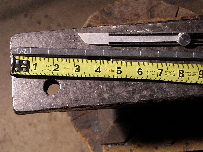
The hammers are made in batches, on a continuous strip. Take a 12 to 16 inch length of 3/8 inch square HR steel and place a mark at 7/8 inch increments using a sharp soapstone. The hammer heads will be made in pairs, back to back.
With a cold chisel, score a line around the bar at the second mark, fourth mark, sixth mark etc. This is where the faces of the hammers meet, and is the line on which you will cut them apart. You need this line in order to position the fuller on the four corners near the face of the hammer.
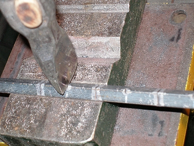
Nick the corner of the bar at the first, third, fifth soapstone mark. This will be your reference mark to fuller the back-to-back peins of the hammers.
All this is done cold so far.
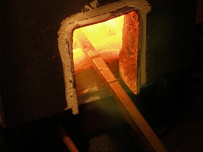
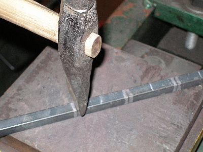
Heat the bar to a yellow heat.
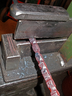
Use a spring fuller (or guillotine fuller or smithin' magician) with 1/4 inch diameter (1/8 inch radius) dies and fuller the corners of the bar centered about 1/4 inch back from the reference line. Then fuller the face of the bar at the nicks to form the peins. Don't go too deep yet because the bar will become too flimsy. Square up the edges. Do one or two hammer heads at a time, and work your way back along the bar. Keep the bar straight and square. I used a 1/4 diameter fuller for the peins, but a 1/2 inch diameter would have required less dressing in the finishing stage.
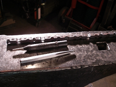
Make sure the bar is straight so that it rests on the anvil and later on the drill press properly without rocking. Use a small automatic center punch to mark the holes for the handle. Angle the punch if necessary in order to "move" the indent to where you want it, and then use a regular center punch to place a clear mark for the drill. Don't place the mark too close to the pein end of the hammer, especially if you only used a 1/4 inch diameter fuller, since you may want to grind or file a better shaped pein later. You can mark the holes for some hammers on the "top" face of the bar for cross pein hammers and some on the side for straight pein hammers.
Drill the holes with a 5/32 inch drill. Remove burrs with the tip of a 1/4 inch drill.

Cut the heads apart between the faces at the score mark and the peins.
I ground the peins using the 2-inch diameter idler on my belt grinder, since I don't have a wide enough fuller for shaping the peins. Also grind the faces if they look too long or have crooked saw marks on them. You might have a few rejects if the holes are not centered or if the fuller marks are not lined up properly.
Cut the 3/16 inch round stock to 2 - 1/2 inch lengths. Grind about 1/2 inch of one end down a bit, with a slight taper to fit part ways into the hole in the hammer head. Don't make the tip too small, or you won't have enough material to rivet the end over.
Heat the hammer heads to a yellow heat. A propane forge is best, so that you don't loose them in the fire. Place the heated hammer head on a bolster plate, insert the (cold) handle and pound it into the hole so that about 1/8 inch sticks out. Quickly quench just the pein and upset the hammer face to give it a slightly rounded worn look. If you make sledge hammers, you don't need to quench - just upset one face, turn it over and upset the other face. Do this quickly in one heat.
Trim the tip of the handle so that only about 1/16 to 1/8 inch sticks out of the head.
Place the handle in a smooth-jawed vise with the hammer head about 1/16 inch above the jaws. Pein the end over, in order to keep the handle from coming loose.
Heat the end of the handle (coal forge or torch works best here). Use half face blows to flatten the end of the handle. Keep the sides parallel to form a tab about 1/4 inch wide and 1/2 inch long. Heat the end again and roll up the tab leaving a hole large enough for the split ring. I used a pair of snap ring pliers as scrolling tongs.
Wire brush the scale off, add your touch mark, coat with warm bees wax and run the split ring through the hole.
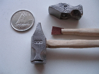
You might want to put wooden handles in some of your hammer heads. Here I made a handle out of a sliver of ash and made a wedge out of an even smaller sliver of rosewood that was on my workbench for a year (too nice to throw out - you never know when you might need something like that!)
-
IForgeIron.com Blueprints
Copyright © 2002 - 2012 IFORGEIRON.COM, All rights reserved.
BP0796 Christmas Star
by Junksmith
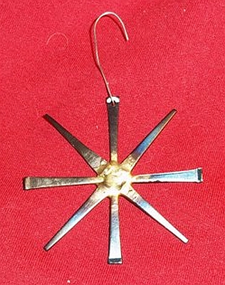
These are fun and easy. No forging really. I just arrange old masonry nails in a star pattern and braze them at the center. The large puddle of brass is unnecessary for making them stick, but it looks nice. Once I pickle them, I heat them with a blowtorch until temper colors start to show and dip them in oil (while still hot) for a finish.
One problem I ran into was that the nails were very hard to drill for a hanger. As the last step in assembly, I heat the area I'm planning to drill up to red and let it cool. Much easier to drill then.
They sell like hotcakes at Christmas for $5 each and make great giveaways as well. -
IForgeIron.com Blueprints
Copyright © 2002 - 2012 IFORGEIRON.COM, All rights reserved.
BP0797 Fire Grates
by Suboc
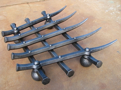
Here is a fire grate I just finished for a local client. Forged from hex bar, and utilizing mill balls as feet..
Dan
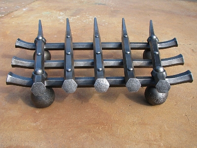
Here is another shot from the rear of the grate.
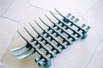
And last, this is another grate I made a while back. It is similar in construction however fits into a fire box on the corner of a wall.
.I heat the mill balls in the forge till glowing. I've never concerned myself with how hot but I get them yellow and let them soak for a while. Then I shut off the forge leaving the balls in and close it up...the next morning you can drill and tap them. Prior to that you can't even touch them with a center punch. The feet in question have a rivet that passes throught the entire ball and is upset top and bottom. On the first grate it is a 3/4" rivet the last grate it is around 5/8".
-
IForgeIron.com Blueprints
Copyright © 2002 - 2012 IFORGEIRON.COM, All rights reserved.
BP0798 Working With Hex Bar
by Suboc
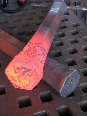
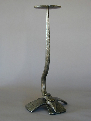
I like working with hex. It has an interesting look when slit and drifted, upset, drawn out etc. Here is a large sculpture utilizing 3 1/2" hex bar.
And a large candle holder I made back in 2000 that started out as hex and ended up as ?
-
IForgeIron.com Blueprints
Copyright © 2002 - 2012 IFORGEIRON.COM, All rights reserved.
BP0797 Trammels
by Jake Pogrebinshy, John N

Jake
A simple trammel from earlier this week.
John N
I would regard your "Simple trammel" as a de-luxe model, This is a simple one.
Two bits of as it comes stock, with minimum work to do the required job.
The reason the old timers worked the stock was that it was not available in an appropriate size, and they had to work it down to the sizes the wanted, this may include forge welding many bits together to produce the required dimensions. They would have killed for the stock sizes that we have available to 'smiths today.
Then, as now there was a varied market for products, look at a store shed for simple work, or a Bishops Palace for high end work. Value added is put into the piece for the market it is aimed at. -
YES always
Sadly we stopped hosting the Tuesday night BP presentation because Glenn and I could not do it anymore, and no one else would commit to being in the chat room every Tuesday to present them, but I will still add to this list when they get sent it, I will format them if you cant as well.
I also added some of the 200, 400 and 600 series today, still so many are missing drawings or photos
Perhaps someone would be willing to go over the old ones like that and re do them?
-
IForgeIron Blueprints
Copyright 2002 - 2011 IFORGEIRON, All rights reserved
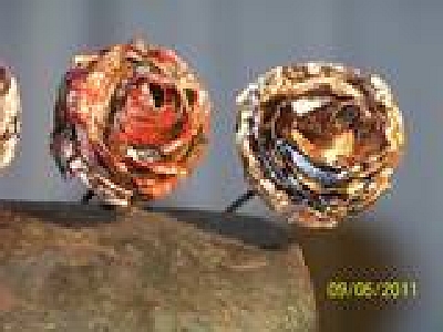
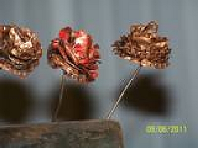
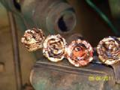
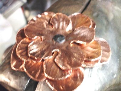
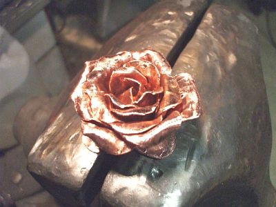
BP0635 Layered Rose of Copper
by Richard Thibeau
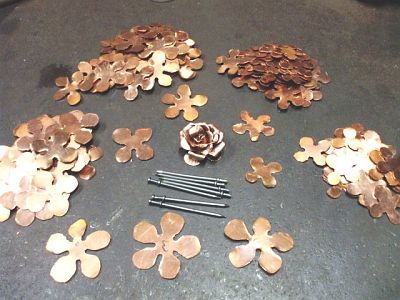
I have a commission to make more than 40 roses out of copper. These are the pieces cut out and separated by size. The final flowers will be about 2 inches in diameter.
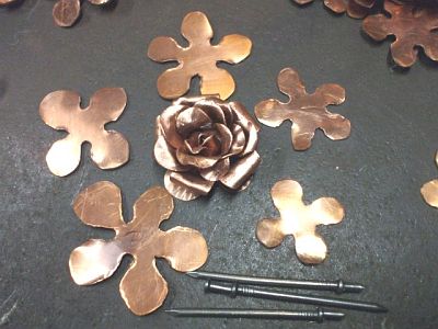
Closeup of the individual layers and a completed rose. The duplex nails are the stems, the top head is cut off.
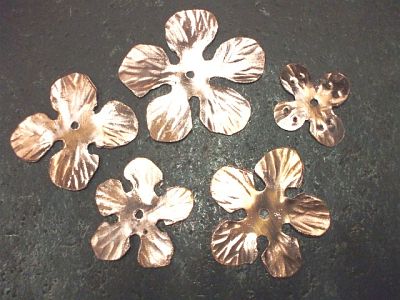
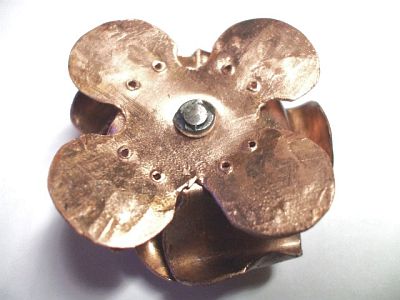
The five layers with the petals textured and wire brushed, center hole drilled to mount on the duplex nail. The smallest piece has extra holes for thread as these flowers will be sewed onto fabric.
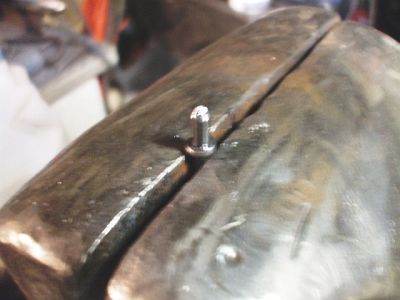
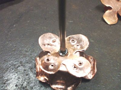
The duplex nail with the top head removed is set in the post vise. All layers will be pushed onto the nail, the lower head of the nail makes a fine stop so that the layers stay together.
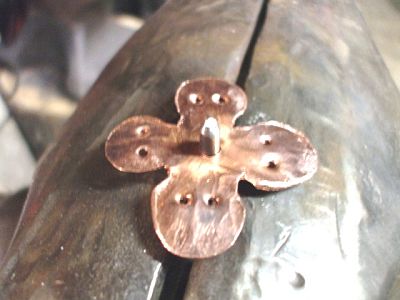
The smallest layer is put on first so it will be on the bottom to be sewed onto fabric later.
The rest of the layers are in place...the largest on bottom, smallest on top.
The nail stem is peined over to lock the layers in place, a simple rivet process.
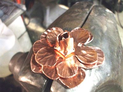
The petals are folded up one layer at a time. These were done cold as copper is soft, but they could be heated for the heat colors to show on the copper.
Layers are continually folded up to make a bud of the petals.
All layers have been folded up into a bud. The bottom layer is left flat on these flowers.
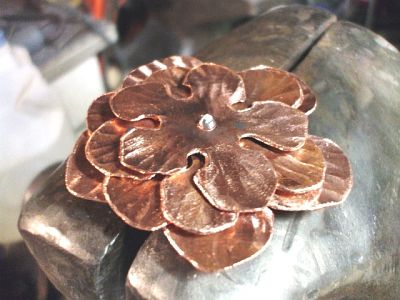
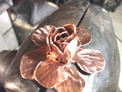
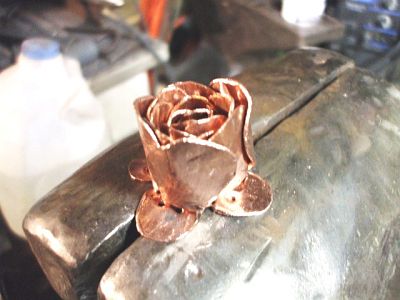
After folding the layers up into a bud, each petal is then rolled down to open up the flower form. Roll down one petal, then roll down the petal on the opposite side of the layer. This keeps it in balance.
Once the petals are rolled down and the flower is adjusted to look just right, the nail stem can be shaped as desired. Maybe curled to form a base so the flower sits upright. For this project, the stem is removed.
The remainder of the nail is ground down and all is wire brushed.
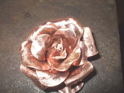
A completed rose. -
IForgeIron Blueprints
Copyright 2002 - 2011 IFORGEIRON, All rights reserved
BP0611 Choosing the steel for a Damascus blade
by Steve Sells
To begin, be aware that the process of forge welding keeps the steel at very high heat, higher than normal forging temperatures. This can cause burning of the metal, rapid grain growth, and carbon migration if you are not careful.
Various elements added to steel will effect not only how the steel performs, but also what color appears when etched in acid after the blade is finished.
Carbon = dark gray
Mn = black
Chrome = lighter gray
Nickel = silver
While many steels have many or even all of these present, the general idea is the same; it helps us to choose what metals to use for the colors we wish to present.
I begin like any other blade project, by asking myself what is this going to be used for? Like any other blade, function will effect the choice of steels used.
Dark layers: Basic 10XX series is fine for this, as is most W series. After you get experience making 100% good welds, you may wish to try the 96xx, 92xx or O series. Being good steel for knives, as well as the dark color when etched, the higher carbon is preferred, because carbon migration issues can lower this carbon level significantly . Since I know I will loose some carbon to this process, I choose my steel with that fact in mind. But you may wish to mix in medium carbon in the range of 40 to 60 for medium gray colors, or Non hardening steels like 1018 or 1005 for a very light gray to dull silver, even wrought iron can be used, but use these sparingly.
Bright layers: For strong contrast, 15N20, L-6 and 8670M are good choices. They all have about 70 points of carbon, some have a little chrome for deeper hardening, all have around 1% nickel for a bright shine. Acids do not effect the nickel bearing steels very much. And these are fairly easy to weld.
While not a beginners metal, and not good for blades by itself, Some advanced smiths use pure nickel sheet for the brightest layering, use with caution for the cutting layers, but use freely for inner sections of composite blades. Remember this is a problem to weld in a coal fire. As the sulfur causes even more problems with the pure nickel. Sometimes people choose the easy to use a203E for a brighter layer because of its near 4% nickel, and almost no carbon content.
After you get comfortable making 100% good welds with10xx series to the nickel bearing steels, you may wish to try using Chrome steels like D-2, 5160 and 52100 offer more color choices, but are difficult to weld up well.
For the truly masochistic: Stainless steels offer even more possibilities but due the the very nature of what makes them stainless, welding must be done in a oxygen free environment. I will only suggest starting to learn with D-2 and a 200 or 300 series SS to begin, before trying the 400 series or more expensive Stainless Steels. -
IForgeIron Blueprints
Copyright 2002 - 2011 IFORGEIRON, All rights reserved
BP0613 Shaping the blade
by Steve Sells
After choosing what steels to use, take it to the fire, and draw your steel into a flat bar slightly less in width than you desire for a finished blade. I use any extra length as a handle while forging, trim when finished.
Keep this at least 1/4 inches thick also. One of the biggest problems with forging a blade is getting it too thin. Or moving too much to soon. If I want a good blade I have to avoid burning my steel, and thin sections burn faster because they take heat faster.
Draw a distal taper to this bar. Just hammer the thickness to about 1/8 inch at the tip to the the full thickness when getting near the ricasso. Keeping the bar about the same width at when you started.
Then go back and start forming the shape. This is still basically a 2 dimensional bar of steel, I won't to the sides edge bevels until I get the length and shape correct. The thickness I keep helps prevent burning. When you get used to how the metal moves, you may wish to do the out side shape before the distal taper, to retain thickness, and make it less likely to “fold over” as you hammer the sides, but remember that the bar will stretch as you taper, distorting the shape, so consider this as you go.
After this is complete, I form the tang, I like to make it a little longer than needed, as cutting it off is no problem, but too short makes for trouble. Leave the tang as thick as the ricasso. Now you may start the edge bevels, I do about 4 hits on a side then flip it over and do 4 more to the other. This helps to prevent warpage in the blade. Nothing more annoying than a blade getting the cork screw effect while you work. As I form the edge bevels the blade will get wider. For reference, I will start with 1 ¾ wide stock to make a 2 ¼ inch wide double edged sword. I do not let the edges get thinner than 1/8 of an inch at this point.
So far most of this work has been done with my normal working hammer. After I get the rough bevels, I switch to a lighter hammer. This moves very little metal, but it also gives me a very smooth finish by the time I have I reduced the edges to about 1/16 of an inch.
After all of this I normalize the blade, then anneal in a box of vermiculite. Then I am off to the grinder. I start grinding with 60 grit, but use whatever you wish. After its cleaned up I switch to 120 grit, then 220 then 400. I have a tank of water near my grinder to keep the blade cool while I grind, as it will heat the metal.
After the 400 its ready to heat treat. After heat treat, 400 again to clean up anything I missed, and to remove the stains form the quench, this step is usually done by hand. -
IForgeIron Blueprints
Copyright 2002 - 2011 IFORGEIRON, All rights reserved
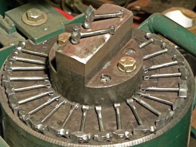
BP0662 Tapping Holes
by Digr
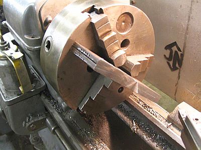
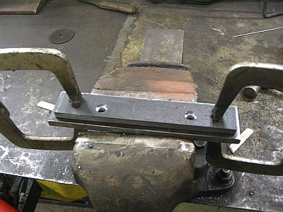
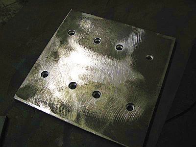

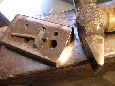
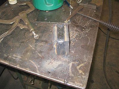
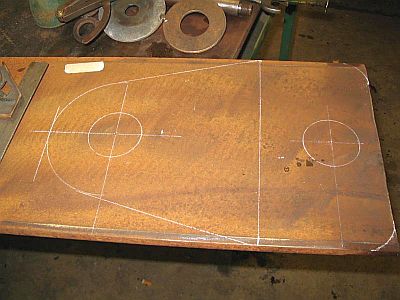
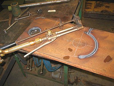
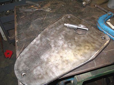
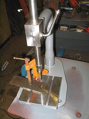
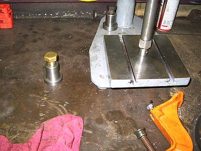
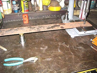
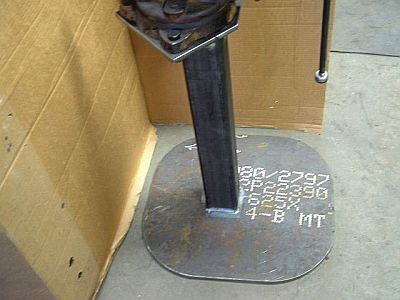
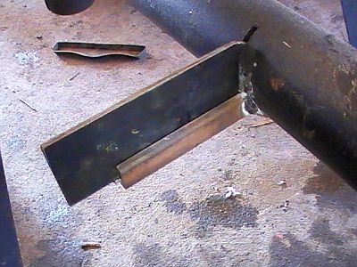
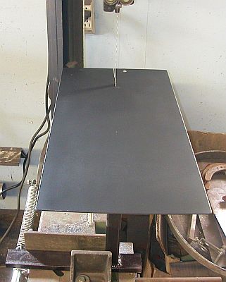
I always wanted one of these so I started one. It will take long time to finish so I thought I would put in installments. I know you can buy one for 80 dollars but what would be the challenge in that. The first step was the drawings but they changed on the way out to the shop. This post is on the table. Lots of pictures so I hope you can suffer threw them. I made a copper wedge to keep weld out of the slots when welding the sides. This is the first and only thing I have made is the table so far. The pictures were in order before the crash of 2007 but now they are not because of a little to much vodka. Thanks for looking!
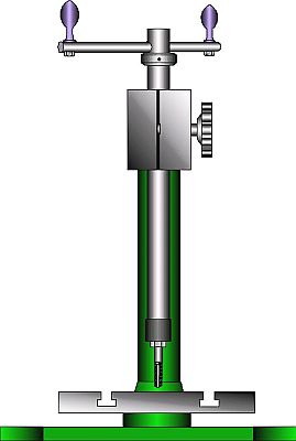
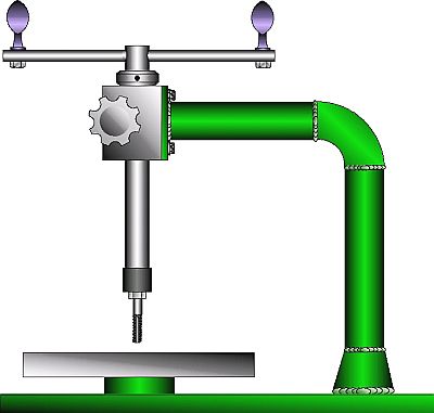
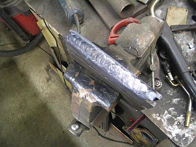
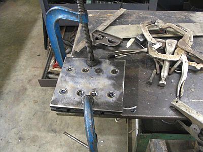
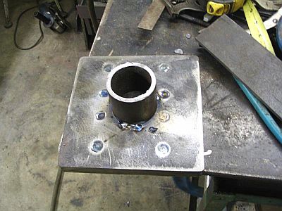
Table pics


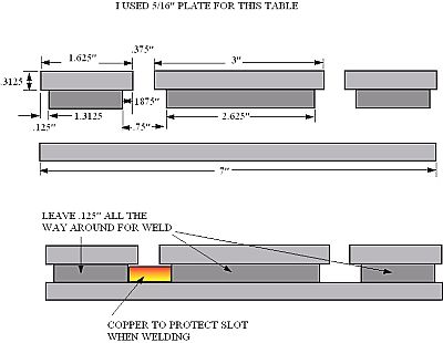
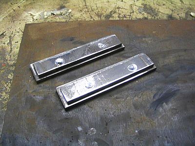
Is this what you wanted SlimJim? By no means was I this critical with the measurements but this is the measurements I was going after. I used 3/8" bolts as spacers and just spread the flat bars apart just a tad for clearance. In the pictures I allowed 1/4" all the way around but found that it was a bit much, 1/8" would be just right.

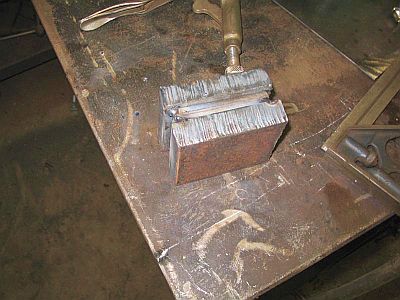
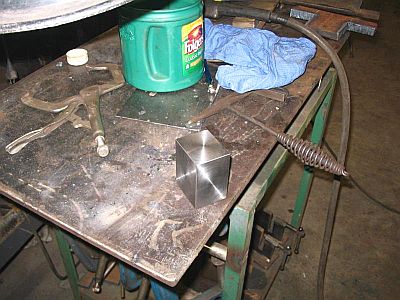
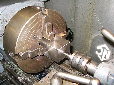
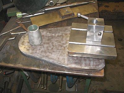
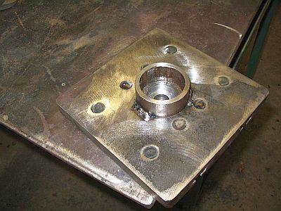
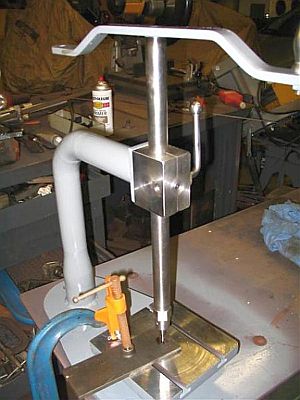
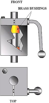
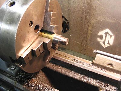
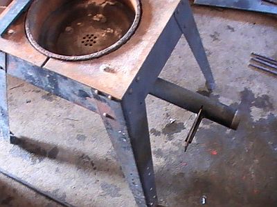
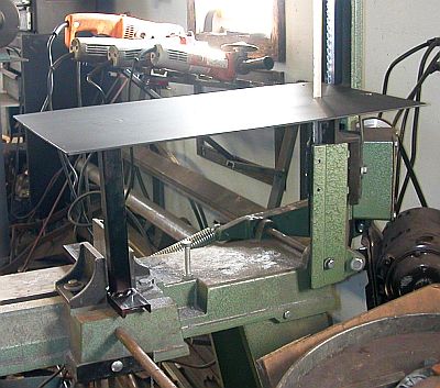
Got a little more done. Got the block and shaft done. Built up the block, drilled, bored and slit it and turned and threaded the shaft. The factory ones have brass bushings in them, mine is steel on steel but should last for years. Its not a high RPM unit and will surely out last me,
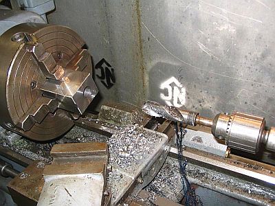
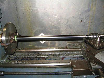
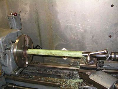
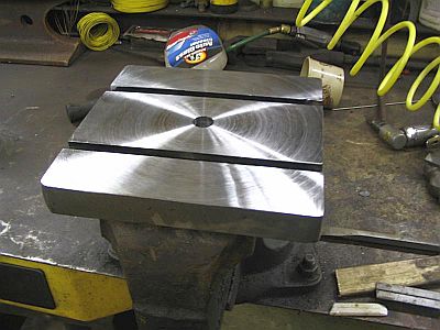
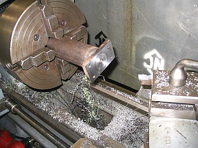
Its funny, I tacked the pipe on just so I could face off the table on the lathe but after looking at it I decided to leave the pipe on as part of the assembly
I have been looking for a small mill for home use but can't justify the cost of a vertical mill. The lathe is the most versatile machine made and you can do most anything if you give it enough thought. This tapping machine is definitely not worth the time it will take to build but when the wife says "why don't you just relax and take some time off" this is the kind of projects I like. Never could stand to sit and do nothing but I am still growing wider everyday!

I made a handle instead of the "knob" because I got lazy. I took several pictures of how I made it but I discovered that you have to have the memory card IN the camera in order to have the pictures come out.
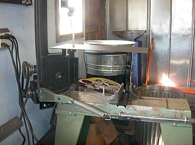
Found a piece of 1/2" X 10" flat bar that looks just right for the base.
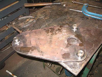
I made three legs [no rocking] for the base out of 1" cold rolled with 3/8" holes drilled in them then drilled 3/4" holes in the base for that recessed look after they were welded on. I made a adapter to align the holes.
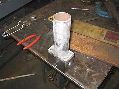
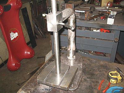
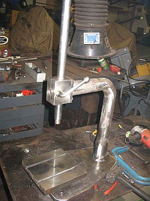
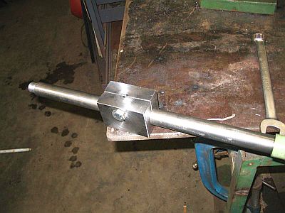
I recessed the bottom of the table so I could tighten a 3/4" nut on the shaft to hold it square well welding the arm assembly then drilled and tapped the block to accept the bracket that is welded to the pipe from the inside and faced off in the lathe.
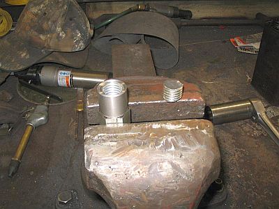
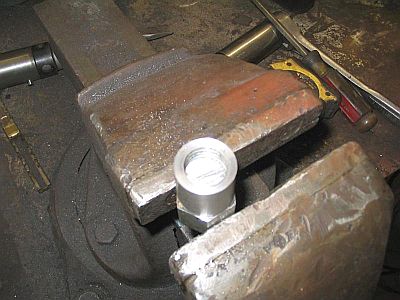
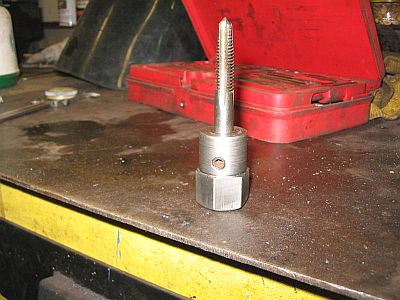
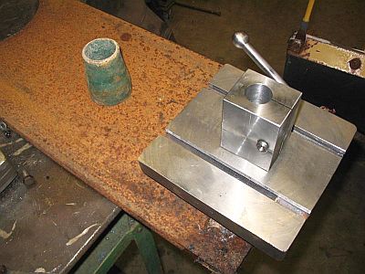
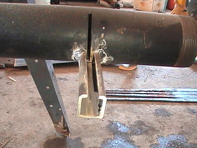
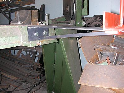
The shaft is threaded 3/4" coarse thread 3/4" long. For the tap holders I used a 3/4" coupling nut shortened it a tad and plug welded a short piece of threaded rod into the end of it making sure that there was clearance for the shaft to screw all the way on then faced and drilled for the size of the tap, in this case a 3/8" coarse tap. Added a set screw and it was good to go. I was worried about the tap holder loosing up when the tap was extracted but it was not a problem.
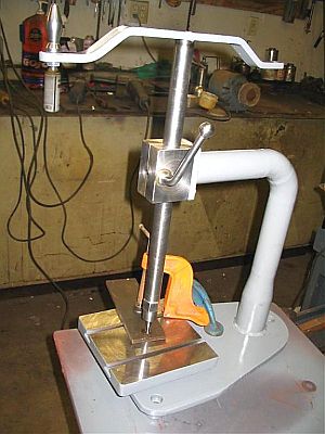
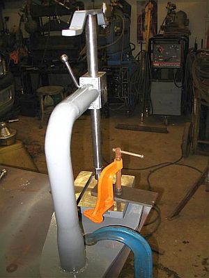
Well its done but if I had it to do again I would have made it a little different as pictured in the drawing. But it works fine the way it is. I was going to make two little handles for the top arm but one works well, I believe a second one would get caught in my sleeve when spinning the tap out. Now I have to make the rest of the tap holders. 3/4" coupling nuts are the same size as my hexagon dies so I can use tap holders in the setup I made for using dies on the lathe.
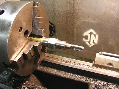
I ran into a little trouble when making the tap holders. The threads in the coupling nuts were not concentric with the O.D. I should have known that and if I had I would have chucked the up the tapper shaft before I welded the handle on it and used it to turn the tap holders. I had to thread a new shaft and use it to make the holders.
You can build this thing any size you like but I think that there would be a problem with the chuck slipping on the larger taps. You may have given me a idea, I might put a chuck on this for the smaller taps.
I think I will make a adapter for a small chuck for small taps
I thought about using those but I thought that they would be to sloppy but you say they work great I guess I should have tried them. Sure would have saved a lot of work.
I know that you are supposed to back a tap up but with a hand tapper I seldom do. You can feel if it starts to bind and back up if necessary. If every thing is straight it is seldom a problem. In the picture I was using a 5/16" tap in a blind hole and ran it all the way in with no problem. Also I would hate to put any money into this thing now. I will keep a eye out for spiral taps.
there isn't anything to stop it but it hasn't been a problem so far. I use a wrench to tighten before I start and normally the tap takes more pressure on the way in then on the way out.
-
IForgeIron Blueprints
Copyright 2002 - 2011 IFORGEIRON, All rights reserved
BP0663 Jacks
by digr
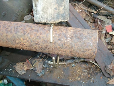
Not much happening here, I made some jacks to support long pieces on my hand tapper. I tapped them out to 3/4" coarse thread and went to my bolt bin and grabbed a couple of rusty bolts and when I wire brushed them one turned out to be brass. I went back and searched but I had only the one.
Hers another pic, they are to support longer pieces and keep them level when I tap the holes.
Yes it is rust on the cutter. That is the way it was at a rummage sale for .75 cents. I don't have a machine to put it in but I couldn't pass it up. -
BP0665 Analysis of Steel
By Richard A. (Woody) Hanson © 2007
Foreword: It’s a dreary, cold, miserable, snowy day in South Dakota. I can’t get into the shop to work and I refuse to run the snow blower again till it quits snowing. Therefore, I have decided to write yet another one of my rants. Alright, quit moaning, you know the rules, when I am bored and miserable, you suffer so cut the whining and take your lumps like a man or lady as the case may be!
Caveat Emptor: That is Latin for “Buyer Beware.” The fact that that warning was translated from Latin should tell you something. That something is “crooks have been around for a very long time.” I know you think you can spot a con man a mile away. Well a mile away he can’t do you much damage, but when he gets up close he will be in your pocket, have your money and be gone before you can blink.
Lately there have been several people who have purchased pieces of steel on EBay and then decided they need to know if what they got was what was advertised. Well DUH, you got what you got, too late to do anything about it now. Now we all know that everybody that sells on EBay are stellar individuals, just like all them guys from Nigeria who send me emails wanting me to help them get their money out of the country are really all Sons of Princes. So why worry, if they told you it was S-7 it must be S-7. I know you understand what you thought I said, I am not sure you understand what I meant. It’s sort of like a golfer who says he is “Lying 3” which means his companions did not believe Lie 1 or 2. Unfortunately S-7 to them may mean “Story 7” because nobody believed the first 6 lies.
If you believe everything sellers on EBay tell say, you will probably also be interested in the little piece of land I have down by the swamp. IT’S A BEAUTIFUL PIECE OF PROPERTY, ONE SIDE FACRS THE WATER. The top! IT HAS AN ABUNDANCE OF WILDLIFE. At least one den of water moccasins, plenty of leaches and the occasional alligator. IT ALSO HAS A SPATICULAR VIEW. In most places the water is less than eyeball deep. THIS PROPERTY ALSO HAS A COLORFUL HISTORY. Rumor has it the Mafia has been dumping bodies there for years. Ya’ll getting my drift here? People will take advantage of you and the internet allows them a degree of anonymity heretofore unimagined. Sure if you get burned on EBay you can send a message to EBay and put a “black mark” or whatever they call it against the seller. So what if the seller is using the computer at the local library, a yahoo email address and he gave EBay a phony name and address. Do you think EBay has time to check out the validity of everybody who sells there? But you have put a “black mark” against that seller and you have wounded him so grievously that he will cry all the way to the bank, but those tears are tears of laughter. Why you ask? Well I will tell you why, because at P.T. Barnum said, “There is a sucker born every minute” and to this guy’s way of thinking you took care of about an hours worth.
Example: Once I was checking into a motel in Salt Lake City, I used my credit card and the desk clerk said “I need your phone number.” I said “what for?” She said “well in case the card is stolen.” I said “if I stole the card, do you think I would be stupid enough to give you my real phone number or address?” Then I told her the number was 605-555-1212 and she wrote it down. We will not discuss the color of her hair at this time.
My neighbor lady’s Ex was a gunsmith. She was cleaning out a storage shed and came across several small pieces of steel. There are all cold finished in thickness from 1/8 inch to 1/4 inch, width from 1/2 inch to 1 inch and length about 18 inches. I accepted this steel graciously because it was clean and shiny. Hey I am a sucker for shiny things especially when offered by attractive ladies. I spark tested the stuff and it is steel, to be doubly sure I checked it with a magnet. I was thinking steel from a gunsmith, Hummmm, must be good stuff. I already had visions of the knives I would make from it. Then I took a piece of it, heated it to non magnetic and quenched it in oil. (That’s pronounced ALL if you are anywhere South of St. Louis). Alas when I tried it with a file, I found that it was just mild steel. Now I could take pictures of it, advertise it on EBay as O-1, D-2 or some other high quality knife steel and sell it for a pretty penny. If you want documentation as the type of steel, I am sure that with my computer through the magic of Print Shop or some other program, I could come up with an authentic looking certificate. It’s only useful purpose would be to help you start the fire next time you light your forge. And, what if you complain to me? I can simply say it must have been something you did in the heat treating process. As sure as my name is Dewey Cheatham that stuff is S-7 I am not responsible for what you do after you buy the steel. Hey, ya’ll quit looking at me that way, I had my shots, and I don’t get scruples or ethics. I would make a good crook if I wasn’t so honest.
By now you are probably totally lost and wondering what point I am trying to make. The truth is, I am not sure I kinda got lost myself, but we will eventually get there. TRUST ME!
Act in haste and repent at your leisure! So you bought some mystery metal on EBay that is supposed to be high quality steel. The excitement of the auction is over and now reality is setting in and you are being haunted by the question: Did I get what I paid for? Lacking a complete metallurgical laboratory, you resort to other less costly means of identification which hopefully will accomplish the same goal with the same degree of unfailing accuracy.
There used to be a guy around, who could sense the carbon content and alloy of steel my merely touching it. Handy fellow to have around, I don’t know what happened to him, I think he wandered into the “Hemp Forest” and got lost. Since the “Steel Swami” has gone missing in action, or up in smoke as the case may be, the task of analyzing steel has become considerably more complicated. However, there are a several accepted methods that are relatively inexpensive or even free that will allow you to get an idea of what you have.
Magnet: First test it with a magnet. If the magnet sticks it’s steel. If it don’t it may still be steel. Some of the grades of stainless steel are non magnetic, these are mostly the mild steels of the stainless group. 304, 308, 316.
What was it used for: If you can determine the original use of the steel, you can consult the various “junkyard steel” lists or Machinery’s Handbook and get an idea of what type of steel you have. If it was a jackhammer bit, it is probably one of the shock resistant steels, S-5, S-7. Note that I said probably. If it is just bar stock, then its primary purpose was probably to separate you from your money and it has already done that.
Get on the internet and ask a group of blacksmiths that you have never met: There is only one problem with asking a group of blacksmiths a question. You can ask 6 blacksmiths the same question and get 6 different answers and all of them are right! You don’t believe me, ask 6 blacksmiths to what color they heat steel to forge weld. To me welding temperature is a bright orange yellow that has a wet look to it, but that is just how I see it, the “actual” color may be different. For even more fun ask them to interpret the photo of a spark test you have done.
Spark Test: This is going to involve moving machinery so be careful, safety glasses at a minimum, better yet goggles or a full face shield. This involves feeding the steel into a grinder or belt sander and observing the sparks that are produced, then comparing what you saw to the sparks produced by a known sample of material. This will give you a good idea of the carbon content of the steel, and may help to determine some of the alloy components but that’s about the limit. If this sort of testing were all that accurate, the major steel manufacturers would do away with their chemists, metallurgists and analytical labs and start issuing certificates of spark test instead of certificates of analysis.
Destructive Testing: This won’t give you any indication of the type of alloy, but it will give you an idea of the carbon content. This involves heating the metal to non magnetic then quenching it. Now clamp it in the vise and try to bend it. If it breaks it is high carbon, if it bends it is not. You can also heat and quench then try to cut the metal with a file. If the file skates across the metal, it is high carbon. If it cuts the metal, it’s low carbon. How low? Who knows?
Alchemy and Witchcraft: One can resort to Crystal Balls, Ouija Boards, Tarot Cards but they are not noted for their accuracy. If you must use these methods, be careful that you do not make disparaging remarks in the presence of the practitioners least they put a curse upon you that will not only cause any future attempts at forge welding to end in dismal failures, but will also cause your horn to stick as you pull up behind a group of Hells Angles stopped at a red light.
However, if you bought some “Damascus Steel” from a company in India, this may be the best and only method of determining what you got. “Damascus Steel is comprised of 2 or more different types of steel in multiple layers. Reputable dealers in the U.S. usually use a high carbon steel like 1095 and another alloy steel containing a good deal of nickel like 15N20 or L-6. You on the other hand bought this from a country in Asia not noted for either a high degree of quality control or business ethics. What you got was what ever happened to be on the top of the scrap heap that day. Inquiring via the internet as to what the particular makeup of this steel makes about as much sense as asking the man on the corner to identify the pedigree of the alley cat that just walked by. (You knew I couldn’t write one of these without putting a cat in it someplace didn’t you.)
After word: If pedigree is important to what you are doing, buy virgin steel from a reputable U.S. dealer and ask for a certificate of analysis with it. If you are going to use “junkyard steel” do your own dumpster diving and pick easily identifiable known items, coil spring, leaf springs, jackhammer bits etc. I make knives from recycled steel and all of them come with my 50/50 guarantee. If one breaks from a defect in workmanship or material, return it to me and I will throw away both pieces oh and I will refund the full purchase price or replace the broken knife at your discretion. If on the other hand the knife was broken by abuse, I will inform you that you have just learned a very expensive lesson. That lesson is do not use a piece of cutlery for a crow bar. -
IForgeIron Blueprints
Copyright 2002 - 2011 IFORGEIRON, All rights reserved
BP0668 Making Thorns
by goatman
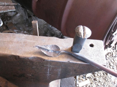
I’ve been trying some “Russian roses.” I have two done so far and plan to do another one or two tonight. I’m not thrilled with the result of the flower head, but I am proud of the fact that I learned to make thorns on the stem. Isn’t that the way relationships are? The thorns come easy; you have to work on the flower.
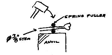
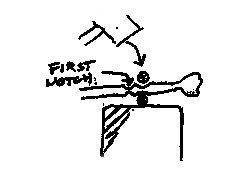
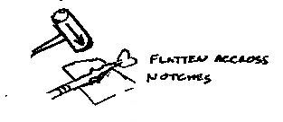
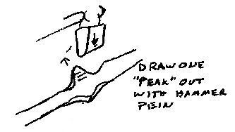
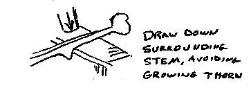
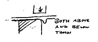
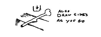
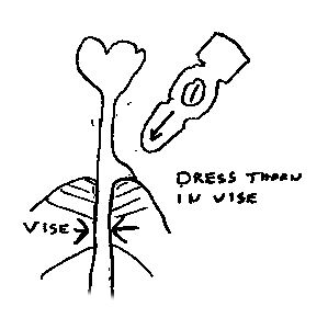
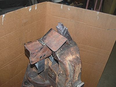
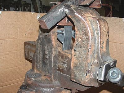
I make the rose head first, from 3/8” dia. round. Then draw the stem down just below the rose head, leaving the full diameter below about 2”. I heat this and use my spring fuller to make two notches next to each other, as shown. I turn the piece 90 deg., and start flattening the fullered area. This pushes the “peaks” between the notches out. I draw one peek out further with the hammer pein, alternating between doing this and drawing and flattening the surrounding areas down, also hammering on the sides of the stem, with the thorn laying across the anvil face. Finally I clamp the stem in the vice and draw the thorn towards the base of the stem. My old worn vise gives a nice inside radius, and dressing the thorn down away from the flower head gives it the look of a hooked thorn. -
IForgeIron Blueprints
Copyright 2002 - 2011 IFORGEIRON, All rights reserved
BP0669 Carving Block
by Mike-hr
Mark-B set me up with this monster old Chas. Parker vise. (Thanks again, Mark!) It has tall jaws with recesses built in for accepting vee-jaws for gripping round stock. I used this void to make a fixture for holding the carving block steady whilst making animal heads. It seems like I always waste the first few seconds of fresh heat fumbling to get the carving block in the right place to tighten the vise. I like using 2 x 3 inch angle iron to make the carving block, so I can get 2 different attack angles to the work. That's why the block has two different bushings, one for each side. Being pinned in, the block stays where it's supposed to,works great, and changes position in seconds.
Another thing that came out real good is the base plate. (5/8 x 24 x 24 inch). I had the waterjet guy cut 8 inch radius' on the corners so I can roll the set up around the shop. I also had him cut a square hole so the 4 inch upright tubing fits inside. I shimmed it 1/4 inch above flush on the bottom and tack welded the corners on the top once it was fair and plumb. I did all the heavy stick welding from the underside, and the weld-warp made the plate cup slightly down, instead of cupping up if I had welded from the top.. The result is, the vise sits along the outer edge of the plate, and is less affected by scale and bits on the floor, minimizing the wobbling that can accompany a portable base. The other good thing about this vise is I can place it just off the forge, but where I can walk all the way around it unencumbered to do the same chiseling from each side.
the angle iron is 2 x 3 x 3/16 US inches. It doesn't matter what it is if it holds up to your whacking schedule. -
IForgeIron Blueprints
Copyright 2002 - 2011 IFORGEIRON, All rights reserved
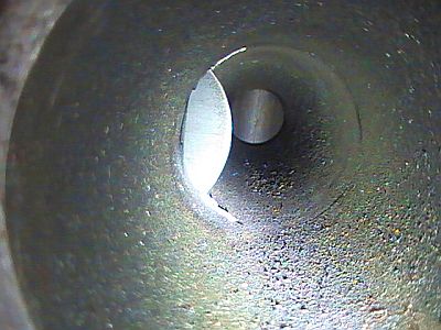
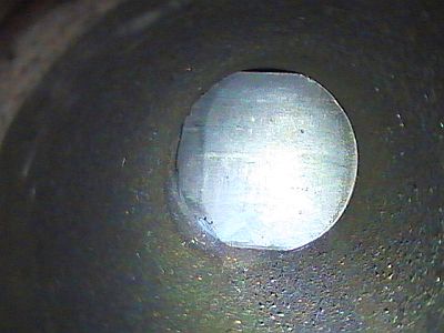
BP0670 Gate Valve for the Forge
by Adam Durham aka Tech 413
I made a sliding gate valve by cutting a slot in some 2" scet. 40 pipe and making a 1/8" plate to fit. I'll get some pics later today. hope it helps.

-
IForgeIron Blueprints
Copyright 2002 - 2011 IFORGEIRON, All rights reserved
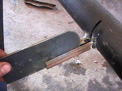
BP0671 Harbor Freight Saw Modifications
by Ralph and Jeff Phillips
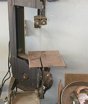
It clamps in the vice, and mine I made one of the other table screws fit for stability.
The first is a table for free hand sawing, my Dad had one and I copied it. So I can't take full credit for it, just my version. The one that comes with it has the slot in front, which makes sawing small stock out of the question.
The table is 12 gauge, 10 x 16 inches, with a slit in the back for the blade, I made the slit with a cutter wheel on a 4" grinder. I used a piece of heavy flat bar to get the cut nice and straight.
For the bottom piece I used 1 1/2 channel, and welded a piece of 1 inch square tube for the upright. I left the upright over length, and clamped it in the vice and used a square to determine how high it should be, and cut it off.
Then I clamped it up in the saw and marked the back screw hole, mine was a quarter inch hole, and I countersunk the top. I painted it with multple coats of flat black, so I could mark on it with soapstone. You could also clamp a piece on angle iron to use for a saw "fence". SAFETY: Always use a push block when sawing near the blade, the blades on these leave a nasty jagged cut.
I put the table on and marked where the upright rested and tacked and checked it, had to take 2 tries to get it right.
This mod is a table for the "outfeed" side of the saw with a quicker stop.
The table is 4 inches by 16 starting size. I drilled two holes 3/8 holes in the end of the plate by eye, then drilled and tapped the end to the saw for 5/16 bolts. Place these holes carefully, the casting for the old stop is pretty big on the back, stay away from it.
I then slit the plate far enough through to bend it to the angle that made the table on the level with the existing table, this took some trial and error, but I left enough material so it bent pretty hard, but right on the cut. I then ran a mig bead up the outside of the angle, and ground it off flush.
I then added the stiffener rod 3/8 square up the center.
I used my vice to create the offset pieces for the underside, and clamped and moved them until it fit snug, but slid with little effort. I then welded them 100%. You can also use a vice grips to keep the outbound end stable and keep it from hitting the floor....
For the clamp I used a piece of angle iron, drilled a hole and welded a nut, and the "T" handle on a bolt, I used a 3/8 bolt.
I only use the stop on occasion, like when I have 5 or more of something to cut, otherwise I measure, mark and cut the first, and use it to gauge the other couple of pieces.
The biggest problem I had with the stop that came on the saw is it was in the way, and you had to have a wrench to move it and one hand to hold it, then tighten the other with a wrench. I only have 2 hands and end up balancing the tape measure, set it, check it, move it again, use the fine adjustment. I added a longer rod to mine, and the setscrew kept cominig loose. This stop is slide on and slide off, with a T-handle hold down. The other thing is with irregular shaped stuff, you slide the stop off the end, and you can tong to the table with vice grips, which for long stock, it keeps it from falling on the floor when the cut goes through. I had that "Ping Ping Ping" when stock hits the floor when I am trying to do something else.
-
IForgeIron Blueprints
Copyright 2002 - 2011 IFORGEIRON, All rights reserved
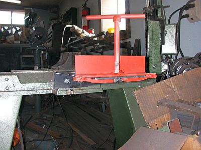
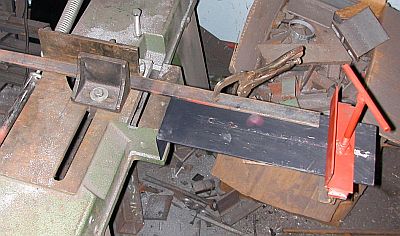
BP0673 Double-Bick Anvil Holddown
by Mike-hrHere's some pics of my double-bick Peddinhaus anvil. I've been questing for some time to come up with a good hold down. I made several hairpin-spring pritchel hold downs, but the pritchel hole is situated too far forward to have much room left to work once the hot piece is dogged down.

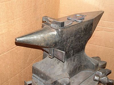
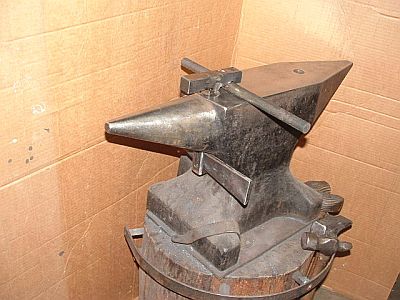
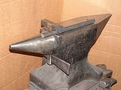
I made this low profile tee-shape hold down from two pieces of 1 inch square and a chunk of lea fspring from a '58 Chevy hay truck. The leaf spring was 2-1/4 inch wide and 3/8 inch thick. It determined the dimensions of the slots for the hardy post. I milled slots on both axis, so the hold down will grab North-South, or East-West (Mcraigl thought up that idea). I forged a Vee in one side of the top piece to hold round stock. With a quick couple taps on the key, it holds work down super tight. The low profile is easy to work around, and the tool doubles as a faux-step when needed. The pressure releases instantly with a tap on the small end of the key.
BP0787 Attaching small flowers
in BP 700 Series
Posted
Posted 04 September 2011 - 02:28 AM
 beth, on 04 September 2011 - 11:46 AM, said:
IForgeIron.com Blueprints
Copyright © 2002 - 2011 IFORGEIRON.COM, All rights reserved.
BP0787 Attaching small flowers
by John B
Posted September 4, 2011, 06:00 PM
Quote
Minotaur, on 03 September 2011 - 02:14 PM, said:
Quite a scrap pile! Would you happen to have a photo showing how the small flowers are attached to the scrolls, like in the picture below?
Quick answer on that I am afraid is no, I'll try to remember to take some next time I have a rummage, but I don't know when that will be.
I will try to explain the way this was done in this specific item.
http://iforgeiron.com/content/blueprints/700/787/01.jpg
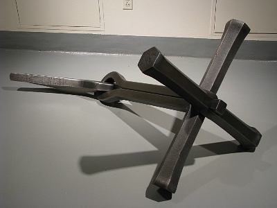
The flower itself consists of two pieces; the fluted outer, and the domed inner.
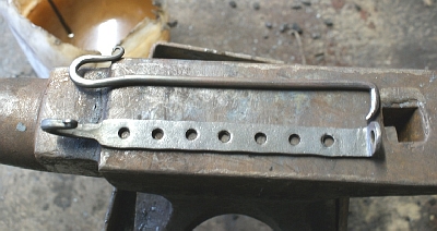
The whole is attached to what I would describe as a loop in the end of the scroll, similar to a rolled penny snub end, but with a hollow centre or a bolt end scroll with no bolt.
The domed inner is a textured rivet head. The stem of the rivet is passed through the eye in the scroll end, a washer or rove is placed over the protruding rivet stem, and the item is then rivetted on. (In certain areas, these outers actually spin on the rivet.)
These old pieces are quite intriguing in how they were assembled to form the shapes you see. They are all straightforward and simple. We tend to look for more complicated methods than what were actually used; just basic simple blacksmithing, screws, nuts (of different shapes and proportions), studs, rivets, and brazing.
What is noticably missing in these examples are collars, probably capitalising on the latest technology of (relatively) easily available machine made taps and dies of a standard form, thus rendering collaring to join pieces not essential.
http://iforgeiron.com/content/blueprints/700/787/02.jpg
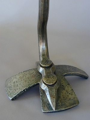
This particular one shown here is a great example of what I mean. If you or others are interested in its make up/construction, I can post pictures, so you can see how it is constructed, or maybe even start a new thread for it.
Anyway, I hope the explanation clarifies your enquiry
Happy forging!
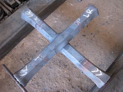
Here we go Minotaur, and all other interested parties. This should clarify what is involved in the ornamentation discussed.
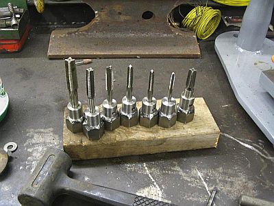
First the entire piece prior to being mounted to another part,
http://iforgeiron.com/content/blueprints/700/787/03.jpg
http://iforgeiron.com/content/blueprints/700/787/04.jpg
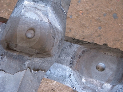
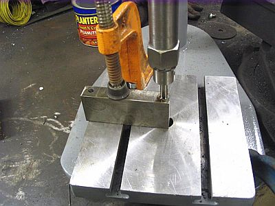
and the end view of the ornament mounting.
http://iforgeiron.com/content/blueprints/700/787/05.jpg
http://iforgeiron.com/content/blueprints/700/787/06.jpg
http://iforgeiron.com/content/blueprints/700/787/07.jpg
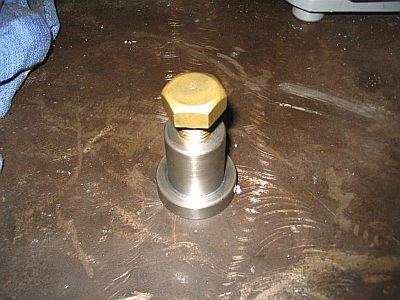
The actual disc and centre to be mounted, (the centre is a textured dome head rivet.)
http://iforgeiron.com/content/blueprints/700/787/08.jpg
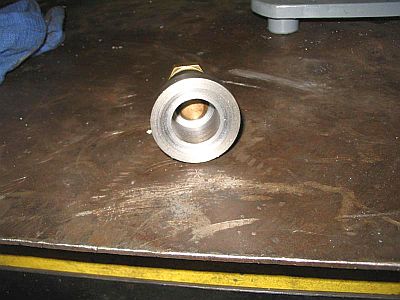
All the pieces involved: disc, domed head rivet with textured head, domed rove for the rivet, and the end of the scroll assembly it fits to.
http://iforgeiron.com/content/blueprints/700/787/09.jpg
http://iforgeiron.com/content/blueprints/700/787/10.jpg
Thanks john! Thats a great piece of ornament or whatever you would call it - really like the flower - its like a brioche bread pan. I like that its made from one piece. What would be the best way to make such a lovely fat large domed rivet?
However which way you favour, I would probably start with a diameter bar approximately 1/2-plus of the finished diameter required. Form a tenon of the required diameter on the end, as long as is required to pass through the components and attachment parts, plus a rivetting allowance to secure the rove with. Finish with a swage to produce an accurate shank.
Cut the piece off of the end of the bar, leaving enough material to make the head dome you require. You may have to guesstimate this for the first one. Note that size, so you can adjust for later ones if necessary.
Make yourself a rivet snap tool of the desired profile.
Then use a rivet header/bolster to produce the domed head. (You can also use this tool to produce the domed roves.) Make sure the bolster has a slight chamfer on the top of the hole, as a sharp corner under the rivet head is generally regarded as undesirable and can lead to failures. (It probably would not on this size, but it is good working practice.) I would heat the bar to do this, just like making nails, except you are die forming the head with the snap.
You then have the texturing to think of.
In this situation, my plan would be to rivet the assembly together first. (Don't forget to chamfer the centre hole in the rove to allow for rivetting.)
Then using a domed bolster under the roved head (you could use the snap you had for forming the rove and domed rivet head) as an anvil, apply the texturing you desire. This will also planish the rove sides, and increase the strength of the rivetting.
If you pre-form the texturing before rivetting on the rove, you run the risk of deforming the texture you have applied to the rivet head.