

Steve Sells
-
Posts
9,163 -
Joined
-
Last visited
Content Type
Profiles
Forums
Articles
Gallery
Downloads
Events
Posts posted by Steve Sells
-
-
IForgeIron Blueprints
Copyright 2002 - 2011 IFORGEIRON, All rights reserved
BP0312 Making a Cut-Off Hardy
by Mike-Hr and McraigL

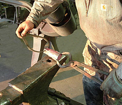
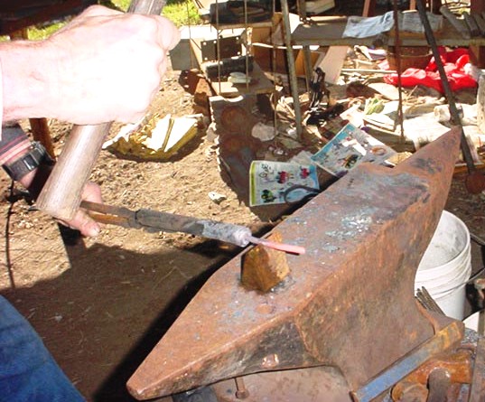
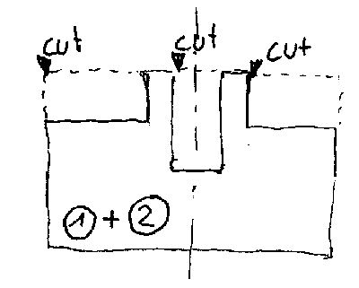
McraigL (Mike) just bought a 204# Peter Wright with a 1 inch hardy hole and needs a cut-off tool. We cut this axle as shown, we'll make the tool from the middle section.

We heated the tongs up and adjusted them to fit the piece. The first move is to pull a tenon that fits the hardy hole. It's very difficult to grip the wedged side of a hardy tool.
Using calipers to check size.

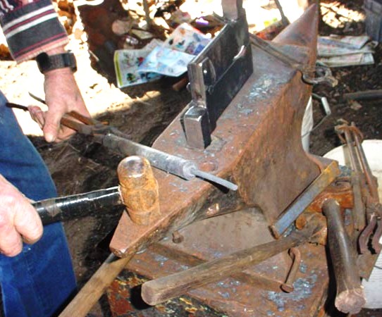
It fits in the hardy hole, Mike's giving it a few taps to seat the piece. It's really convenient if all your friends have the same size hardy hole. Mike can come to my shop and make stuff to fit his anvil, and not have to drag it along.

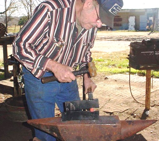
We changed tongs to fit the 1 inch square tenon, and started the wedge with an incline die.
It's almost there. We thought it over and decided to orient the cutting edge 45 degrees from square, for more comfortable working on the anvil.

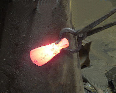
We used a handled chisel to cut off the swell on the end. The bevel left by the chisel also helped establish the finish grinding angle. We used the remnant on the end to perform tests for junkyard heat treating. The little chunk didn't harden in oil, but did great in water. We normalized 3 times, then heated the whole piece to non-magnetic, and did a feathering quench of the leading 3/4 inch in water, filed a shiny line, and used the residual heat in the body to run the temper to a brown/blue. When the color got to the cutting edge, quench the edge for 1 second, file a new shiny line, and let the colors run again. We continued this process until the piece ran out of heat to temper with. Some folks call this process 'triple drawing'.

Mike ground the edge to a one sided 'butcher' face, and we got a real nice cut on some 3/4 inch square with it. -
IForgeIron Blueprints
Copyright 2002 - 2011 IFORGEIRON, All rights reserved
BP0399 Clamps
by Mr. Smith of Oz
Grab yourself a bolt, a nut to fit, and some tube. Square tube, pipe, rectangular tube – it’s all good. Whatever type of tube you use, you’ll need 30mm-50mm or thereabouts. A length of threaded rod would also be good in place of a bolt. Drill a hole in the tube. Make the hole a bit smaller than the nut, but bigger than the bolt or rod. Weld the nut over the hole. Be careful not to blow a hole in the tube wall!! Thread in the bolt or the threaded rod. Hey presto! A clamp! Use them to hold saw blades together when making Damascus, or what have you. Some uses for easy to make clamps.


Holding hacksaw blades together when making damascus when making damascus, or Mokume-Gane.

Holding round bar together (weld the bottom two together first) I'm sure there's other uses folks can come up with!

-
IForgeIron Blueprints
Copyright 2002 - 2011 IFORGEIRON, All rights reserved
BP0397 Chili Pepper
by Bill Epps

The fullering tool I used.

A short piece of 1/2 pipe sch 40.

The fullering tool fits into the hardie hole of the anvil.

Starting the set down (hitting on two sides hit rotate 90 deg hit making it square before I make the hole round).
Making the hole back round.

Hole is round ready for the stem (which I make from 1/4 round).

Setting it down around the stem.

Stem locked into the pipe.

Now I set down the the top part (what ever it is called).
The top is made.
Cut off the excess.

Draw out the stem.

Drawn out stem.
Curling the stem over the horn.
Finished stem.
Now I start the forming end of the pepper.
Now it is starting to look like a HOT pepper.
Another view.
Pinching off the end.

Clean up with wire wheel (cup wire wheel on a low rpm sander polisher NOT a high rpm angle grinder )

Finished chili pepper.
-
IForgeIron Blueprints
Copyright 2002 - 2011 IFORGEIRON, All rights reserved
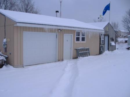
BP0396 Shop Storage
by Richard Thibeau
When finally the point is reached that one is allowed to have a separate shop to work in, a building is erected to house all the toys...er, that is, the necessary tools and equipment.
This is only the beginning of an ongoing dilemma. The shop building is never large enough to easily house everything that is dragged home, that is to say to adequately store the necessary tools, equipment, and materials needed. It is not long before piles of stuff begin to grow.

The shop interior can become cluttered looking to the untrained spousal eye.

As a self preservation matter, some means of organizing has to be implemented to move important items out of the way when not being actively utilized.

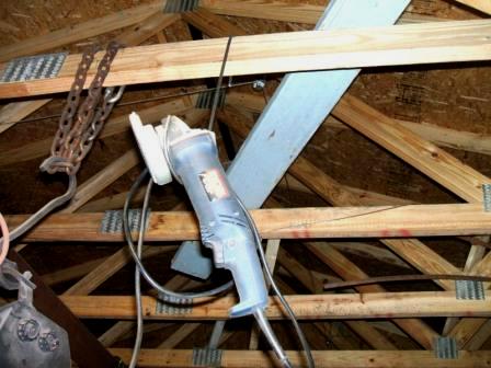
Small tools are commonly left wherever they were set down last which often is not where one looks for them later. Electric tools also have dangling cords that become unruly. A beginning only, but hanging tools in easily accessible locations, such as under the edge of the bench, is a habit to encourage.

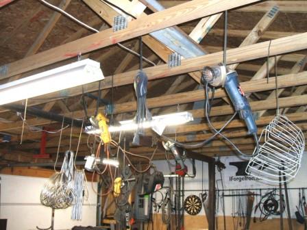
Other handy locations are right over head in a lot of instances. Up out of the way, but still within easy reach.
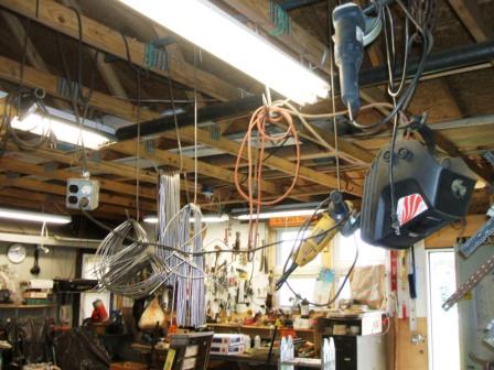
Empty air is a fine storage location when properly utilized. Make hooks of the size to fit whatever item is being hung up and of the length necessary to be above head level (walls are for banging heads against, not tools) yet still within easy reach. The hooks are placed over the rafters, joists, trusses, whatever is there.
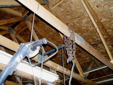
A length of pipe can be laid across the rafters to provide a place for hooks if there is need to have a hook in a certain place.
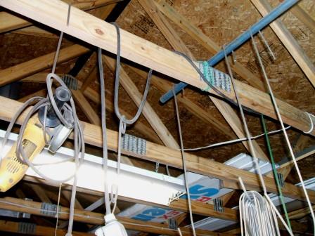
Hooks can be used to store hooks as well. Things are starting to look up.

-
IForgeIron Blueprints
Copyright 2002 - 2011 IFORGEIRON, All rights reserved
BP0395 Easy Punches
by sfDuck
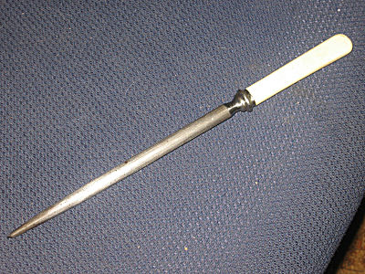
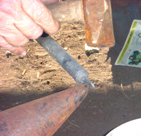
I just happened to have a few butchers steels hanging around and suddenly the light bulb turned on.

They were cast steel, hardened and able to sharpen stainless. If you removed the handles and tangs they would make nice extra long punches. That Easy. Rework the ends and they could become any shape you could imagine. And can pick more up cheap at the local flea market.
-
IForgeIron Blueprints
Copyright 2002 - 2011 IFORGEIRON, All rights reserved
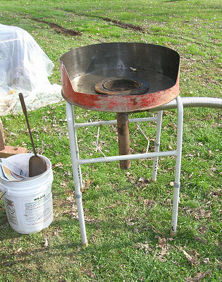
BP0394 Side Draft Forge
by Richard ThibeauAt the Dancing Frog Forge, coal is burned in a side draft forge. The construction is fairly simple as the base of the forge is stacked concrete block with a 4’x 4’ SS diamond plate sheet as the table. The chimney is 10 inch diameter stovepipe sitting in chimney block and resting on the table top. The stovepipe goes up to a commercial metal chimney. No mortar was used on the block, it is stable because of its own weight. The firepot is from Centaur Forge.
 At the bottom of the stovepipe, a “T” connector was cut out in an arch for the opening facing the firepot.
 My favorite method of starting the fire is by using a shovel full of coals from the wood stove. It’s simple, quick, and very efficient. During cooler weather (most of the year around here) the wood stove is the first thing to get going, so there is a ready supply of coals.
 A little air added to the coals from the wood stove gets them ready for the coal.
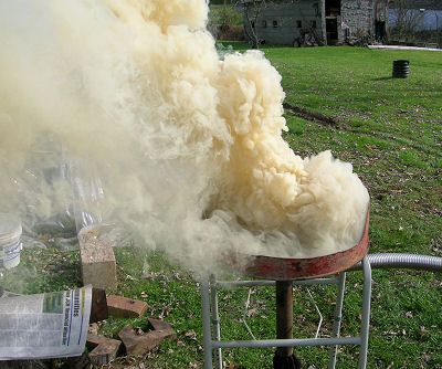
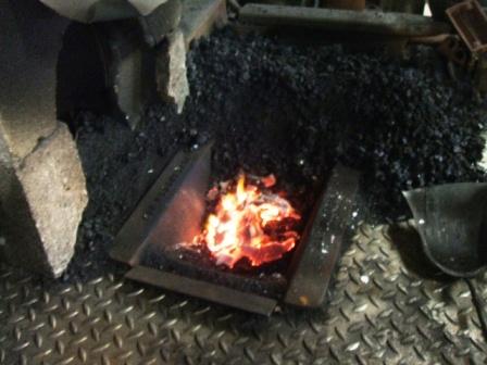 The coal is raked onto the wood coals and a little more air is added. The coal has coke mixed in from the last time the forge was used and catches quite readily. Notice how the flame is being drawn into the side draft of the chimney.
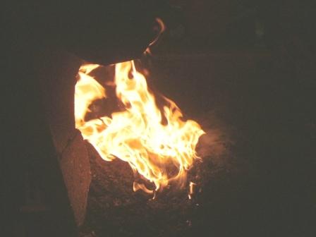 More fresh coal is added and the amount of smoke increases, but it is being sucked out and up the chimney. To make this happen easier, either start with a small fire and gradually build it up, or preheat the chimney by placing burning paper or coals from the wood stove inside to start the updraft.
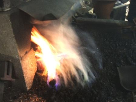 The fire is now well established and ready for forge work. The more the air is cranked up, the higher the flames go, and the more draft will be produced to suck the flame, smoke, and heat up the chimney. Fresh coal is piled up along the perimeter of the fire and watered to start the coking process. It will be raked into the middle to maintain the fire as work progresses. There will be little, if any, smoke at this stage.
 At the end of the forging session, the firepot is shoveled out and the coal fire allowed to die out. The coke can be saved separately or left to be used in starting the next fire. In this session, two hammer heads were heated for tempering and no clinkers were formed. The forge is left as is, ready for the next fire to be made.
-
IForgeIron Blueprints Copyright 2002 - 2011 IFORGEIRON, All rights reserved BP0393 Long cut on a lathe by Irnsrgn
This is a small line up tool, I borrowed from an old time RR machinist that makes things simple, and it will work in any lathe.
One of the hardest things to do is to make a long cut on a lathe and not have it tapered. A lot of people don't realize you have to zero your tail stock in some fashion. This can be a real pain, as you take a small cut, mic the ends of the cut and attempt to compensate by adjusting the tail stock, another small cut to check the alignment, it gets time consuming and frustrating.


1. Drill the center hole in the stock to be turned.2. Set the stock up in your lathe and adjust the tail stock to the proper position. 3. Remove the stock, put the line up tool in the lathe and check or reset the tail stock with a dial indicator and you are ready to go, checking the results is a good idea after the first cut. a. To make this tool, you will need a piece of scrap round stock, a full length 1/4 inch or so brazing rod and a spring that will slide over the rod. b. Machine the stub to any size desired, drill a deep center hole in the end, bore and tap a 1/4 threaded hole in the end. c. Leaving the stock in the chuck, under size a section next to the chuck so that you leave a shoulder. d. Part the end off and chamfer the edges. e. Thread the very end of the bronze rod and screw it into the end piece leaving enough room so the tail stock point doesn't bottom out. f. Make a stop collar with a set screw to tension the spring.
-
IForgeIron Blueprints Copyright 2002 - 2011 IFORGEIRON, All rights reserved BP0392 Log Hooks, J Hooks, and Log Dogs by Glenn Conner
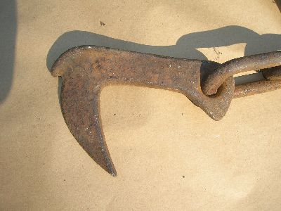
This is a device used to attach a chain to a log, I have heard it called a log hook, J hook, and log dog. To use the tool, just hammer the point into the side of the log, hook onto the chain and pull.
This is one of the early projects I made. At that time 3/8" x 1" bar stock looked like it would be heavy enough for the task. The stock was cut at an angle and welded to another piece of stock. Chain was welded to the end of the piece. Notice that there is only one hook. This is so you can drive the dogs into the side of the log and then adjust the loop of the chain as needed.
These dogs have done a lot of work and yes the top one is bent a little from the stress of pulling.

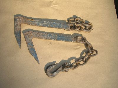
This set of dogs was found at the flea market and I grabbed them for the hooks.
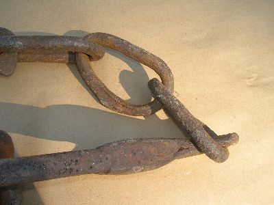
Then I realized that the chain was not real smooth, and was not real oval shaped. Then there was that thick piece that looked like 3 pieces welded together.

From the side you can see the overlap and forge weld.

And this shows it even a bit better.
This piece of equipment was used to connect two logs together during the pull. A second team of horses was then attached to the center hook to assist in the pull. This open hook allowed the horses to pull but if the logs ran faster than the horses, would disconnect and not run over the team, or drag them down the hill.
It was interesting to find the chain was hand made and forge welded as well at the center link forge welded. I just picked it up from the table at the flea market, paid the man and walked away with a blacksmithing treasure.

2# blacksmithing hammer for size.

Oil can for size.

3 photos to give you some relationship of size. Hands differ in size so I included a 2# blacksmithing hammer and an oil container.
-
IForgeIron Blueprints
Copyright 2002 - 2011 IFORGEIRON, All rights reserved
BP0391 Tenon Tool
by Bill Epps

I start with 2 pieces of 1 inch sq 6 inches long.

Drill holes that are 1/4, 5/16, 3/8, 1/2, 3/4, and 1 inch in diameter.

Using the angel grinder, I relive the edges, round them over a bit..

Edges after grinding.

Using a piece of 1/2 inch round bar 36 inches long, I make the spring.
After flatting the center section (about 10 inches long ) bend the center in a loop. Weld the spring to on one end of the tenon tool.

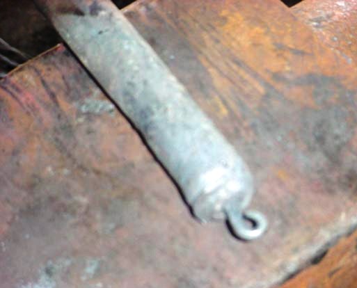
The finished tool.

Tenon made with new tool.
-
IForgeIron Blueprints Copyright 2002 - 2011 IFORGEIRON,
All rights reserved
BP0390 First Fire at the Forge by Keykeeper

So, I've got the forge built now. Some may recognize the design - the famous 55 Forge of BP0133 fame (see this blueprint for all the particulars). With my budget restraints, this is my best option at this time. Join me as the first fire is lit in it.

Close up of the firepot and grate. Just an old single disk brake rotor. The lug bolt holes were filled in with weld, but just dropping a bolt into the holes will work. An old bolt was welded in to serve as a grate.
Here's a shot of the forge's support structure. You can also see the air tube and ash drop--scavenged 2 inch pipe welded into a tee. That's right all you eagle-eyed viewers--the legs are a potty chair frame which is easily adjustable for height. I'll bet my Grandma's smiling down at me right now. She never did like that thing.

Watch the edges where the pan was cut out using a jig saw. They are VERY sharp, and need to be made safe using whatever method works best for you. I'll take care of that later, for now, lets get back to this fire. Let's start the fire up. Here we balled up some old newsprint and lit it. You can use sticks from the yard or torn cardboard or what ever works for you.

Lets add some air from my air source. Scavenged squirrel cage blower from an old wood heater and scavenged piece of flexible stainless 2 inch hose. Total cost for these pieces?..... NADA, ZIP, ZILCH...My brother is a junk-man!!

Add a little fuel (in this case, coal fines) on top of the burning paper. This whole forging session was done using just coal fines.

Let's give it some more air, just to get it going good.
A little more fuel and more air and you get a little more smoke, but only at start up!

A couple minutes later. Note the decrease in smoke and the bed of coals in the firepot. I think that's what we are aiming for.

After a couple minutes more, were almost ready to forge with it. I cut the air blast down a bit. Other than lighting the paper and adjusting the air, there was nothing done to the fire to this point. No poking, no fixing, nothing, I just stood there and watched.

The fire is now ready to be used for forging. We went from dead cold to forge welding heat in just a few minutes time.

Another view of the forge, ready to go. Note how little smoke there is at this point. Also, note how the whole setup can be broken down for storage or transport.

There has been some talk of late about anvil stands. Here's mine, with my 70 pound anvil in place. Work's fine for me!
This was made using the previous viewed fire and anvil. Not bad for a beginner! Besides making something for the wife can never hurt.

Here's a shot of my whole setup. Everything can be moved inside to the shed at left when I'm finished with a forging session. It's low tech and portable, gets the job done, and didn't cost much at all. In fact, a few dollars (for coal) will put YOU in the driver's seat. All it takes is a little investment of your time and some creative scrounging.
I used regular coal (lumps the size of a ping pong ball) the next day, and it lit right up using the same process as above.
It is easy to say "JUST DO IT!" but it would be better to say "JUST GET STARTED!"
-
IForgeIron Blueprints
Copyright 2002 - 2011 IFORGEIRON, All rights reserved
BP0389 Tool Holder
by Keykeeper
Too many tools that you can never find when you need them?

This happens to be the adjustment on the front of a plow. Attach to the wall and insert screw drivers.
-
IForgeIron Blueprints
Copyright 2002 - 2011 IFORGEIRON, All rights reserved
BP0388 Dressing Tools
by Glenn Conner

Your standard wood splitting wedge that was used last season.

The top is mushroomed some from use.

This side shows a bit of a curl to the metal.

And this side shows cracks that could become shrapnel if it were to chip off.

Another wedge that needs attention.

The edge is musshroomed a little, This would be a good time to bring this back up to usable condition.

It is just a matter of grinding off the edges and putting a radius between the side and face so there are no sharp edges. These are good to go for another season.
-
IForgeIron Blueprints
Copyright 2002 - 2011 IFORGEIRON, All rights reserved
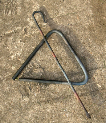
BP0386 Bending 90 Degrees
by Irnsrgn
Just a short piece of scrap angle iron the width of the vise jaws.

The Angle jig and a piece of 1/8 by 1 flat marked and clamped in the vise jaws.

Bent cold and hammered flat, nice sharp bend just where its supposed to be, also works hot for thicker material. -
IForgeIron Blueprints
Copyright 2002 - 2011 IFORGEIRON, All rights reserved
BP0385 Anvil Hold Down
by Keykeeper

This anvil is 70 pounds. A small anvil has a lot of advantages. Small in size so it fits small work perfectly. Easy to move or carry.

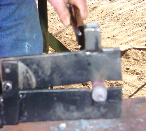
And when you go to the hardware store and find a hold down clamp for the drill press, it fits perfectly into the prichel hole of that "small" anvil".
It can be modified to fit any anvil. Just replaced the shank on the hold down clamp so it would fit the pritchel hole.
-
IForgeIron Blueprints Copyright 2002 - 2011 IFORGEIRON, All rights reserved BP0382 Offset Bend 2
by Irnsrgn

Many people have trouble making an offset bend on the end of a piece. Make the second bend, the one farthest from the end first.

Straighten up both sides of the bend before doing the second bend.

Localize up to the first bend and then make the second bend and straighten up to your specifics.

What the finished offset looks like, its quick and easy this way and not fighting with undoing the bend nearest the end when making the second bend. -
IForgeIron Blueprints
Copyright 2002 - 2011 IFORGEIRON, All rights reserved
BP0381 Offset Bending 1
by Irnsrgn
Short scraps of 1 inch wide material about 3.5 inches long with a 90 bent on one end, l to r - 1/8, 3/16, 1/4, 5/16 and 3/8 inches thick.
Set up in vise jaws to put a 3/16 offset in a piece of 1/8 by 1 cold.
The result of the squeeze.

The offset by itself.
offset bend 1 05 - The bend can be made much closer if done hot. -
IForgeIron Blueprints
Copyright 2002 - 2011 IFORGEIRON, All rights reserved
BP0379 Consumables
by Glenn Conner
Consumables - able or meant to be consumed.

It is unwise to try to get the last little bit of use from a consumable product. This wheel was doing little work but was throwing wires everywhere. You can see where the locking nut was in contact with the material being wire brushed.
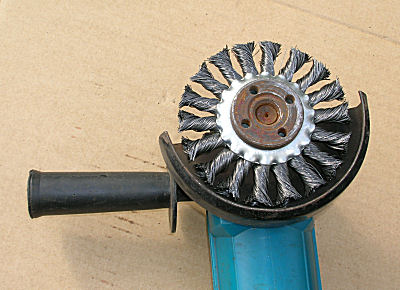
The replacement wheel shows just now worn the old wheel had become.

The replacement wheel even looks large by comparison.

The same is true of grinding wheels. When they get small the surface speed slows down and they don't work as well.

The new grinding wheel just how worn the old wheel had become.
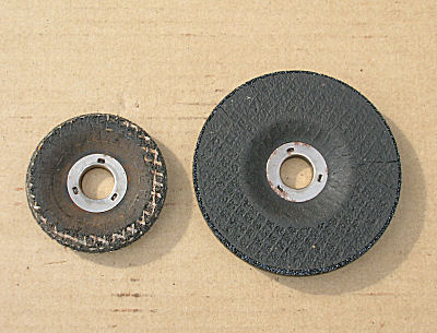
The replacement wheel even looks large by comparison. When the consumables are consumed, replace them. Trying to get the last little bit of use from a wire brush, grinding wheel, or other device is not worth the effort. The old saying that a new broom sweeps clean holds true, and new consumables work better than the old ones that are worn out. -
IForgeIron Blueprints
Copyright 2002 - 2011 IFORGEIRON, All rights reserved
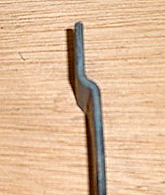
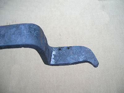
BP0377 Wiggle Pick
by Bill Epps
A wiggle pick is a tool used by arrow head hunters.

The guy I made it for is a arrow head hunter and uses it for digging in the ground. I am not real sure exactly how it is used, the fellow just wanted me to make one for him. So I cut it out with a torch, then forged it to shape.

To the best I can find out you push down on the top and work the handle to force the point into the earth then pry up the dirt and hope you find something -
IForgeIron Blueprints
Copyright 2002 - 2011 IFORGEIRON, All rights reserved
BP0374 Gear Puller
by Glenn Conner

The local mechanic needed to replace this gear on a timing shaft. In getting the old gear off he tore up the flange with his 3 prong puller and pry bar.

The old gear had some damage and was close to $100 to replace. He located a junk motor for less than half that but the gear was stuck on the shaft. And he had already destroyed one gear trying to remove it.

The damage was the cause for replacing the gear, no by the mechanic. The replacement gear had to come off to be used. So he called a blacksmith.

First you find a piece of steel from your resource pile. The welding rod is just to indicate size. I figured 1/4 inch plate would hold up to the task.

Check to see that it will work and mark the center.

Using your handy hole punch, punch a hole where the shaft would be located. While your at it, cut away any excess material.

Mark the location for the 5 bolt holes.
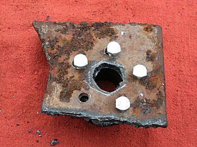
Drill 5 slightly oversized holes.

Mark the location for the BIG nut to properly fit over the end of the shaft on the engine.

Assemble the whole thing. The bolts are screwed into the gear to assure proper alignment.

This is where you use the "other" half of the plate to help align the "C" clamp.

Put the BIG bolt into the BIG nut and see if everything fits as it should.
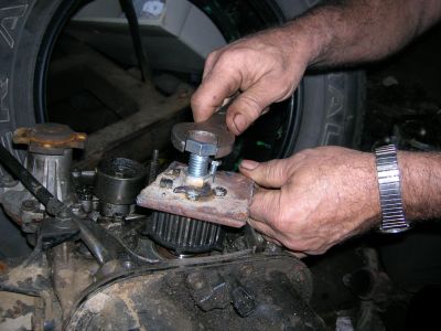
The mechanic put the gear puller on the gear, tightened down the 10mm bolts, put a 15/16" wrench on the BIG bolt and with a flick of the wrist removed the gear.
The idea was to use all 5 small bolts to secure the great to the plate. The Big bolt was then used to press against the end of the shaft and pull the plate, 5 small bolts, and the gear upward all being properly aligned to the center line of the shaft.
I am a blacksmith, I can make the tools to do the job. It just takes a little thought on how to keep things straight and to use a simple inclined plain (screw) to do the work. You can exert a tremendous amount of pressure with a set up like this so even though it is simple, use caution and wear safety glasses.
-
IForgeIron Blueprints Copyright 2002 - 2011 IFORGEIRON,
All rights reserved
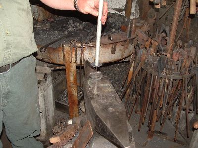
BP0373 Spiral Candlestick by McRaigl, Photos by Mike-hr
Design credit goes to Peter Parkinson from his book “The Artist Blacksmith”.

I like to use ¼ by ¾ for this, starting with a piece somewhere between 18 and 24 inches long. You only actually “need” about 6” of material, but it’s nice to have a handle and not have to use tongs so much.

I like my candle stick to be about 6” tall, and I like the upright to be about ¼ x ¼ at the base with a long taper to a point at the top. Given we’re starting with ¼ x ¾, I put the shoulder in at about 2 inch figuring it will triple in length when we draw it to ¼ x ¼.

The radius on the offside of the anvil seems to be the most efficient way for me to pull off this long of a taper. I really liked the radius on Mike-hr’s Peddinghaus. It’s a bit smaller radius and more consistent than my Peter Wright. A guillotine tool or a smithn’ magician would also work well here.

Should look something like this when you’re done.

From the base of the taper ( ¼ x ¼ ), taper the width back 2 inches to the full ¾ width preserving the ¼ thickness. Try to keep everything straight as you go.

Now fuller the next two inches such that you maintain the taper you started in the previous step. In the past I have “flatted” out the fuller marks. This time I decided to keep them and add some fuller marks to the taper we made in the previous step also just for texture. I think I’ll do them this way from now on ‘cause I like the way it turned out.

Should look something like this. Notice how the original square section taper ended up at just about 6” like we predicted, then we tapered the next two inches maintaining the ¼ thickness, then gave up the ¼ thickness by fullering to get additional width in the next two inches. You can also see the texture left by the fuller.
Now make a 90 degree bend at the base of the square taper. Since I decided to leave the fullering marks for texture they need to be down (on the inside of the 90 bend).

Like this.

Now put it in the post vise with the point down. Use an oxy/acetylene torch to localize the heat and begin spiraling the piece keeping the material somewhat flat. I find it easier later on to get the thing to stand up without being wobbly if I keep the top surface pretty much level with each successive wrap.

As the width of the material increases once you get it wrapped a little it requires more effort and puts a lot of strain on the smaller section that you wrapped first so it’s a good idea to keep a squirt bottle handy to cool the first few wraps before getting too far.

Focus the torch on the tangent of the arc. Also, heat a larger part of the outside than the inside to avoid tearing.
Continue wrapping ‘til you get to the end of the fullered tapered section.

I normally use a hotcut chisel with a lot of rocker to cut the piece off on a curve. Mike-hr had a curved chisel with a radius I really liked so I used it.

Here’s what the cut is looking like.

File off the nasty sharp edge left by the hotcut.

Get the base hot and put the point down in your hardy hole. Use a ball peen and lightly tap the center of the spiral. The aim is to make the piece “sit” on the perimeter of the spiral so it’s not wobbly. Sometimes you have to doink around the edges a little ‘til it sits good.

Hot file the base if necessary to help it sit flat and stable. It's usually necessary to reheat the long taper afterwards and adjust it so it stands up nice and straight. The torch will come in handy so you can localize the heat right at the base so as not to mess anything else up in the process.

Brass brushing the base shows off the texture left by fullering real nice.
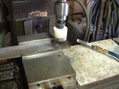
I normally use brass for the drip pan by tracing around the bottom of a small WD-40 can and cutting it out with scissor snips. But we didn’t have any copper handy at Mike-hr’s shop. However, a 2-1/8 inch hole saw and a Lagun mill made short work of cutting out a perfect circle.

We drilled a small hole while everything was in the mill vise before we cut out the circle. The 2-1/8" hole saw left us with a perfect 2 inch circle.

I don’t own a swage block and normally use a juniper stump. Mike-hr’s swage block sure worked nice. I left the center near the hole flat and just put a touch of curve around the rim. Watch those fingers, OUCH!
A piece of small pipe or a small monkey tool work well to seat the drip pan on the upright.
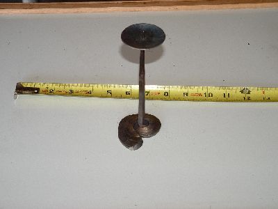
Now just clean it up and apply bee’s wax and is should look something like this. The spiral base reminds me of sea shells, and a lot of my family really like the beach so this has been a big hit with the kinfolk. -
IForgeIron Blueprints Copyright 2002 - 2011 IFORGEIRON,
All rights reserved
BP0370 Tool Holders by Glenn Conner
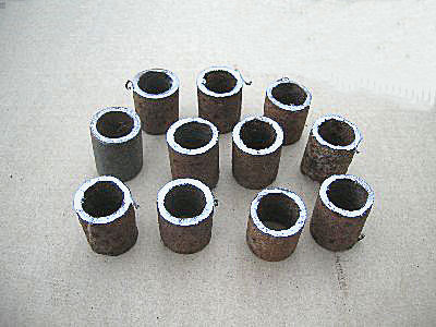
Start with some scrap 1/2 inch pipe and cut it into 1 inch long sections

The bar is bent down for 2 inch and then back for 1-1/2 inch not counting bend. Repeat for the other end.
The end was rounded and then curved to give it some character other than a quick cut with a saw. It looks like a blacksmith did the work. It doesn't take but a few hammer blows and set your work apart from anything anyone else would make.
A 1/4 inch diameter hole is either drilled or punched into the "foot" so a screw or nail can be used to attach this to a wall etc.

Weld a piece of the pipe into the corner. Yes, that white stuff got my attention also. ZINC !! This pipe was old galvanized. The rest was scrapped and new sections were cut from another pipe that was not galvanized.

The next piece of pipe is welded on to the holder at 2" on centers.

You can now hand your screwdrivers up and instantly see not only the handle you want but also the end you want to use. It sure cleans up the tool drawer.

You no longer have to worry about getting the right tool, you just reach for it.
A second holder was made for a friend that is a mechanic. Two days later he called and ask if I could make him another holder but this time use 1/2 inch and 3/4 pipe. Sure, no problem, I can do that. After all I am a blacksmith.
That mechanic is a smart fellow. He is using the 2nd holder to hang the long extensions from his socket sets, 3/8 drive extensions fit into the 1/2 inch pipe and 1/2 inch drive extensions fit into the 3/4 inch pipe.
-
IForgeIron Blueprints Copyright 2002 - 2011 IFORGEIRON,
All rights reserved
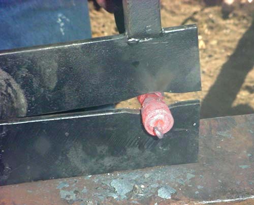
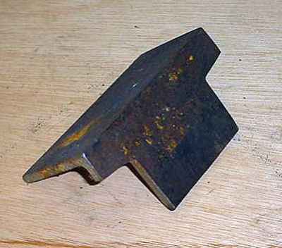
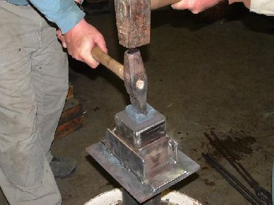
BP0369 Heading Blocks and Bottom Tools by Mike-Hr and McRaigL

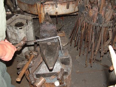
We’re going to make this heading block tonight. It is basically a very small swage block, or a remote hardy hole. Once we discuss the construction of the heading block, we’ll use it to make a hardy tool. The question came up, ‘Why is this block necessary? Can’t I just use the hardy hole in my anvil to make this tool?’ Having this block as a stand alone item makes team striking quite easy, and a lot of fun. The striker or team can rotate around the piece, which helps the tool upset more uniformly. We’re going to demo bottom tool making at an upcoming hammer-in, and I’m a lot less worried about someone mis-striking and hitting this block than my nice anvil. Another point is that London pattern wrought anvils may be weak around the hardy hole. I’ve seen a few anvils broken at the hardy hole. Using this block just seems safer.

This is a 4 inch long piece of .250 wall, 4 inch sq. tubing. In the middle is a piece of .180 wall, 1-1/2 in sq. tube. It has an inside dimension of approx. 1.140 inch, so it will act as a relief hole for the one inch square hardy hole we’ll weld to the top. I filled the void with various pieces of 1x2, 1x1, 1x1/2, to create a solid mass.
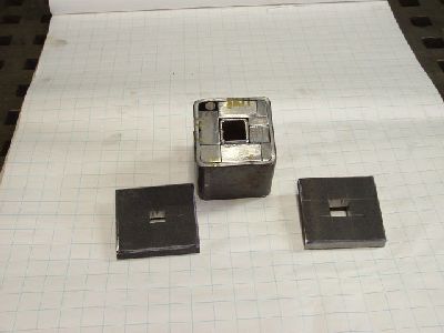
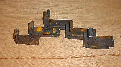
Here’s the block, with the two cover plates, both ¾ x 4 x4. One plate has a ¾ square hole, the other has a one inch square hole. There are several ways to make square holes, I made these by drilling a hole in the middle, chasing the corners with a 1/4inch endmill cutter in the milling machine, and handfiling the final radius away. I Mig welded the puzzle pieces together, and welded the plates on the ends.

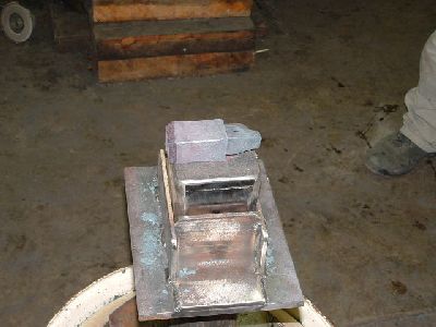
The heading block is finished. We’ll make a socketed holder, so we can flip the block over, giving us either a ¾, or 1inch swage hole. (two blocks in one)

I made the socket so each axis has a 1/8 inch gap. The block won’t get stuck if it deforms.
We made the stand from a scrap truck rim, a cover plate, and a length of 4-1/2 inch O.D. pipe that carries through to the floor. The top of the heading block is the same height as my anvil, so I don’t have to re-program my body to hit things on it.
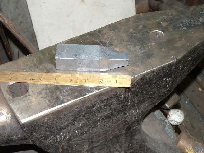
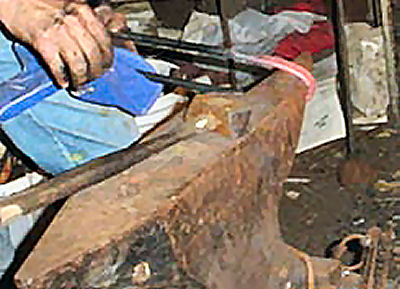
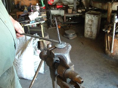
Part II. Let’s use this thing to make a hardy tool. To make a one inch shank hardy tool, we start with 4 inches of 1-1/4 square, and forge a taper, leaving about 5/8 inch square on the end.
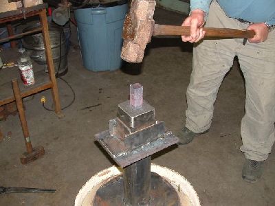
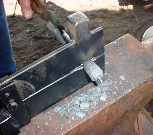
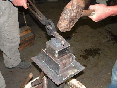
We took a near welding heat, quenched the top inch, and started whacking on it. We did some two man double striking , and switched from North-South orientation to East-West every 10 hits or so to help the piece sink down evenly.
It looked like this after the second heat. The shank is starting to take shape, and it’s getting thicker. We chamfered the end each heat to minimize mushrooming.

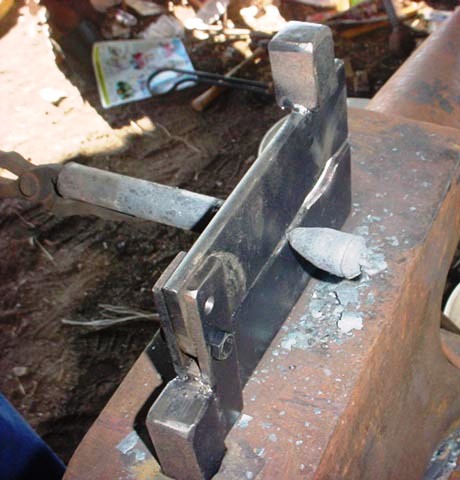
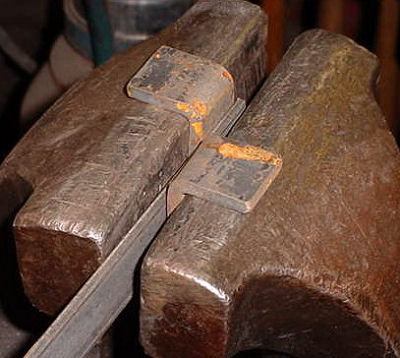
After the 5th heat, it’s ready to turn onto a tool. We squared it up a bit, and chamfered the end. We’ll turn this into a 1 inch round swage.
We started with a round nose set hammer to establish the channel. It gives the 1 inch round a place to sit when we form the swage.
After we were happy with the depth of the swage, we tilted the round bar to ramp down the edges of the block.

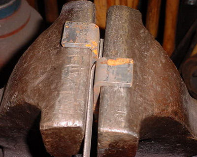
Here’s the finished piece after case hardening. The piece rotated on its hardy axis a few degrees toward the end. We didn’t switch North-South orientation while forming the round depression, and I think the 15 pound hammer made more headway than the 8 pounder. Maybe someday we’ll heat it up and square it with a big wrench.
Thanks to Mark Asprey for the heading block idea and coaching. -
IForgeIron Blueprints
Copyright 2002 - 2011 IFORGEIRON, All rights reserved
BP0368 Bender (construction information)
by Pmusics
This construction information should you give more an idea to build your own bender, than give you some exact measurements. The drawings are slightly different to the photographs, since it was already re-designed and I just left out unnecessary cuts in order to save time (and money). Way of working:
Find a useful double-T profile and cut about 400mm away from it
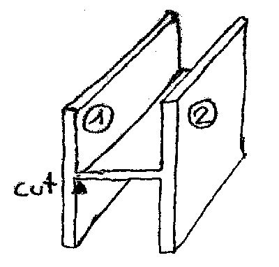
Separate the 2 sides if you like a smaller bender than the original T-profile has.
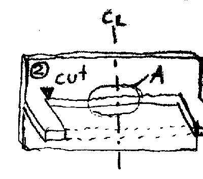
Cut out a center part wide enough to get access into the bender. This will not affect the material entered into the bender, if the center of the support-wheels is higher than the center line (horizontal) of the T-profile (!!)

I did choose about 65mm wide (so the support wheels are not stressed too much (as longer they are as less stable).
Modified drawing (not as in photograph) to cut out the side piece easier.
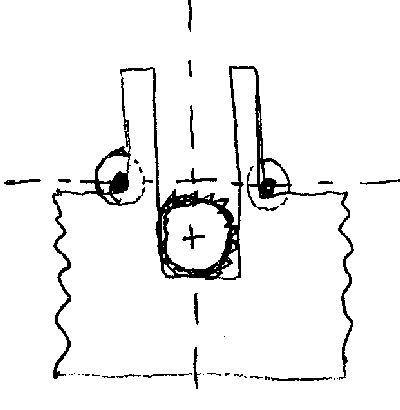
All about the dimensions. First, make sure that the center of the support wheels is higher than the horizontal center line of the T-profile. This will allow the material to go through the bender without interfering with the horizontal plate of the t-profile.
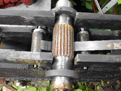
The support wheels I used are 30mm in diameter, the cartan wheel is 44.5mm in diameter (measured over the teeth). Since the cartan piece was ground at the shaft to its “solid diameter” please keep in mind to cut the vertical piece according to its shaft diameter (and not the diameter measured on the teeth!)
You should allow the cartan wheel to go complete underneath the horizontal center line of the support rollers (even if never used, it will give you “enough play for adjusting the position of cartan wheel in regard of the desired bend-radius

Position of two little fixations of support rollers (horizontal) and position of steel-tube (vertical). Allow a little play for the support roller’s axe and allow a little play in the tube for the thread bolt to move up and down

Basic drawing of support wheel diameter 30mm and its hardened steel bolts.
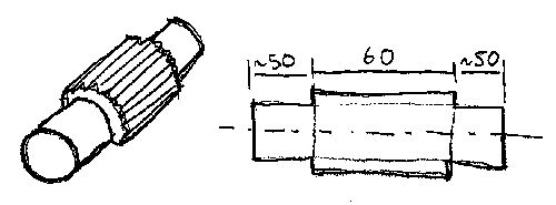
Basic drawing of cartan wheel. I ground away the teeth over about 50mm on both side. Than took a sandpaper and ground the shaft “round”. If you have a drill bank at home you can use this one to take away the teeth of the wheel.

Side view of bender. The tubes are not used anymore (left/right side) and the “windows” are not used, cut them out as shown on drawing. Bottom plate soldered to give stability to bender.

Feel free to determine the “wideness” of your bender yourself, but keep in mind that as wider the bender will be, as longer the support rollers are and as less stable they got.
Here again, I used a 44.5 mm diameter cartan, did grind away the teeth to both ends of the shaft and cut then out the vertical area to allow the shaft a little play but still make sure the inner diameter (of teeth) is bigger than the area cut out. This will hold the cartan wheel in the center position. I used some washers to center the support wheels.
Here you see the horizontal movement of cartan done by thread bolt. This must probably later be redesigned because after bending the circle the bolt must be completely loose in order to lift out the cartan and evacuate the bended circle. Please take care that the bolts will go below the bottom line of the bender. -
IForgeIron Blueprints Copyright 2002 - 2011 IFORGEIRON,
All rights reserved BP0366 Multi-position vise holder by Rich Hale
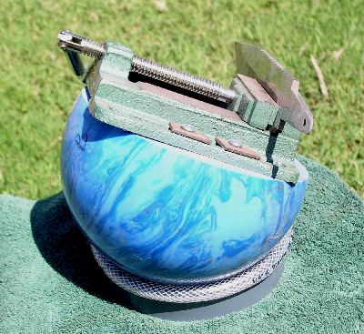
I got a bowling ball at a thrift store for $1.29. Sliced off a slab with a band saw. You can do this with a hand saw, it cuts pretty easy. Flatten the cut area with a sander or rasp if needed. The vise is a cheap one that was about $13 new.

Four metal screws about 1 3/4 long secured it to the ball. The ring was cold turned from 1/8 x 1 1/2 steel and the ends welded. A piece of 1/4 inch. ID. hose was split and fitted onto the edge of the ball. You can turn this ball in almost any position and it will stay put for light work like filing or sanding. I did not measure the ring make it fit the ball so the ball does not extend below the bottom line of the ring with the hose in place.
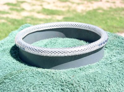
Detail of the ring.
BP0309 Car Radiator Clamp Holder
in BP 300 Series
Posted
IForgeIron Blueprints
Copyright 2002 - 2011 IFORGEIRON, All rights reserved
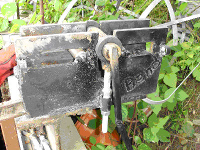
BP0309 Car Radiator Clamp Holder
by Jim Carothers
Saturday afternoon I put all new hoses on my wife's Chevy. I had a real hard time getting the factory GM spring band type clamps off and back on. I like the way these clamps work -- nice even tension on the hose / joint. I don't like working with them. There are special tools for these clamps; but they are expensive, and not available on Saturday afternoon in Perry, OK. I only have to do this about every 100, 000 miles.
Getting the clamps back on was the hardest part. I finally got down to one last clamp -- the big one on the bottom of the lower radiator hose. There was just no room to get any of the 7 different pliers I have in there to squeeze the clamp to open it. If I could get a squeeze on the ears, it was not enough to fully open this large (2") clamp and get it up onto the hose.
After about an hour working on this one last clamp, I changed projects (took a break and went to see my farrier neighbor). The idea of squeezing the clamp out of the vehicle and holding it open with a piece of wire occurred to me upon returning to the Chevy. I am likely not the only person to think of this; but working alone, it was almost a revelation to me. I had the hose on and the clamp positioned easily in a few minutes. Cutting the wire finished up the job.
The clamp in the photo is a small clamp used on the heater hoses, but serves OK as an illustration.