

Steve Sells
-
Posts
9,162 -
Joined
-
Last visited
Content Type
Profiles
Forums
Articles
Gallery
Downloads
Events
Posts posted by Steve Sells
-
-
IForgeIron Blueprints
Copyright 2002 - 2011 IFORGEIRON, All rights reserved
BP0332 Bail Handle
by Glenn Conner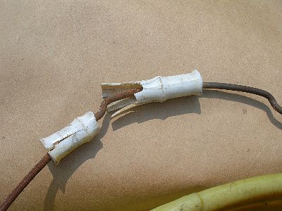
You ever have this happen? The bucket is still useful but the handle cracked and slips out of place and the wire digs into your hand.
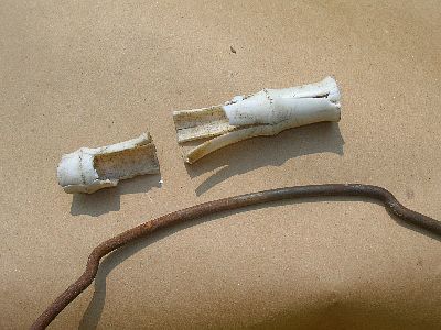
Cut the old handle off the bail.
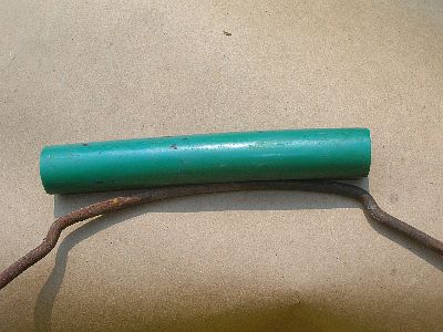
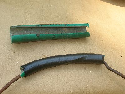
Cut a section from that OLD garden hose you just can not stand to throw away.
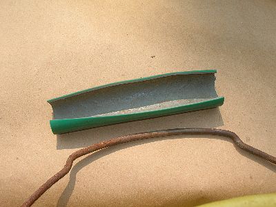
Split the garden hose.
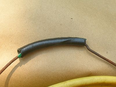
Put in over the bail and tape it into place using electrical tape.
The hose was the cheap 1/2" style and it wrapped inside itself. This would be uncomfortable for the hands.
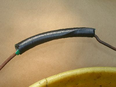
So do it again.
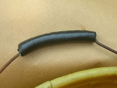
Now you have a handle with the split at the top and a smooth section against your fingers.
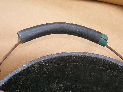
This handle is several years old is on a bucket I use for coal. It keeps moving to the side of the house where the wife has her flowers for some reason. So, I had to put the handle on the yellow bucket.
-
IForgeIron Blueprints
Copyright 2002 - 2011 IFORGEIRON, All rights reserved
BP0335 Adjustable Anvil Stand
by Glenn Conner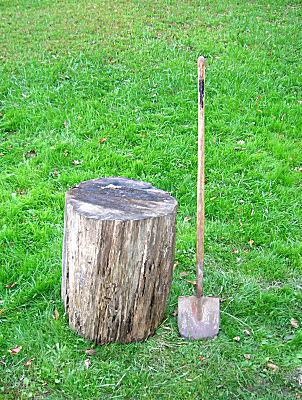
Find a tree and bury it into the ground. Leave the proper amount of the log above the surface so that when you put the anvil on the stump the anvil face is at the proper height for your comfort.
Adjustments can be made. Lowering the stump is just a matter of triming the height a bit. Raising the stump . . . . . well that takes a bit longer, and filling in the hole.
This is actually what a lot of the old smiths did, the one in my uncles old shop was cut off 6 foot down as they got tired of digging to remove it.
Jr Strasil
-
IForgeIron Blueprints
Copyright 2002 - 2011 IFORGEIRON, All rights reserved
BP0334 Adjustable Anvil Stand
by Glenn Conner
For those that are using Rail Road track for anvils, just get a 20 foot section of track and bury it 17 feet +/- into the ground, leaving the proper amount sticking out of the ground for use as an anvil.
This puts all the mass of the track directly under the work.
-
IForgeIron Blueprints
Copyright 2002 - 2011 IFORGEIRON, All rights reserved
BP0336 Adjustable Anvil Stand
by Glenn Conner
Measure the diagonal of the bottom of the anvil and find a drum with a diameter that is a bit larger. This was a standard grease drum, about 30 gallons or some 120 liters.
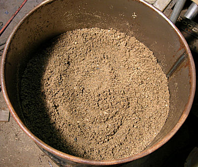
Fill the drum with sand. This one took 4 each 5 gallon buckets of sand.
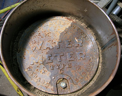
As I did not want the anvil to "sink" with use, I put a water meter cover (from the junk yard) on top of the sand. It will take a lot to drive that down into the sand.

I then added a bit of wood to insulate the anvil from the water cover.

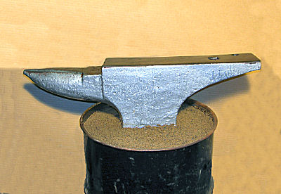
Add one anvil and measure distance of the face of the anvil from the floor.
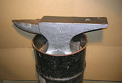
Add or subtract sand to reach the desired height. For me this was 32" from the floor to the face fo the anvil, knuckle high plus 1-1/2 to 2 inches.
This stand is inexpensive, quick to build, and has a good bit of mass directly under the anvil. It is difficult to tip over and infinately adjustable with the anvil face from 29 inches to 36 inches for a range of 7 inches. The one design element I like is the factory rolled edge on the top of the drum. As the top of the drum is above the bottom of the anvil, be careful as this could be a pinch point, or you could hit your hand on the rim. If you want to lower the anvil even more, the top can be cut to the desired height. If this is done, the sharp edge must be rolled or protected in some manner so no one gets injured.
except for about an inch at the top will make the anvil more stable (resist turning), deaden the anvil and leave an inch high edge around the anvil to keep tools from falling off and some tools, hardies, center punch etc can be stuck into the sand for easy access. A short pipe of the right size embeded in the sand would work as a holder also.
When you get the working height the way you want it, filling the container the rest of the way with sand
-
IForgeIron Blueprints
Copyright 2002 - 2011 IFORGEIRON, All rights reserved
BP0337 Ash Dump
by Glenn ConnerSometimes the tuyeres fill up with ash and the forge blower can no longer push enough air to the forge through all the clinker and ash. I dumped the ash, cleaned the fire, and the forge still won't work right. The problem is something getting hung in the pipe and the pipe filling up with ash.

I solved the problem by cutting the flapper off the bottom of the pipe, and running the pipe into a bucket of water. Ash now falls to the bottom of the pipe, into the water, and the hot coals are extinguished.
The pipe only needs covered with just enough water that it does not bubble. Check on the bucket from time to time as it fills with ash and needs emptied.
-
IForgeIron Blueprints
Copyright 2002 - 2011 IFORGEIRON, All rights reserved
BP0339 Bandanna /Neckerchief Slide
by Jim Carothers
Bandannas are cool. They look good with the smith’s or cowboy’s outfit and they really do help to keep you cool as well.
I usually try to set my demo forge up so that the wind is on my back – keeps the smoke and some of the heat out of my face. On a hot Oklahoma day, that damp bandanna around one’s neck and a breeze on the back are right refreshing. The bandanna also helps to keep the cinders and stray fire from going down the back of your shirt.
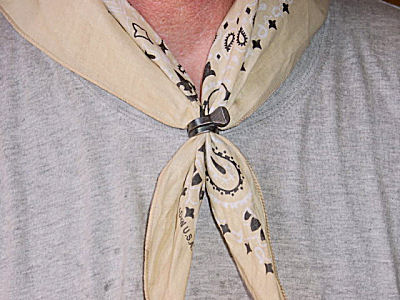

So as not to have to struggle with tying a knot in the bandanna to keep it in place, I make a simple slide out of a large horseshoe nail. A nice bandanna with a hand forged slide is a pretty good item to sell at demonstrations. I got a nice assortment of bandannas from the local Hobby Lobby store. You can steel letter stamp the customer’s initials on the head of the nail (slide) for a personal touch.

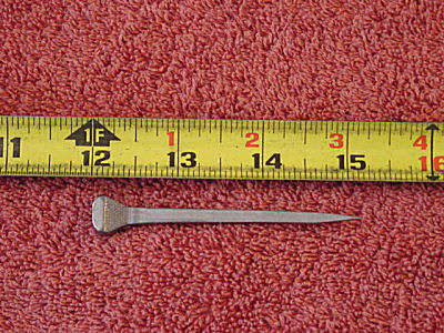
Start with a large horseshoe nail. These are about 3-1/4” long.
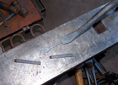
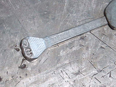
If you are going to steel letter stamp something on the slide; it’s best to do it with the horseshoe nail still flat. The “hold down” was made from an old automotive lug wrench.
Begin the bending of the slide by working on the tip of the nail. The tip can be rolled cold or hot. Put a little curl in the end to cover the sharp end.

Take a good orange heat; cool the tip of the nail. For a simple mandrel, I used a piece of ½” round bar with a scrap of flat strap welded to the side. A quick slotting of the side strap with a hacksaw provides the hook to hold the tip and start the bend.

Bend the rest of the nail around the mandrel. I used tongs and smooth jaw pliers to do this bending.
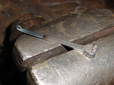
Reheat the now formed slide, wire bush, and hot wax or oil to help prevent rusting. Brushing with a brass brush is also a nice touch.
Jim C.
President (2006) Saltfork Craftsmen ABA -
IForgeIron Blueprints
Copyright 2002 - 2011 IFORGEIRON, All rights reserved
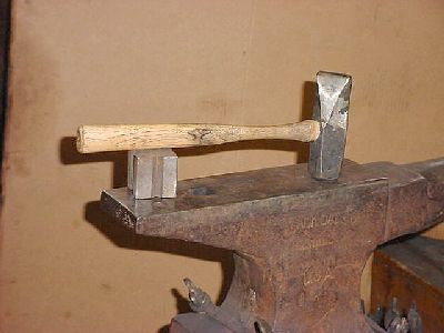
BP0340 Better Hammers - Cheap
by Jerry SauveBeing a mechanic I always have several beat to death ball pein hammers in my tool box. The problem with a ball pein is that when you hammer with it the balance is never just right. The hammer side weighs more than the pein side. This is how I went about correcting it.
The whole problem with blacksmithing is you don’t have deep enough pockets to buy the tools you want and as a weekend warrior don’t have time enough to make what you want for tools. It is to this end I came up with a relatively cheap solution to that Holy of Holies a hammer that feels good in your hand and helps you do good work. With a little practice I might even be able to forge lightning bolts with it.
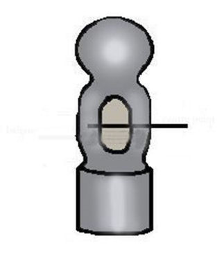
Find the center line of the hammer
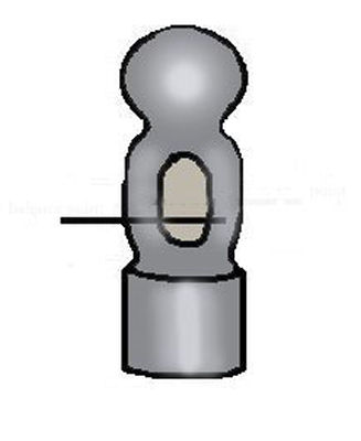
Find the balance point of the hammer
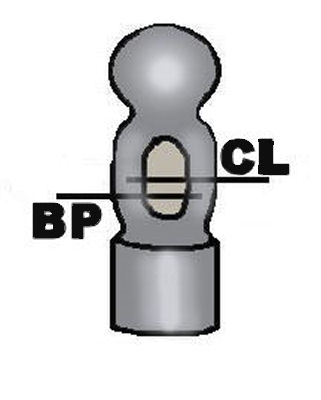
Measure the distance between the two points.

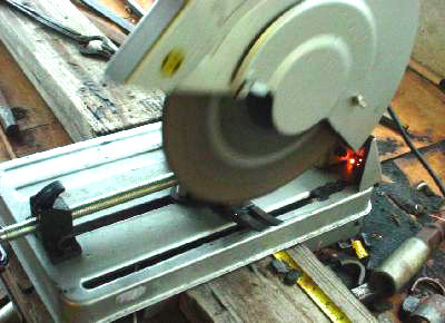
Cut off a little bit less than the measured distance off the striking face of the hammer.
Take a grinder and bevel the striking face of the hammer.
If you have been fairly careful in your work the balance point and the centerline should be very
close to one and another. This will give you a hammer that is a joy to work with while blacksmithing.
Notes
I started with a 32 ounce hammer and end up with something less than that. How much to cut off depends on how much bevel you are going to put on more bevel=less steel cut off. How much bevel to put on the hammer I will leave up to you but I was fairly aggressive with the bevel and started just about in the center of the striking face grinding and worked my way out.
I am waiting until I break the hammer handle before I retemper the face. For now it seems to be holding up OK so long as I don’t hit cold steel with it.
You don’t need to get a laser measuring tool to do this I did it all on a piece of 1/8 flat iron for a balance point and a sharp pencil for a measuring tool.
Cut the face as parallel as possible to the existing face it means less grinding later. -
IForgeIron Blueprints
Copyright 2002 - 2011 IFORGEIRON, All rights reserved
BP0341 Hammer Adz
by Bill Epps
Start with a cheap H/F claw hammer.

Drive the handle out of the head.
Cut the claws off with a chop saw.
Head with claws cut off.

Take a good heat and start flatting and drawing the hammer face.
The hammer face drawn out and cleaned up with a grinder. Form the shape of the blade.
Shape the radiaus of the blade. You want it to make a cup shape cut in the wood.
Harding the cutting edge
Testing the hardness with a file and using the carryover heat to draw the cutting edge.

After sharping, the handle is put back in the head of the adz.
The adz is ready for use.
-
IForgeIron Blueprints
Copyright 2002 - 2011 IFORGEIRON, All rights reserved
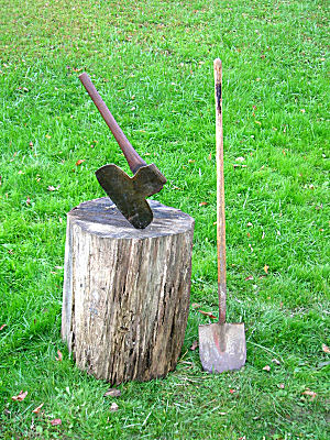
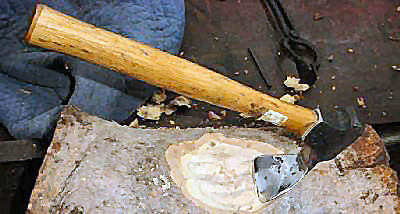
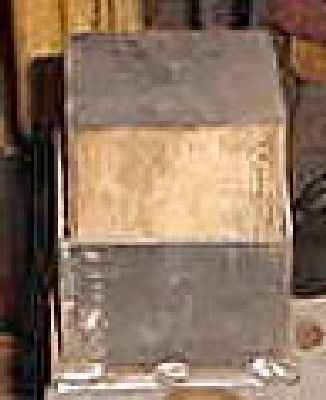
BP0342 Handles
by Jerry Carroll
I started with a thoroughly dry hickory sapling 4" in diameter at the biggest end. I cut off the 14" I needed for the handle.

I split the 14" piece in half and squared it up on the table saw.
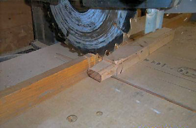
I centered and marked the size needed to fit the eye of the tool the handle will be used on. Raising the radial arm saw blade I took off wood down to the line marked and back the length needed to go thru the tool eye.

I used a draw knife--rasp and heavy cut file to shape the handle to fit the cutting tool on the right.
Here's the finished handle in the tool--sanded, linseed oiled and flamed with a propane torch then steel wooled smooth.
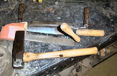
Here's another look at the finished tool with the tools used to do the handle. I took my time (I'm retired you know) and finished in little more than an hour. I didn't have any store bought handles that even come close to fitting.
-
IForgeIron Blueprints
Copyright 2002 - 2011 IFORGEIRON, All rights reserved
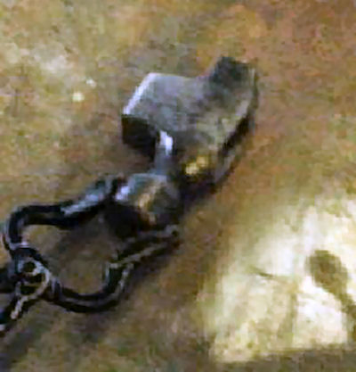
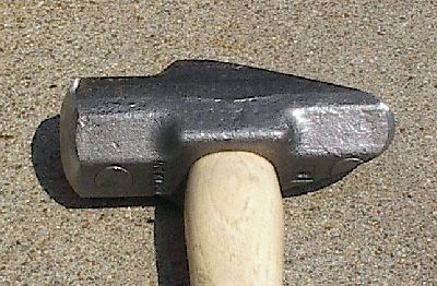
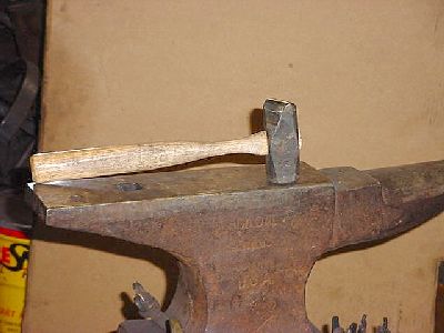
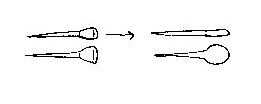
BP0343 45 Degree Pein Hammer
by B. Norris

Here is a picture of a 45 Degree Pein Hammer made by reforging the ball end of a 32 ounce Ball Pein Hammer. Prior to being reforged it looked just like the one it is resting on. I bought the heads for $1.00 each at an antique shop. I bought every single one they could find! I am right handed by the way, might help figuring out which way to twist the pein, or it might just serve to confuse. You can reforge one of these Ball Pein Hammers into just about any kind of pein that you want: straight, cross, 45 degree, or anything in between.
I LOVE my 45 Degree Pein Hammer for drawing out. No more standing at the anvil with the ends of the tongs and hammer right next to the family jewels! Seriously, they are much more ergonomic to work with. I like it so much that I have bought one of the "double-faced sledges" to grind 45 Degree Peins on both ends with differing radiuses, looking for a larger radius than I got from the Ball Pein Hammer, and a bit more weight. I might be able to get to grinding it tomorrow and put up some before and after pictures.
The Picard brand hammers are imported from France. I used one at a blacksmithing class once and liked it a lot (the smith who loaned it to me had dressed the face perfectly!) MOB handles are a bit "beefier" and are less of an oval shape, more like a rectangle with the edges rounded over. The same kind of shape to the eye that Tom Clark uses on his hammers. Easy to see the difference, but hard to explain!
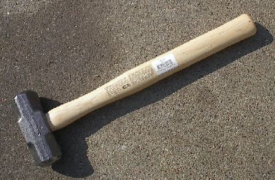
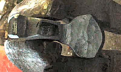
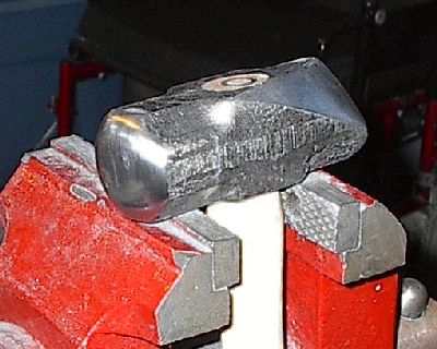
Here's the before picture. This cost me $5 and some change at the local Menard's.
Here's the plan. The hammer is marked "3" on the head, for 3 lbs., and weighs 3 lbs., 6 ozs. with the handle.
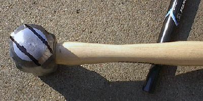
After the angle grinders attack the poor hammer began experiencing confusion as to its identity! "Am I a sledge or a pein?" The hammer thought to itself. "And, if I am a pein, am I right, or left?" I apologize for the cheesy dialog, but it is a Quarter Pein hammer intended for use by a right-handed individual.

Hot off the grinder. I used a fresh 24 grit belt, still took awhile.
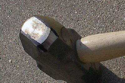
Here it is at 120 grit. The hammer now weighs 3 lbs., 1.6 ozs.. From here on out it is hand sanding, all the way down to 600 grit. First though I'll go get some metal hot, hit it, and take pictures of the impressions.

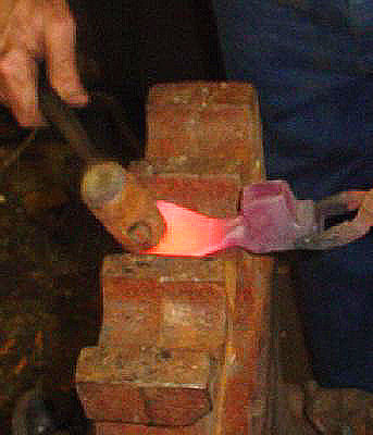
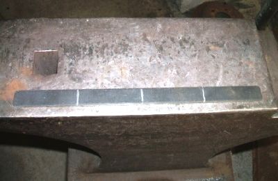
The notch in the edge of the spring is made by the pein end. The dent on the flat of the spring, it is about the size of a quarter, was made by the other end of the hammer.
Here it is sanded down to 600 grit. I like to sand my hammers down by hand. The belt grinder leaves the faces that need to be round, and smooth, looking like they are faceted. Sanding by hand smooths it all out and gets it to how it needs to be.
Have any flea markets in your area? If so, find the guys that sell the cheap tools, and tell them what you are looking for. The more you buy, the more likely they are to work with you. Lots of things to be done with ball pein hammers: spike tomahawks, specialty forging hammers, handled punches, woodworking adzes, hot cuts, etc. I could think of more, that was just off the top of my head!
I would prefer to reforge this one to make the pein, but doing so would burn up the handle, adding an additional $6 to $8 for a new handle, and putting the total cost up around $12 to $14. I probably have less time into regrinding this one than I would if I reforged it, put a new handle on, and then ground and sanded it. I just don't seem to notice the passage of time when I'm working at the anvil though!
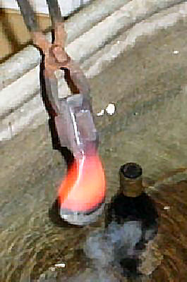
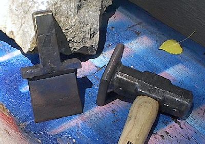
Here is another way to use these cheap hammers. I had to pay someone who had the equipment and expertise to work with tool steel (I used stock from a leaf spring.) I had the hot cut welded at the same time and the whole job cost me $25. Still, it was cheaper than if I had bought a flatter off the internet, never mind the hot cut hardy. -
IForgeIron Blueprints
Copyright 2002 - 2011 IFORGEIRON, All rights reserved
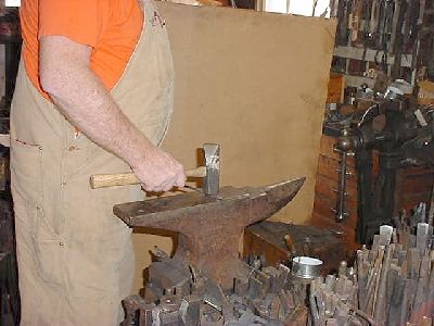
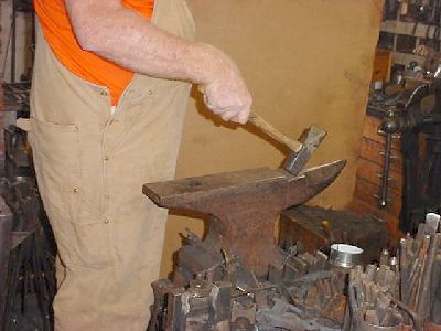
BP0344 Hammer Technique
by Jr. Strasil aka Irnsrgn
We are all different and we all use different techniques to do the same job. The results may be the same and they may not. What works for some will not work or be COMFORTABLE for others.
Hammering hot iron on an anvil with a hammer of our choosing is the basis of blacksmithing and the reason for the blacksmith trade in the first place.
The technique I am going to explain is basically the way my Grandfather taught his sons and the way my father and uncle taught me at a very early age during my apprenticeship. Like everyone else I modified some of the techniques to make things easier for me and to improve the way I do things.
I don't think that everyone should do things exactly as I do or feel that they are wrong if they don't do it my way. I just know that this way works efficiently for me, and after 55 years of using these techniques, I have no problems with my hand, wrist, forearm, elbow or shoulder.
Procedures covered will include, hammer control, hammer choice, how to hold a hammer, Preparing your body for using a hammer, posture, exercises to improve your ability to wield a hammer, anvil height and vision problems.
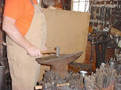
When I see a Smith all HUNCHED over his Anvil trying to hammer hot iron, I know its one of two problems, either his Anvil is TOO LOW or his vision is IMPAIRED.

IMPAIRED VISION - This can mean that the Smith NEEDS Corrective Glasses or that the smith is using READING glasses to work with, and the focal length of the bifocals is to short to make things clear. I have my bifocals so that I can see CLEARLY at arms length, and the top of my bifocal is at the center of my cornea. It makes my neck hurt to have to tilt my head back to see clearly.
ANVIL HEIGHT -- This is a touchy subject and the root of much controversy. You will hear that the tips of the fingers should touch the anvil face, the second knuckle should touch the anvil face, a closed fist should touch the anvil face and the anvil face should be at the joint of the wrist. All these references are, is a measurement of preference for each Smith, after they find the RIGHT WORKING HEIGHT of their ANVIL. Remember each person is different, some have longer arms, some have shorter arms. Two people of approximately the same height may have as much as 1 or more inches difference in the COMFORTABLE WORKING HEIGHT of their Anvil.

There is only ONE factor that should determine the PROPER ANVIL HEIGHT for each person, that being when the individual is STANDING in a COMFORTABLE POSITION at their ANVIL, with the ELBOW SLIGHTLY BENT, and the hammer in a COMFORTABLE GRASP. The HAMMER FACE should be resting SQUARELY on the Anvil Face at the End of the Stroke.
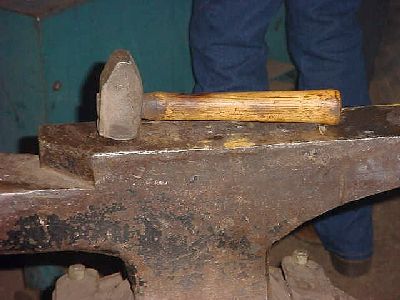
HAMMER CHOICE - Head design, handle style and length and head weight are all another touchy area, and causes much controversy among smiths. Basically a Hammer should feel like A NATURAL EXTENSION of your Hand. A typical DOUBLE FACED Engineers hammer is a good example of a BALANCED hammer head, both faces are of more or less the same weight and it has a good feel while in your grasp.
This is an example of a very UNBALANCED HAMMER HEAD made by a commercial hammer co. and is UNWIELDLY IN APPEARANCE and FEEL. It takes more effort to control and thus more heats to accomplish a specific procedure as you will have a tendency to slow down, fighting the unwieldy head and thus accomplish less.

HAMMER HANDLE- This is another topic that illicites much controversy among smiths. A HAMMER HANDLE should feel COMFORTABLE while grasped in your hand. Blacksmith handles usually come in lengths of 18 inch, 16 inch and 14 inch lengths and usually have a larger handle area and a larger eye end than machinists hammer handles. They are usually an OVAL shape and each blacksmith will ALTER the handle to their liking. The NECK of the handle ( the area between the head and the part you grasp) is usually smaller than the grasping section. I have found that working down (slimming down) this area gives a little more FLEX to the handle, and thus does not TRANSFER as much of the SHOCK AND VIBRATION of the IMPACT to your hand, wrist, arm and shoulder. The SHOCK and VIBRATION can cause INJURY to your arm and also impart FATIQUE to your appendage.
HOW TO HOLD A HAMMER -- You should HOLD the Hammer at the END of the HANDLE, with about an INCH or so of handle sticking past the HEEL of your hand with your HAND GRASPING the HANDLE and your FINGERS wrapped COMFORTABLY around the handle. Now BEND YOUR ELBOW enough that the HAMMER is STICKING STRAIGHT UP ---- RELAX your GRIP enough that the Hammer STARTS TO SLIDE thru your HAND ----TIGHTEN your GRIP enough that the hammer QUITS SLIDING thru your hand, this is the THE GRIP you SHOULD use on your hammer. You DON'T need to SQUEEZE it to death. You should only grip the handle enough that it DOES NOT slide out of your hand when working.

If you CHOKE UP (hold a hammer close to the head) instead of at the END of the handle, there are several possible reasons for this. The hammer is TOO HEAVY FOR YOU, (use a lighter hammer). You are trying to use a heavy hammer to do finish work (this is acceptable). You grasp the hammer handle here ALL THE TIME, (CUT the EXCESS Handle off), you don't use it anyway. If you have TROUBLE controlling the hammer by grasping by the END of the Handle. (See hammer control). REMEMBER the CLOSER you hand is to the HEAD of the hammer, the CLOSER it is to the HEAT RADIATING from the Piece you are working. You should NEVER wear a glove on your HAMMER HAND, as you will loose your SENSE OF FEEL for the hammer handle.
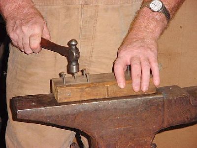
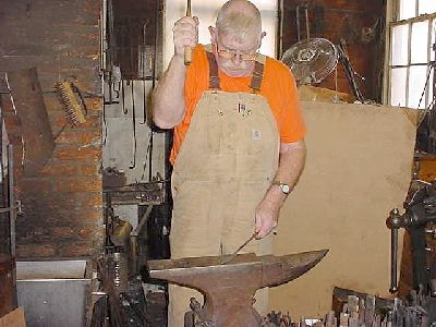
Now we come to the MOST IMPORTANT part of Smithing --HAMMER CONTROL. What is hammer control? This is the ability to HIT THE INTENDED SPOT each and every time with ACCURACY. You can obtain hammer control by practicing a simple exercise with a SMALL hammer till you get it right. You can build a very SIMPLE TRAINING AID, that will help you greatly in obtaining CONTROL of your hammer strooke.

Take 5 large nails and cut them in half with a saw and deburr the ends, then take a 2 by 4, XX inches long and drill 5 holes in each half about 5/8 inch deep, and a little smaller than the nail shanks, for a snug fit, and drive the nails in as shown.
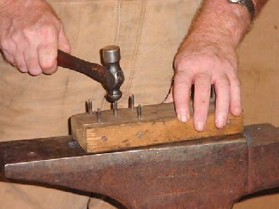
Using a small hammer with a small face practice tapping on the nail heads in a predetermined sequence till you can HIT the NAILS on the HEAD, each time, frequently changing the sequence.
When you get good at this procedure use the peen end of a small ball peen and work at TAPPING the SHARP ENDS with the BALL END, till you can hit it DEAD SQUARE so the ball doesn't glance off when tapping them, again in a predetermined sequence, and then changing the sequence often. I know it sounds like a waste of time, but its not that easy with the ball pein.
I know you all can drive nails with a nail hammer, so now its time to see if you can drive nails with a BLACKSMITHS HAMMER. Ok, I hear the grumbling, "WHAT'S SO HARD ABOUT DRIVING NAILS WITH A BLACKSMITHS HAMMER?" Well, try it and see if it's hard or not. Taking a scrap oak 2 by 4, start about 5 or 6 SMALL NAILS an inch apart in a row and pretending you are WORKING IRON on your anvil, raise a 1.5 or 2 lb BLACKSMITH hammer ABOVE YOUR EAR as you would do if you were working iron and try driving the nails with the SAME FORCE you would use WORKING IRON, and see if you can do it with out BENDING the nails OVER. When you get good at that, then start some nails in the board a 1/2 inch farther apart than your hammer head is wide, and TRY driving every other NAIL with the SAME FORCE you would use WORKING IRON (WITHOUT bending the intended target) or HITTING THE ONES ON EITHER SIDE. Now is the time to be glad the objects on either side are not FRESH EGGS. LOL

Now if you haven't decided to sell your anvil and hammers, and start looking for a job as a carpenter, now that you can drive nails, lets start looking at PREPARING YOUR BODY FOR HAMMERING.
Most of the time your arm is used for lifting, so the muscles that are the most developed are the ones used to LIFT your forearm. With Hammering you need to DEVELOP those muscles that will be swinging your hammer DOWNWARD. This is easily accomplished by setting at a table or in a chair with arms and making a fist and putting the heel of your hand on the table, or chair armrests and PUSHING DOWN and HOLDING it there for a count of 5, by repeating this EXERCISE 10 times and then RESTING your arm a bit. then repeating again like a body builder, you will strengthen those muscles that move your arm DOWN.
Another weak spot is your WRIST, most people don't use their wrists much, so they tend to be weak and easily injured. To STRENGTHEN your wrist, hold your FOREARM so that it is PARELLEL with the floor as if you had just FINISHED a blow with your hammer, and with a small 1 or 2 lb HAMMER held in your hand as mentioned above, FLEX your WRIST thru its FULL RANGE of motion UP and DOWN in repetions of 10, then rest it for a bit, do this for NO MORE than 30 times the first time and increase the repitions by 10 every couple of days. If your WRIST STARTS TO HURT, "STOP." PAIN means your wrist has HAD ENOUGH for awhile. GRADUALLY increasing the hammer size UP TO about 3 lbs will gradually increase your wrist strength.
ANYTIME YOU GET PAIN IN ANY PART OF YOUR ARM OR HAND WHILE HAMMERING, STOP, AND LET IT REST, and try to determine what you are DOING WRONG, that is CAUSING the PAIN.
Now that you are thoroughly CONFUSED or possibly ENLIGHTENED and can drive nails with a vengeance and ARM WRESTLE a GORILLA. Lets move on to ANVIL POSTURE. This is the part that can CAUSE INJURY to your BACK, ELBOW and SHOULDER.
If you must work HUNCHED OVER your anvil, remember in your GOLDEN YEARS, that you might have prevented all that BACK PAIN if you had wanted to. I have a bad back so I must stand up straight to do any work, as stooping causes PAIN.
TENDONITIS of the ELBOW, often referred to as tennis elbow, due to its common occurrence in tennis players, but in fact any sport or activity that requires GRIPPING can cause this problem. Tennis elbow occurs when their is DAMAGE to the muscles, tendons and ligaments around the elbow joint and forearm. Small tears, called micro tears, form in the tendons and muscles which CONTROL the movement of the forearm.
A THOROUGH WARM UP will help to prepare the muscles and tendons for any activity to come. WITHOUT a PROPER warm up, the muscles and tendons will be tight and stiff. There will be LIMITED blood flow to the forearm area, which will result in a lack of OXYGEN and nutrients for the muscles. This is a DEFINITE recipe for a muscle/ tendon INJURY.
Now you know why its IMPORTANT to start off making NAILS, "S" hooks or some other SMALL project.
Keep your SHOULDER, ELBOW and WRIST in a STRAIGHT LINE, with your elbow CLOSE to your BODY at all times.
Keep your arm in the same correlation while following thru with the hammer blow.

PAIN, in your Hand, Wrist, Arm or shoulder is a WARNING SIGNAL that something is not right and continuing will RESULT in some SERIOUS downtime. Pay ATTENTION to your body's warning signals, it will tell you when something is WRONG and needs to be CORRECTED.
I do something unconsciously, that I never realized till I started doing this Blueprint. The amount of FORCE that your hammer applies to the piece being worked is relative to the amount of VELOCITY with which your hammer DESCENDS toward its intended target. If you were to watch me in slow motion as I hammer, you would see a sort of POWER BOOST towards the end of my stroke, when I FLEX my wrist in a downward motion that adds speed to the hammer, thus increasing the VELOCITY and boosting the POWER at the last moment.
This is my favorite style of hammer, a right hand quarter pein.

This was one of my youngest uncles favorite plow hammer, It's just a little worn down. His son now owns the shop and I think has retired it as its a little hard on the knuckles.
This is a pile of the right hand 1/4 peen hammers I keep at the anvil for use, from top down, 2lb, 2.5 lb, 3 lb, 3.5 lb
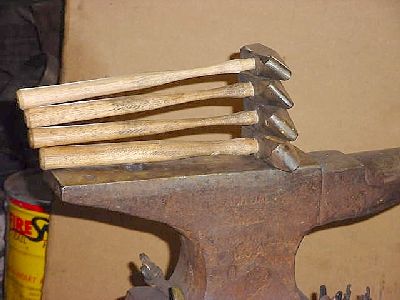
This is a squat 2.5 lb right hand quarter peen, I use for dinky jobs like 1/4 rod and such.
Well the long winded simple explanation is over. Let the controversy begin. If you don't agree with me, then you disagree. If you are not more confused, then you might be enlightened. If this helps you, that's good. If this keeps you from injuring yourself, that's even better. -
IForgeIron Blueprints
Copyright 2002 - 2011 IFORGEIRON, All rights reserved
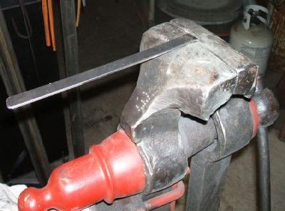
BP0345 Vise Grip Modifications
by Oakwood aka Jens Butler
Original idea by Don Butler
Ever try tightening a vice grip while wearing welding gloves? Doesn't work so well does it ? Or how about those Chinese knock off self locking pliers with the tiny mostly smooth knobs, those are almost impossible. A solution: weld a large washer or ring to the end ( be careful of the fumes the pliers are zinc coated ) If you suffer from carpal tunnel syndrome or use vice grips while welding or even have an unheated shop you know what I'm talking about. Also makes a vice grip into a useful tool for hauling sheet tin or other large awkward building materials on to roofs, just use 2 pair an a stout rope.
-
IForgeIron Blueprints
Copyright 2002 - 2011 IFORGEIRON, All rights reserved
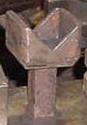
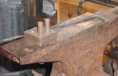
BP0346 Swage Block Alternatives
by Irnsrgn
This is an alternative to a big heavy and sometimes awkward Swage Block. This alternative makes a much lighter way of having bottom swages for demoing and you don't need another stand to take along for the swage block.
I used 2 inch square for my swages, so the first order of business is to make a swage holder that will fit into the hardy hole of my anvil. One holder and 4 small blocks gives me 12 different sized bottom swages. I have a Bridgeport Mill to make the swages with so it was fairly easy for me to make the blocks.
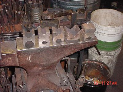
These are the swages and holder set out on my anvil. L to R , 1 1/4 and 1 1/2 round block, 3/8 - 1/2 - 5/8 - 3/4 round block, 7/8 and 1 round block, holder, 1/4 - 3/8 - 1/2 - 3/4 square block.
This is another base 3 1/2 inches square with a hardy shank on it to hold short pieces of Oak 4 by 4 which can have depressions in both ends for spoons and such if desired, 1 or more short blocks do not weigh much either and can be carried easily.
-
IForgeIron Blueprints
Copyright 2002 - 2011 IFORGEIRON, All rights reserved
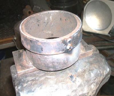
BP0350 Flux Container
by Oakwood aka Jens Butler
Spill proof super duper flux applicator.
Requires: One clean and dry water bottle or bike bottle with the squirt top. Fill with borax, pop squirt cap up to apply borax to pieces to be welded, squeeze or shake as needed. Pop cap closed to store and keep moisture levels low and dirt/ bugs out. No lids to forget, no spoon to loose, no box to spill when it gets knocked over.
-
IForgeIron Blueprints
Copyright 2002 - 2011 IFORGEIRON, All rights reserved
BP0319 Trig for Blacksmiths
by Strine
Insert Pix 1
Trigonometry is based on a right angle triangle where the hypotenuse i.e. the long side of the triangle is the radius of a circle and is equal to one unit, eg 1 metre, 1 foot, 1 banana skin. That’s why it’s called “The Unit Circle”. Values are obtained for the mythical/mystifying “sin” and “cos” and “tan”, properly known as sine, cosine and tangent, are merely the lengths of the sides in metres, feet or banana skins depending on the unit you are working with.
When you enter the angle Z into a calculator and press the “sin” button or look up the value in a log book you get the length BC of the triangle. Similarly cos Z is the length AC and tan Z is the length DE.
Now when you are pitching a roof or cutting a piece of plate the hypotenuse is rarely 1 unit but your triangle is relative in size so all that needs to be done is scale up the sin cos tan values accordingly.
In short “Trigonometry” is nothing more than the manipulation of a simple right angled triangle. Your triangle might be topsy turvy or back to front but if it has a right angle in it Trig will get you home every time.
One last point; to calculate all the unknowns in a triangle you must have at least three bits of information one of which must be a length, and of course it’s OK to revert to Pythagoras when ever you have enough info. -
IForgeIron Blueprints
Copyright 2002 - 2011 IFORGEIRON, All rights reserved
BP0324 Find the Radius of a Circle
by Jim Carothers, Glenn Conner
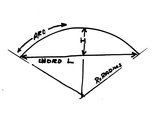
This is the standard set up for a circle where R= radius, L = cord length, H= maximum distance from L to the arc
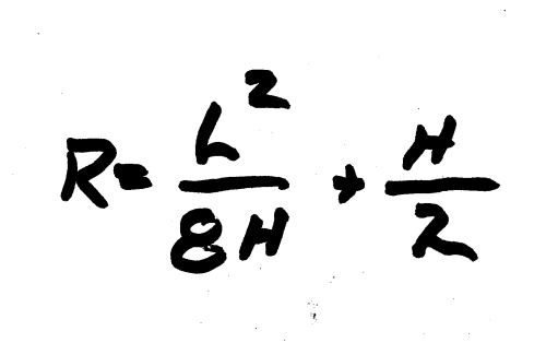
To find R (radius of the circle) divide the length of the cord squared by 8 times the maxumin height from the cord to the arc then add 1/2 the maxumin height from the cord to the arc.
I like the old time formula, 1/2 L² + H² divided by H = diameter. Irnsrgn -
IForgeIron Blueprints
Copyright 2002 - 2011 IFORGEIRON, All rights reserved
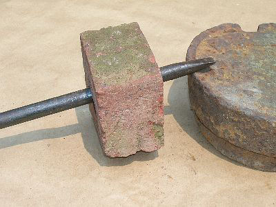
BP0363 Cracking a Nut
by Glenn Conner

This piece of auto part was 3/4 inch in diameter, just what I thought I needed for a project.
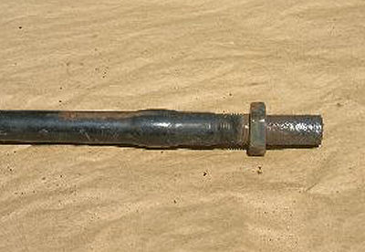
But there was a nut on the end that would not be removed.

The threads were really messed up and I needed the whole length of the material for forging.
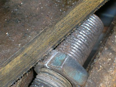
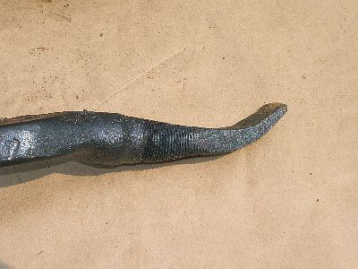
So with a hacksaw, you just cut into one of the flats of the nut, being careful not to cut into the threads.
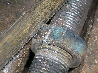
Then cut the opposite flat being careful not to cut into the threads.

The cut is almost to the threads.

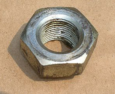
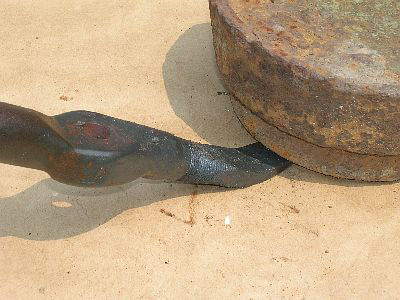
With a chisel, expand one cut and split the nut.

The second cut will give the nut room to expand and come apart.

And the nut will drop off the bolt with the threads still in good condition.
-
IForgeIron Blueprints
Copyright 2002 - 2011 IFORGEIRON, All rights reserved
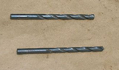
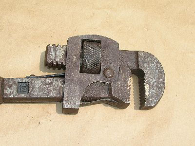
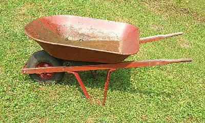
BP0362 Simple Tools
by Glenn Conner
There was a discussion on the IForgeIron forum about what would be good tools for material handling in a shop. This got me to thinking about the simple tools we use every day without giving a second thought to their function.

The wheel comes to mind first. If it is on a car, truck or two wheel dolly, the rotational motion is the same, it makes moving heavy things easier by rolling. The same is true for putting pipe under an object to roll on.

The incline plane, a board from one level to another to roll up or down. You can even "walk" a heavy object up from floor level to table level on a incline plane. The screw is an incline plane only in a spiral.
And it does not have to be an outside incline plane, but it could be inside in configuration.

We use the screw in several different ways. To clamp.
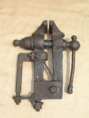
Ok to keep it blacksmithing related, to clamp.
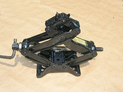
To lift.
Ok to keep it blacksmithing related, to lift.
This also uses the wedge to scrape and remove a small amount of surface.
To adjust clamping size, then use wedges to grip and a lever to move along the incline plane, such as bolts or threads on a pipe.
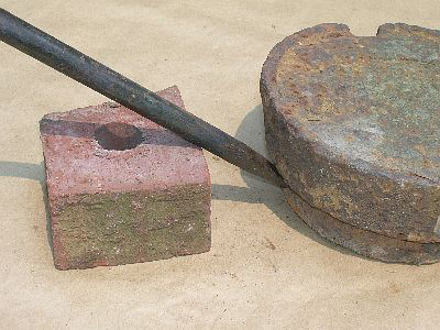
Everyone knows about the pinch bar, or lever. Add a fulcrum and you can move a lot of weight with little effort.
But you can also use the lever to lift.
If you combine the lever with a fulcrum you have the best of both.
You have the fulcrum built right into the lever.
This is no more than a specialty lever.
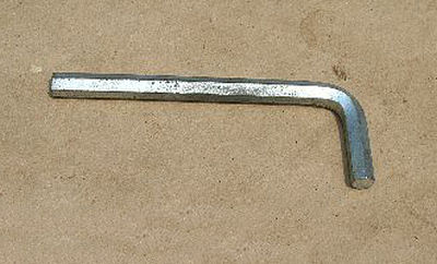
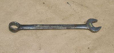
Another specialty lever. This for a hex socket head bolt.
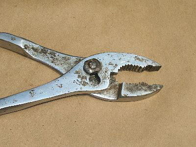
This is just another lever but with an adjustment for size of the gripping end.
Another simple lever, but with an adjustable gripping end.

And we call it a binder, but it is just a lever in disguise.
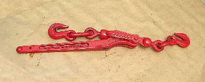
In the closed position.
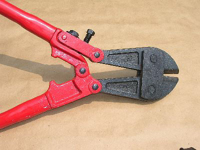
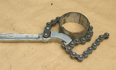
And there are those tools that incorporate a double lever for more power. This also uses a wedge to make the tool work.
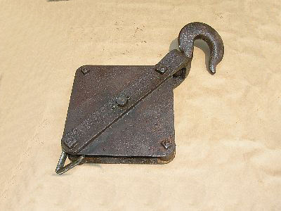
Back to the wheel, only now called a pulley. You can use these wheels to change the direction and change the speed of the pull.

They come in several sizes to fit your needs.
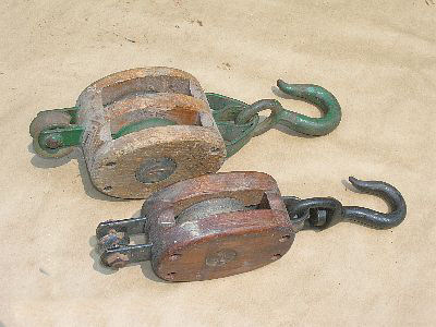
And when you combine two or more pulleys, you can multiply your power. But you have to figure out how to string the rope through them properly.
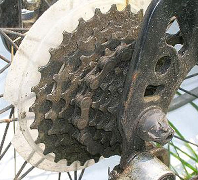
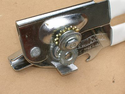
Another specialty wheel is a gear, sort of like pulleys with teeth for chain here, or with matching teeth as in a manual transmission.
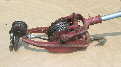
But the wheel and teeth do not have to be complicated in order to multiple power. This is rated for 4000 pounds of pull. Again you have to know how to set it up to get the multiplication of power.
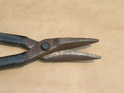
We can combine levers and wedges to cut.
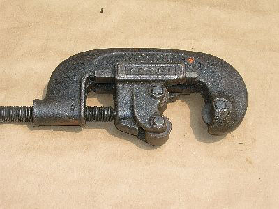
We can combine screws and wedges to cut even heavier material.

And we can combine crease and wedges to cut in special applications.
Ok, that was a little unfair as some have not looked at these things that closely.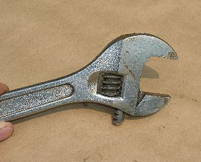
You can combine screws and levers.

You can combine levers and hydraulics.

Levers and hydraulics again.
And levers and wheels.
We use simple machines, and combine simple machines, to make tools to get the job done. Each is a speciality item (or so the sales pitch tells us) but is just a varation on a theme. Stop looking for the answers and start seeing the possibilities. It is not rocket science and you don't have to reinvent the wheel.

Or you may want to use the screw to measure with. <grin>
-
IForgeIron Blueprints
Copyright 2002 - 2011 IFORGEIRON, All rights reserved
BP0398 Christmas Light Tool
by Jerry Carroll
If you have a couple of the mini bulbs that need replacing after the lights are up and you don't have enough finger nail left from chewing them while shopping with Momma, here's a helper. Merry Christmas!!

Stuff needed to make the light pulling tool. I used a 10" hacksaw blade, any size will do.

You can break the ends cold & lightly hammer to make them flat. To get the bends you gotta use the heat (propane torch) or it will break, just red enough to bend and you won't have to harden. After bending the ends to suit you (not over a 1/4 inch long), heat and bend at the middle so the ends are matched up.
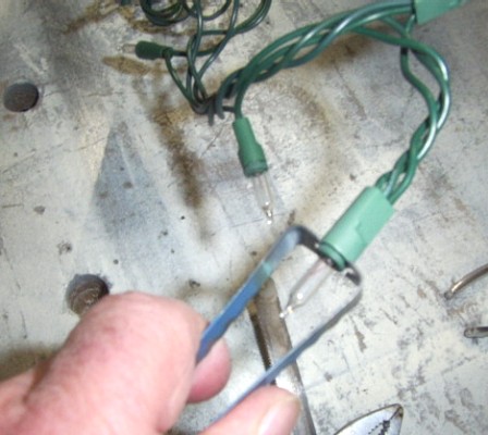
Grasp the bulb at the flange and wiggle easy while pulling. TURN OFF THE ELECTRIC or unplug the light before removing the bulb.
-
IForgeIron Blueprints
Copyright 2002 - 2011 IFORGEIRON, All rights reserved
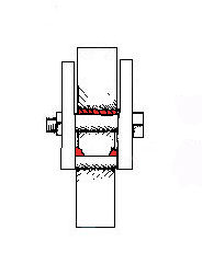
BP0378 Horse Shoe Nail - Spoon Making Jig
by Mr Smith of Oz
Start by making the tool to do the work.

The whole thing is or can be made from one piece of flat bar, except for the hinge, bearing and hardy shank. (Ours is roughly 20mm x 6mm). Weld (as indicated by red) carefully so as not to have the weld damage the edges of the hardy hole.
Weld (as indicated by red

The "business end" is where you'll have the most trouble. You weld in a ball bearing, or substitute a nut and bolt, then round off the bolt head."
Once you have the upper part taken care of, heat the bottom part and hammer the top part down creating a DIMPLE or impression. TA DA...you have just created a miniature top and bottom swage tool!!
The whole upper should be balanced, so that when it is lifted up it will stay up.
Take a #7 horse shoe nail and flatten the head as shown.
-
IForgeIron Blueprints
Copyright 2002 - 2011 IFORGEIRON, All rights reserved
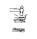
BP0376 Bending to ID Dimension
by Irnsrgn
After making the first bend, mark the inside dimension desired and put a center punch mark or nick.

Line the mark up with the edge of the mandrel you are using and bend, then cut the bent end to length desired.
The results, this works every time to get a predetermined inside measurement. I started using this procedure with a hossfeld bender 50+ years ago. Works hot or cold, but when bending hot, you must localize the heat or it will bow when you bend it. -
IForgeIron Blueprints
Copyright 2002 - 2011 IFORGEIRON, All rights reserved
BP0384 Using Coal Fines
by Glenn Conner
There has been some discussion of how to deal with fine coal, coal dust, etc. There was a coal truck headed for a power plant that tipped over and I was able to get some of the coal. Turns out it works for forging but only if you separate the lumps from the fines.

The lumps are heavy with rocks that just do not burn well.
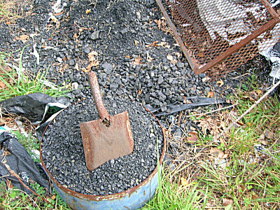
If you shift it through expanded wire you get the lumps on the left and the fines in the tub. You just shovel the fines into a 5 gallon bucket so it is easily carried to the forge for use.
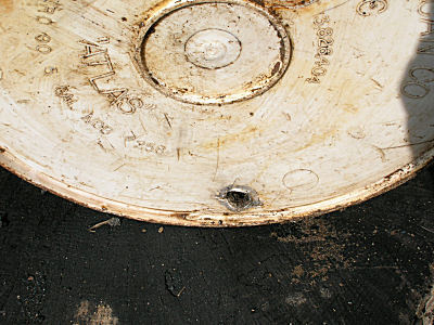
With a hot rod, I burned a hole into the bottom of a plastic bucket. This allows for any water to drain out.
The bucket keeps the coal rather moist.
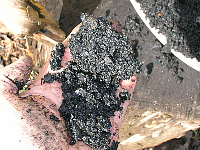
When you squeeze the coal fines, it should clump together. Otherwise add more water to the bucket and allow the excess to drain off.

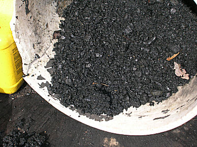
How wet? This is the 2nd bucket of fines waiting to be moved over to the forge.
One word of caution, during cold weather the moisture (wetness) in the coal fines tends to freeze. This is when the fines are allowed to dry out and water is added just before it is used in the forge. The water is NOT put in the forge, just the moist (damp) coal.
This damp coal cokes up nicely leaving a dome of coal with a hollow inside. Just push the green coal into the fire from the front opening, keeping the dome in place. For me, this tends to act as a oven and heats the metal a little more efficently. I keep the hollow small because it is the heat of the coals that transfer the heat to the metal, not the air inside the hollow.
-
IForgeIron Blueprints
Copyright 2002 - 2011 IFORGEIRON, All rights reserved
BP0380 Shop Beverage Holder
by Richard Thibeau
A simple, but very convenient shop accessory which will keep you favorite beverage out of the way while you work, yet readily available when necessary.
The item is made from only two pieces of steel. In this case, ¾” x 1/8” strapping was used, one 11” long, the other 13” long. Almost any size can be used, round or flat or square, as long as the final inside dimensions are greater than the can or bottle you wish to hold.
The basic tools needed are a vise, scrolling pliers, and a jig which is a piece of 3 inch diameter pipe welded to angle iron to be held in the vise.
The first piece of material is marked off for later bending. For a typical can or bottle, the first mark is 3 inches from one end, the second mark is at 6 inches, and the third is at 9.
Place the piece in the vise to the depth of the first mark, bend 90 degrees

Place the piece in the vise to the depth of the second mark, bend 90 degrees. Straighten the piece out so that both bends are actually 90 degrees.
Using the scrolling pliers, bend the second piece around the pipe jig and tack weld the ends together. This bend is done cold depending on the size of the material being used.
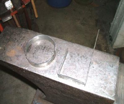
The two pieces ready for assembly.
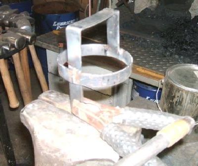
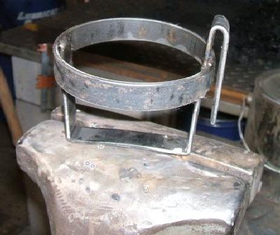
Place the first piece upside down in the vise, slide the second piece over it, use vise grips to hold them in place, and tack weld together. Finish welding and clean up the welds. The piece is now assembled. Rivets could be used instead of welding, there are only two points to connect. Bend the upright of the first piece to fit where you plan to hang it. In this case on the hammer rack which is thin flat stock.
Test the fit. It’s almost completed.
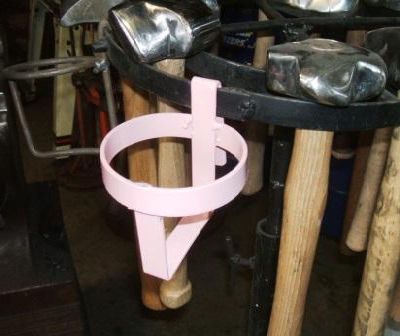
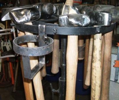
With the appropriate finish applied, it is now completed and ready for use. A proper color will enable you to always find it in a moment. -
IForgeIron Blueprints
Copyright 2002 - 2011 IFORGEIRON, All rights reserved
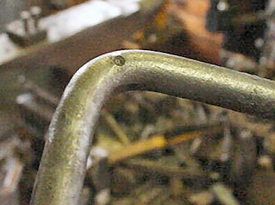
BP0309 Car Radiator Clamp Holder
by Jim Carothers
Saturday afternoon I put all new hoses on my wife's Chevy. I had a real hard time getting the factory GM spring band type clamps off and back on. I like the way these clamps work -- nice even tension on the hose / joint. I don't like working with them. There are special tools for these clamps; but they are expensive, and not available on Saturday afternoon in Perry, OK. I only have to do this about every 100, 000 miles.
Getting the clamps back on was the hardest part. I finally got down to one last clamp -- the big one on the bottom of the lower radiator hose. There was just no room to get any of the 7 different pliers I have in there to squeeze the clamp to open it. If I could get a squeeze on the ears, it was not enough to fully open this large (2") clamp and get it up onto the hose.After about an hour working on this one last clamp, I changed projects (took a break and went to see my farrier neighbor). The idea of squeezing the clamp out of the vehicle and holding it open with a piece of wire occurred to me upon returning to the Chevy. I am likely not the only person to think of this; but working alone, it was almost a revelation to me. I had the hose on and the clamp positioned easily in a few minutes. Cutting the wire finished up the job.
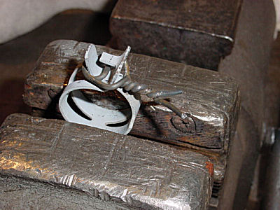
The clamp in the photo is a small clamp used on the heater hoses, but serves OK as an illustration.
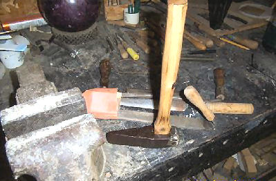
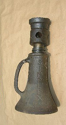
BP0331 Brake Piston Press
in BP 300 Series
Posted
IForgeIron Blueprints


Copyright 2002 - 2011 IFORGEIRON, All rights reserved
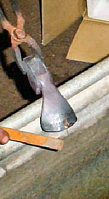
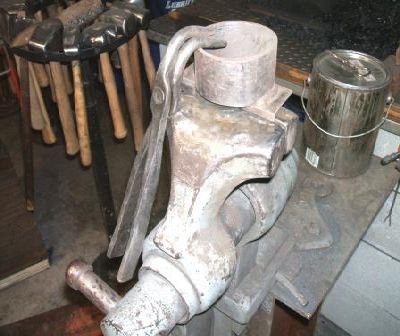
BP0331 Brake Piston Press
by Glenn Conner
WARNING, using this tool and method on new cars with ABS Anti Breaking System can damage the ABS system..
On many of the older cars, when you replace the brake pads, you must force the hydraulic cylinder back into the caliper to have room to insert the new brake pads. The local garage mechanic was always fussing about this part of the break job.
I "borrowed" an old leaf spring from the garage. At the forge I cut it to length, and rounded one edge to somewhat match the inside of the caliper. The bolt fits easily into the open side of the calipers and when turned presses against the hydraulic cylinder of the caliper moving it back into the caliper, making room for the new break pads.
Below the leaf spring is just a nut welded to the spring. A piece of 3/8" rod is welded to the top of the bolt for a handle and leverage. I used this handle on the top of the bolt instead of leaving the bolt head as is, so there would be no reason to use a air wrench to move the hydraulic cylinder and damage the caliper. Slow is the way to go in this case.