

Steve Sells
-
Posts
9,162 -
Joined
-
Last visited
Content Type
Profiles
Forums
Articles
Gallery
Downloads
Events
Posts posted by Steve Sells
-
-
BP 202 Cleaning up the shop
By Glenn Conner Copyright 2019
IForgeIron Blueprints Copyright 2002 - 2019 IFORGEIRON, All rights reserved.
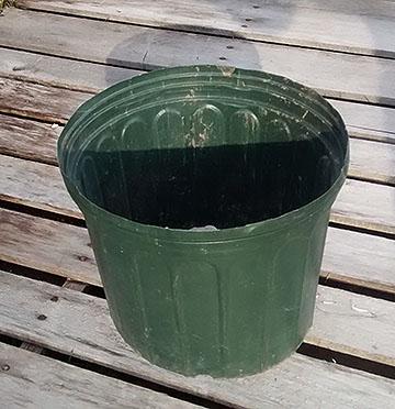
Trying to keep the shop a bit cleaner.
Start with a plastic flower pot 11 inches diameter at the top, from the garden center.
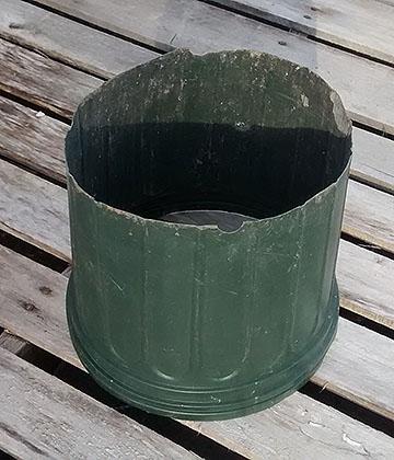
Cut off the bottom.
Insert a plastic grocery bag into the pot and over the top edge.
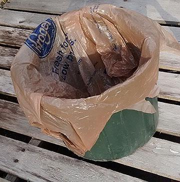
As debris is collected, put it into the pot.
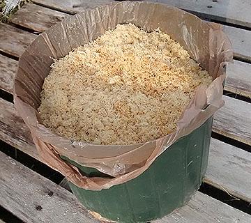
When the pot is full, tie the bag closed and lift the pot. The bag will slide out the open bottom. Throw the bag of debris away.
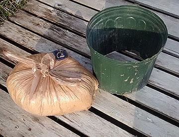
The pot keeps the bag open. Insert a new bag and start cleaning again.
It is surprising how much stuff you can dispose of a small quantity at a time.
Edited by Glenn
-
slowly getting them moved over, so far I have 00, 100, 300 series moved into the forum and they can be commented on now as well. I dont have photos for 200 or 500 series yet still searching for them, we have them somewhere I think
-
IForgeIron Blueprints
Copyright 2002 - 2011 IFORGEIRON, All rights reserved
BP0301 Tulips and Vase
by J.W.Bennett (JWBIRONWORKS)

This is how I make a vase full of tulips.

Stock list:
2 - 1/4"x14" round stock
1 - 1/4"x12" round stock
2 - large tulip blank 16 ga
1 - small tulip blank 16 ga
1 - 1-1/2" sch 40 black pipe 10" long
3 - 1-1/4"x1 1/4"x1/8" angle iron 12" long

Using the patterns above cut your 2 large and 1 small tulip blanks. I list 16 gauge, but I use whatever sheet stock I have on hand that is close. Lay these to one side.

Take your three pieces of 1/4 round stock (RS) and slightly neck down one end about 1/2" back to form a pistil I believe it’s called. Also, beat it up a little for about 4" worth to add texture.

When you’re done they should look something like this:

Clamp one of the 1/4"x14" RS piece in the vise and tack weld one of the large tulip blanks to the end you just formed the pistil on. I try to place the pistil end on an imaginary line drawn between the two dips in the blank and centered down the middle of the blank.
If you make too large of a tack weld it will be hard to close the bottom later on and if you don't get a good enough tack the blank will come loose as you close it. I have done both several times.

Repeat with the other 14" RS and large tulip blank and the 12" RS and the small tulip blank. If you weld the wrong blank to the wrong round stock don't sweat it. It just means that when you arrange the finished flowers in the vase that the small tulip will set up with a large tulip. I have done it both ways. This is what you should have now.

This is a tool from Jr. Strasil’s bag of tricks that I made. It works real well to fold the tulip leaves over. Basically, it is a piece of 2"x1/4" angle welded to a hardy and tapered. I have used this tool for countless things since I made it. Thanks Jr.

Take one of your tulips and heat it to a red/orange heat and lay it pistil up on the tool. Using the straight pein of the hammer, work the edges up and around. Work from the bottom up and don't work the ends so much that they get in each other’s way.

At this point I take another heat and then, using the flat face or a slightly rounded face hammer, I finish closing the tulip up. Try not to work it too cold that way you don't mark it up.

At this point I usually have a tulip that looks like this:
Slip the tulip over the horn of the anvil and round it out and get the spread that you want across the front.
It should now look something like this:

Take another heat and roll the edges of the tulip over on the backside of the anvil. Try to get a nice flowing roll, repeat this on the two front edges (lobes) also.
Finish rolling the edges to your liking. I like mine about a 3/4 roll but it's strictly up to personal taste.

This shot shows the three stages so far, right to left.

This is the layout for the leaves on the 1 1/4"x1 1/4"x1/8" angle iron. The top piece is one cut and ground. You will need 3 of these.
Heat the beveled end to a red/orange heat, lay it on the anvil ^ center up and spread it out. Do not flatten it out completely. You want to end up with a gentle open effect.

Now take another heat and lay it open side up over the back side of the anvil. With the face of the hammer work a bending curve in the top half of the leaf. Work this gently or you will mar the rib on the back side and kink it.

Your leaves should look something like this now.

Clamp the bottom of the stem in the vise. Place the bottom of the leaf 4" up from the bottom of the stem and clamp it to the stem. Tack weld it 3" up from the bottom edge of the leaf. If you tack it at the very bottom you will have problems rolling it up in the next step.

This is what you should have now. The bottom stem length on this photo is a little long so if yours are shorter don't worry about it.
Take a good orange heat on the bottom of the leaf.

Roll one side of the bottom 3" to 4" over as shown.
Take another heat and roll the other side over and continue turning it on the anvil and rolling it up working always in the same direction until you get a good tight roll. This will make placing them in the vase a lot easier.
Repeat with the other two leaves and stems then set them aside.
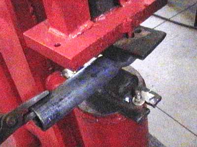
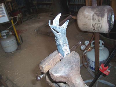
Measure approximately 3 1/2" up from one end of the 1-1/2" black pipe. Mark it and then heat to a good orange heat and fuller/neck it down to approximately half the starting diameter. I used a power hammer. I have also used a smithing magician. Never tried to do one with a fuller on the anvil but I'm sure it's possible.

Take another good heat and using the horn of the anvil flare the end you just fullered. After I have flared it out a bit, I take an adjustable wrench with all the sharp corners/edges ground off and I finish the flare almost straight out.

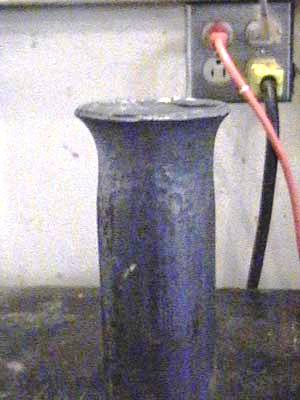
Place the top end on the anvil and true up what will be the bottom of the vase.

True up the bottom diameter by heating the bottom to a good hot orange heat and driving it on to the anvil horn while rotating the vase. You will probably have to repeat the last two steps several times to get the vase to set level and straight.

You should have something like this now.
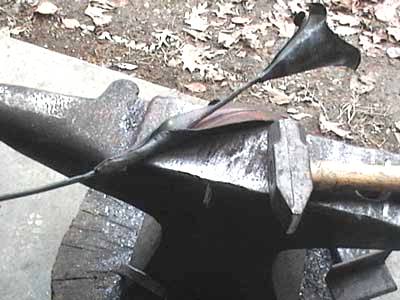
Now take a good orange heat on the other end of your vase. Once again, working on the horn of the anvil, flare the top of pipe out. I use a combination of the straight pein and a round face hammer for this.

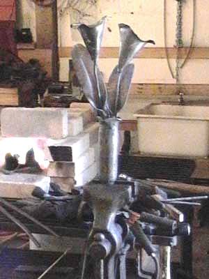
So far, so good. Flare it to your personal taste. At this point you can leave it flared. I decided I wanted to waffle or scallop the top, so I did an extra step or two.
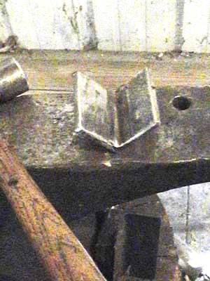
Using another version of the angle iron swage used earlier, I took another good orange heat on the top of the vase and then laying the flare in the angle V I set it down with the straight pein on 4 equal (more or less) points.

I like the profile that gives.

Now comes the fun part: Stuffing all three flowers in the vase.
Play with them first and get them half way arranged the way you want and then tack them to the vase one at a time.
They are easier to arrange in a vase made of 2" schedule 40 pipe, but I personally like the looks of the 1-1/2" better.
This is how I do it and then I polish and texture to finish. I'm sure there are short cuts and easier ways, but this is one way to do it and I hope you find this useful.
JWB -
IForgeIron Blueprints
Copyright 2002 - 2011 IFORGEIRON, All rights reserved
BP0302 Eternity Rose
by John Jobe aka jj2k

Start with a 1” square tube, 1-1/4” square tube, two leaves and an 18” piece of ¼” round.

Cut 45 degree cuts in each of the 4 sides.

In the 1” square tube on one side cut the angled cut half way into one of the next side.

Taper one end of the ¼” round and texture for stem

Forge the end of each tube on the horn as shown

Texture each petal as shown
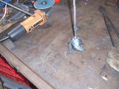
Using a sanding disc on your angle grinder, grind away the point and round the top of the petal.

About ½” back from the cuts, fuller the tubes down to a stem size. Maintain your bell shape on the horn as you go, it will make things much easier.

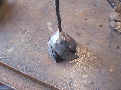
On the 1” tube, on the side we cut half way into the next side, use your scroll pliers to wind this piece up and then center it over the middle of the bud pulling up toward the top as you go.

Close up the bud hammering down and around on each remaining petal. Use a swage block or a half round swage of some sort to keep the roundness in the bud.

Cut off the 1” bud and weld it to the stem.
Cut off the 1-1/4” piece and while holding the stem and bud upside down on the table, slide the other piece over this bud and weld it in place.
Clean up your weld while being careful not to get into the stem.

Wrap up the new piece around the bud.

Using your scrolling pliers roll the top edges outward as shown.

Start a scroll on the base of the stem and then finish the scroll.
Make minor adjustments to the rose. And weld on the leaves. You can heat up those welds and hammer them to blend into the stem. Polish with a wire wheel and shoot clear. This Eternity Rose was donated to Habitat For Humanity for their fundraiser and will be in the silent auction. -
IForgeIron Blueprints
Copyright 2002 - 2011 IFORGEIRON, All rights reserved
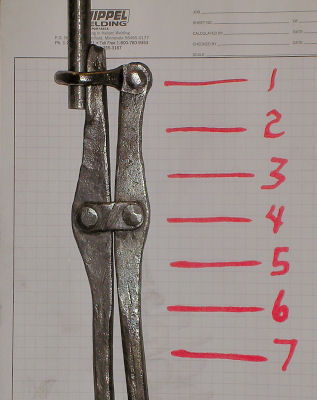
BP0303 Swivel Link Universal Tongs
by Jeremy Knippel
These tongs were seen in the "British Artists Blacksmith Association" magazine winter 2005 #115. They are similar to a pair that belonged to Hector Cole in the article by Graham Robinson. Giving credit where it is due.
I had never seen anything like these so I tried to make a set just for giggles. This way my first set of tongs that I made and with the exception of burning one half of the tongs a bit (not to bad) all pieces were only made once.Grip range for these tongs are 3/8" to 5/8" round but tapers and squares can be held also.
List of materials:
2 pieces 3/16" x 1" x 17"
2 pieces 1/4" x 1/2" stock
1 piece 5/16" round 16" - 20" in length. Long enough so you don't have to use tongs to hold it
All rivets use a 3/16" hole
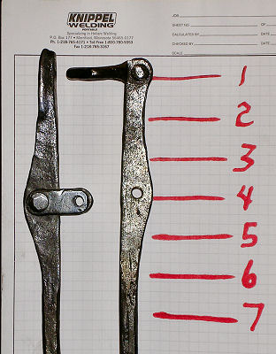
Forge top of the tongs with one of the 3/16" x 1" flats to shape and punch 3/16" holes for the rivets on 3" centers and draw reins out to the desired length.


Forge lower part of the tongs. Upset the end of the 3/16" x 1" to 3/8"tall x 5/16" wide for approximately 1-1/2 - 2". Form the rivet area, chisel and upset on the 5/16" area length wise for the length of the upset area to form a "V" to hold the stock. Draw out the reins to the desired length.


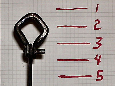
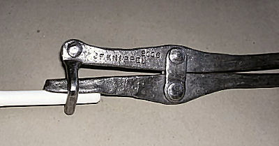
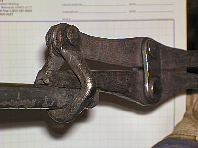
Forge the ring loop. Upset the 5/16" rod on end for approximately 1/2" - 3/4" to a finished size of 3/8" to 7/16" for the rivet tab. Cool with water to localize the heat. Measure from the end 4-3/4" and hot cut. Repeat upsetting on this end also. Total finished length should be approximately 4-5/8". Heat the ends and flatten for 1/2" on edge of the anvil. These will be the rivet tabs. Flatten to approximately 1/8" thick. Heat and bend in the middle and form the ends. Drill holes for the rivets.
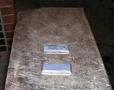
Take a piece of stock that is 1/4" x 1/2" and mash it to approximately 3/16 x 5/8". Hot cut them to 1-1/2" long and punch the rivet holes

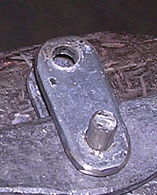
Rivet loop on to the top half of the tongs. The loop must swivel loosely.


Rivet the side pieces to the bottom side of the tongs. This rivet is to be tight with no movement.
Assemble both tong halves. Make sure the bottom is through the loop before riveting. If not you may have to grind the bottom end off to get the loop in place. Mine had plenty of clearance to swing around the end. The top rivet is the active connection.

Adjust the reins as usual to your liking and make any other slight adjustments.
The total length for my tongs was 19" Adjust to your personal preference.
-
IForgeIron Blueprints
Copyright 2002 - 2011 IFORGEIRON, All rights reserved
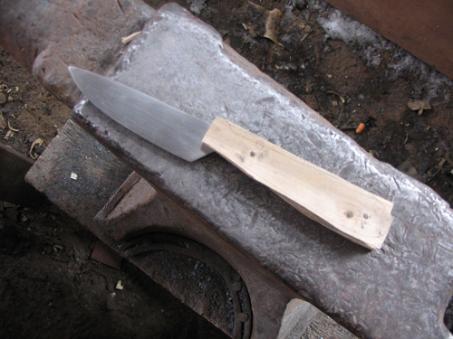
BP0305 Knife Sides
by Dennis
This is day two of our little knife making demo. Yesterday we closed with the knife ready to be normalized. This process in it basic form involves three cycles minimum of heating the blade up a little hotter than non-magnetic and holding it there, followed by letting it cool slowly. If the blade bends at all during this process, straighten it and then start the count over. If you get to the third heat and it is still straight when it has cooled, it shouldn't bend when you quench it (unless your quenchent is too cool--if the blade warps on quench, anneal it, straighten it at a red heat, and start the normalizing process over, and warm up your quenchent this time. I got lucky, it went through the normalizing process without warping--this is why it was important to only work your blade at an orange or slightly cooler heat. You don't over stress the steel when working it, it shouldn't warp when you normalize it. While normalizing the blade I worked on the scales for the handle.
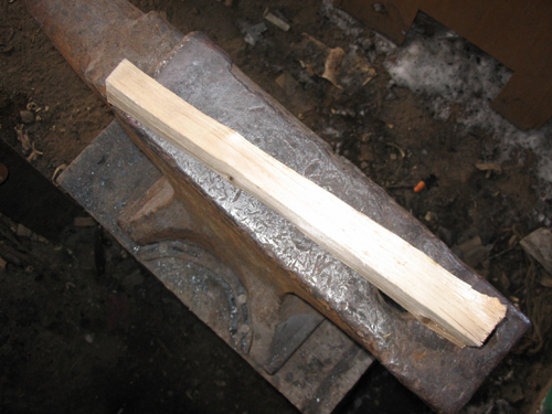
For the scales I used a piece of nice and seasoned maple that I found while splitting wood the other day. I was able to get a few hammer handles out of it, but this one was a bit narrow. I split this into three sections.
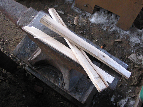
I should be able to get three or four knife handles out of these. They split nice an straight, far too straight for the wood stove.

I selected a medium thick (how thick, didn't measure, just picked one that looked "right") and smoothed down one side with a draw knife.

I measured the knife handle and gave myself about an extra 1/2 inch when I cut the scales.

Next, I cleaned up the side that faces the handle with a bit of sand paper, making sure to keep them flat while sanding. The rough side facing up will be cleaned up with a rasp in a bit.

Check regularly against a straight edge, when the daylight between the scale and the straight edge disappears, you're good.

With rasp and coarse sandpaper we're ready to start shaping the scales.

Secure the scale and start truing up the face with the coarse side of the rasp, you can clean up the rough surface of the scale with the fine side of the file. Try to maintain an even thickness across the piece.

When the blade has cooled after the final normalization heat, sand the surface with coarse sand paper and clamp down. We will now draw file the cutting edge.
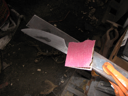
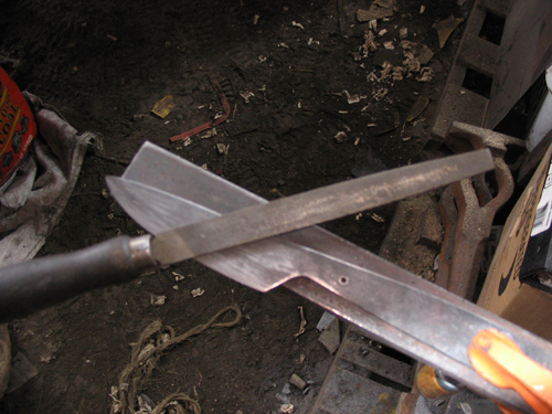
We will use the fine mill file from earlier. We will be blending the edge into the body of the blade and cleaning up any pitting that may have occurred due to oxidization while normalizing the blade. You can minimize the oxidization by maintaining a deep fire and being gentle with the air.
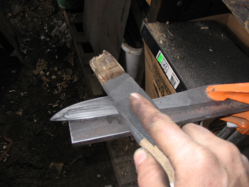
Once you have cleaned up any of the large scratches or oxidization pits begin sanding the blade with 220 wet/dry paper. Note the direction of the blade vs. where my hand is while sanding. You now have a blade that can cut you if you are not careful. At this point the blade is ready to be hardened. Heat it just a bit hotter than non-magnetic and quench. I have a magnet handing on a piece of string that I can lower down to forge level, and then back up out of the way when it's not needed. Learn the color of non-magnetic for the steel that you are working with. When you reach that temp quench the blade in warm oil (about 140F for 5160). Do not use your "meat" thermometer, oil can be very hot and look as if it was just poured from the bottle, DO NOT PUT YOUR FINGERS IN IT TO SEE IF IT IS WARM! I use vegetable oil, it's cheap and if it splatters you you'll smell like a deep fry cook instead of an oil refinery.

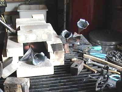
After quenching sand any scale off with 220 and proceed to temper. For the handle to blade transition I like to temper to a deep blue, for the blade I temper to a light straw yellow at the cutting edge to a dark straw yellow at the spine, maybe approaching blue. You can temper the blade over the blue flame of a gas stove such as a coleman propane burner or as I did, over the blue flames of a hot charcoal fire in the forge as in the picture above.

Here is an attempt at a picture of the blade after the tempering. The flash kept screwing with the colors.

The colors that form as you temper the blade are the result of oxidization and are easily sanded off. At this point we are ready to start attaching the scales. I cut it a bit close when I split the maple for the scales. As a reminder to myself as to what side is what, I like to trace the handle onto the scale on the side of the scale that faces in (that is, the side of the scale that is in contact with the metal).

First clamp a scale to the knife, and drill the holes. You should have the scale firmly down on a surface that you are not afraid to drill into. This prevents splinters from forming as the drill bit penetrates the scale.

We will use brass pins to rivet the scales onto the handle. I used brazing rod for the pins.

If not we have problems. Place the second scale on the other side of the handle, line it up and clamp. Next remove the rivets, being careful not to move the scales. Now drill through the the first scale and handle into the second scale.
To drill the holes in the second scale, place the rivets into the holes of the first scale so they stick out just a bit and then place it on the handle, the rivets should line up with the holes that we just drill

Replace the rivets and drive them through the scales.

Next trim the rivets and file them down to about 1/16" above the surface of the scale. If possible try to file them with a bit of a dome, to prevent the rivet's head from splitting as you peen them. I find that supporting the scale on the reverse side with a piece of metal the same thickness as the distance that the rivet protrudes. This prevents the scales from moving or sliding down the rivet if you happen to miss with the hammer.
With the rivets set, you are now ready to rasp the scales to shape.

Now clean it up with a bit of 120 followed by 220. Trim the scales at the blade to handle transition and you've got a knife.

The finished knife, ready to be stained or treated as you wish.
If you cut and file your bronze rod to length and take them one at a time and heat the very end red then quench in water it makes them dead soft and they brad down easier
Irnsrgn
I'd like to add one thing to the knife BP when drilling through the scales clamp the blade and scale to a piece of wood to prevent tear out when you drill through.
Oakwood
-
IForgeIron Blueprints
Copyright 2002 - 2011 IFORGEIRON, All rights reserved
BP0306 Saddle Cut
by Habu aka Mike Mcginty
Take a wide rubber band and a hand full of finish nails. put the rubber band around the pipe and place the nails evenly around the pipe, under the band, with the points sticking out as far out as you can. place the other pipe on top of the nails and push down gently at the proper angle.The nails will contact the cross pipe and automaticly lay out both the male and female side of the cuts. Draw around the nails with a silver pencil,cut and weld.
-
IForgeIron Blueprints
Copyright 2002 - 2011 IFORGEIRON, All rights reserved
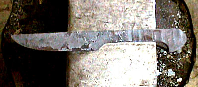
BP0307 Rail Road Spike Knife
by Jim Hrisoulas
© Jim Hrisoulas 2005 Used with permission
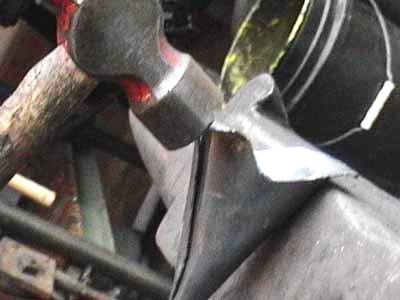
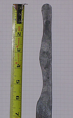
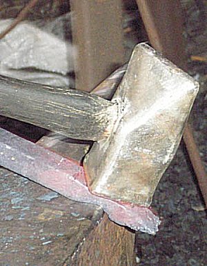
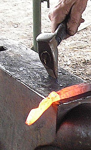
Carefully flatten head section and "blend" it into the start of the spike and continue to flatten this out until you have a flat area about 4" long.
The spike is flattened, starting from the head and then working down the spike shaft. This will be the gripping area.

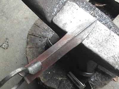
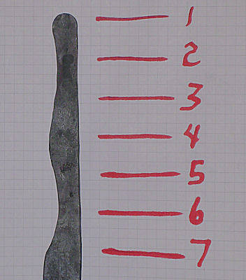
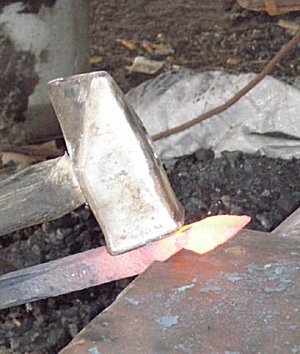
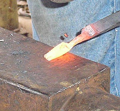
When this is done, flatten and spread the remaining shaft to form the blade. It doesn't look like there is much material there to make a blade more than a couple of inches long but there is. The blade is forged flat and is widened and drawn out into a rough forged shape
Once this area is flattened and drawn out the thickness is checked for uniformity and overall "blending" of the head and grip area.
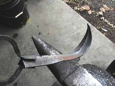
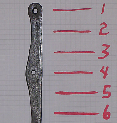
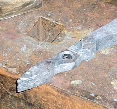
Working from the tip back, start to flatten and spread the blade. Widen as you go and then start in on the distal taper. When you get to the ricasso end, carefully widen this area and make sure the whole forging "blends" well into the shape you want. After the blade is forged out and shaped into the rough shape of what you want to make, this rough forging still needs to be profiled to final shape. Note: at this point the edge bevels have been formed ("packed") and the knife is pretty much in its final cross section. Now is the time to do any refinements and make certain that there are no drastic changes in cross section and that everything "flows" into everything else The next step is blade profiling. This is done either by hand with a file or a high speed grinder. Here the knife takes on its final "finished" shape.
As you can see there is a considerable amount of material in one of these spikes after all and you can forge out a pretty good sized "user" knife in a variety of blade shapes and styles.
Now it is ready for thermal treatment.
Thermal treatment consists of two normalizing cycles, which is bringing the entire forging up to approximately 1600 and letting furnace cool over night. This is done twice.
After the normalization is completed (this is done to make sure the steel grain is not enlarged, and hence "ruined". There is a bit of controversy over the forging/normalization/stock removal processes..) the blade is ready to harden.
Now since this is a plain carbon steel that has what I feel to be the minimum amount of carbon in it to harden into a cutting edge, I have found that a water/brine quench works best. I use the same basic brine mix that I use when doing refractory thermal treatment (for a "temper line" using clay and 1045/1050 steels) except for a RR spike I use the quench at ambient room temperature instead of heating it to 120 degrees as I do for the refractory methods.
The quench I use is a caustic soda brine mixed from common salt, sodium hydroxide and water. The blade is heated to non magnetic and then held there for 1 minute to ensure uniform heating throughout the thickness. After the soak the blade is removed and then quickly quenched point down (vertical) into the quench until it is cool. After the blade is hardened, it is then surface ground to remove the scale and to reveal a "clean" surface for tempering.
Tempering is done immediately after hardening and the blade is heated until it turns a light straw yellow in colour. Due to the low C content further drawing of the back is not needed. I have yet to have one of these break.
When the blade is at the right colour it is again quenched to stop the heating and it is now ready to finish grind.
Finish grinding is rather a simple task, as I flat grind to clean up the surface and then, after the surface is cleaned of scale, I start to do a nice cannel ("apple seed") grind using a slack belt on my belt grinder. Slack belt grinding is hazardous so pay attention while doing so. If you don't the blade can snag and be violently ripped from your hands and sent at a high rate of speed someplace else. Probably right back at you so be careful.
The "flat" grinding is done on a 40 grit belt, holding the blade vertical against the wheel..the bevels are cleaned up and the surface de-barked and set up for the cannel grind.

The "cannel" grind step is also done with a 40 grit belt but it is done on the slack section. Once the blade is final ground on the 40 grit, it is then finish ground and sharpened. Here again, using a slack belt, but this one is 240 grit.

Now some of you will ask why I didn't do any grinding before thermal treatment. The answer to that is I didn't need to as the forging itself will take the place of the grinding. I forge these as close to final cross section as I can for several reasons. One is the fact that the amount of material is limited and second, proper forging saves time as well as material. It has been said that 15 minutes in a forge is equal to 1 hour on a grinder.
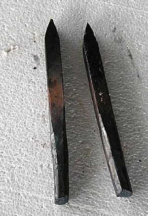
The knife is now complete. A light coat of good oil is all that's needed to finish. The grip area is left "forge finished" as there really in no reason to do much as far as finishing that area. If you desire you can clean off the forge scale and polish the whole thing but you will have more of a rust problem if you do. The scale left on is quite resistant to rust, but it still can rust if it is not kept lightly oiled every now and then.
All in all these are more of a "novelty knife" rather than a serious tool. They will cut quite well as they are but they will need to be reshaped a bit more often than a blade made from a higher C content steel.
They are a neat little knife and a nice "spare time" project for the craftsman or as an exercise to show the basic steps needed to make a knife at a demo or as a assignment for a "student"... -
IForgeIron Blueprints
Copyright 2002 - 2011 IFORGEIRON, All rights reserved
BP0310 Simple Bending Tool
by Jim Carothers
Fellow smith D. C. came over to my shop one day with an idea for a simple bending jig that would produce various radius bends. From the scrap steel in the “learning pile” (thanks Oakwood – good terminology for that stuff) under my workbench, this is what we came up with.
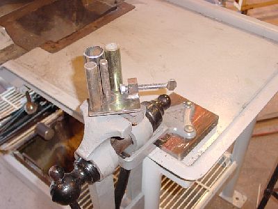
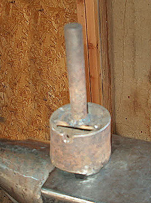
Start with a simple 1/4" plate base with several different sizes of tubing and pipe that will loosely fit over one another. The center post is 3/4” solid round bar, which was pressed into a slightly under size hole in the base plate and then welded in place from the bottom side. The base plate has another piece of flat bar welded on edge to the bottom so that the bender can be held in a vise.
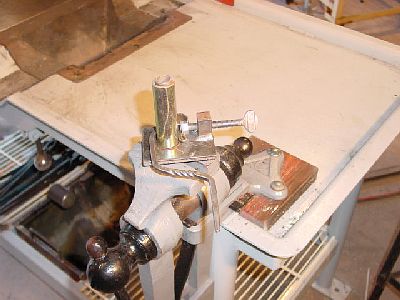
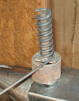
The adjustable pigtail catch is simply a long threaded wing bolt (3/8-NC) with a smooth face flanged nut tack welded on. The heavy block holding the wing bolt was drilled and tapped such that the flanged face nut would just barely clear the top of the base plate. Enough space was left between the flanged nut and the center post such that when it is fully retracted several more pieces of larger tubing could be stacked over one another.
If I were to make another of these benders, I would include a jam nut on the “wing” side of the pigtail catch. That would allow you to lock the catch in position for repeated bends.

This shows the bender with several pieces of tubing / pipe stacked on the center post.
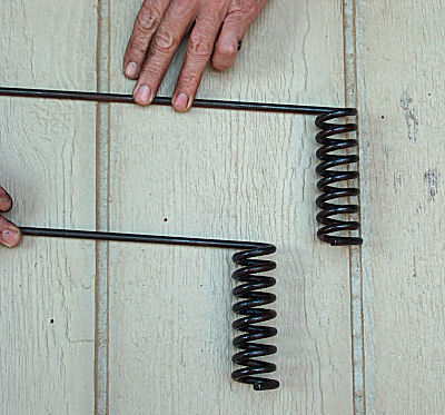
This is the beginnings of a coat hook.
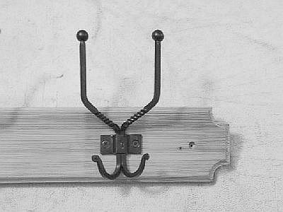
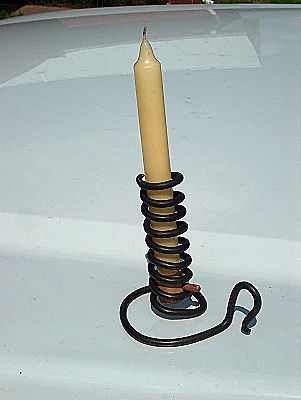
The finished coat hook (1 of 2) on a finished pine board. -
IForgeIron Blueprints
Copyright 2002 - 2011 IFORGEIRON, All rights reserved
BP0311 Chisel Holder
by James Joyce
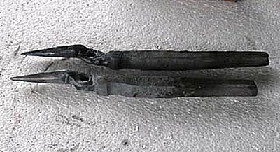
Two pics showing a 4" chisel,
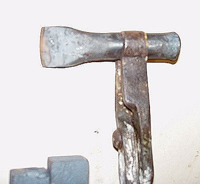
one of a large set of chisels and punches, along with
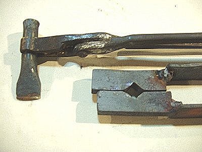
a pair of tongs for gripping the square swaged area along the shaft, and the swage for making the square indent.
Note that the swaged area of the tool (chisel) is well below the top of the tool. This keeps the special tongs from sliding up and off the tool when the tool is hit with a hammr. -
IForgeIron Blueprints
Copyright 2002 - 2011 IFORGEIRON, All rights reserved
BP0313 Curtain Rod
by James Joyce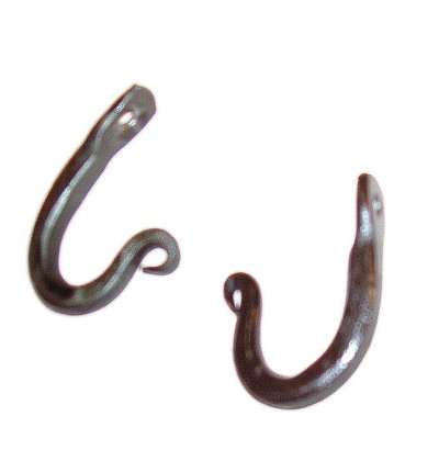
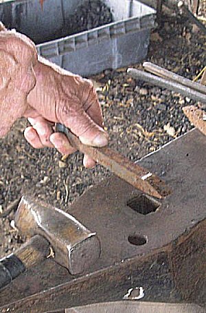
Make small shepherds crook tipped j hooks out of 1/4" sq by 3" long.
Holding hook end with tongs, on nearside of anvil, use half blows to set down last 1/2" of sq end. Drill or punch for 11/64 hole and counter sink with 3/8" drill for installation screws.
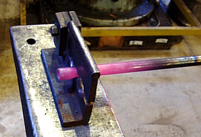
Heat one end of a 5/8" pipe or tube.
Place hot end in a hinged fuller made for 1/2" diameter round swaging. Leave about 1 1/4" of rod sticking past the fuller, and swage down to 1/2" round.
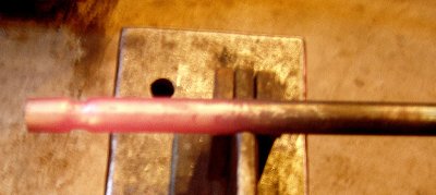
Fullered area should look like this.

Exact location of fullering and length of pipe will depend on window frame width and location you want the hooks to go.
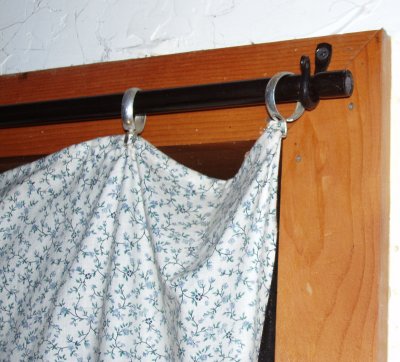
Installed curtain rod and hanging hook ought to look like this.
FYI: Choosing the size of the curtain rod tube:
Remember that the bending strength (deflection / sag) is directly proportional to the diameter of the rod. In the bending strength / deflection formula, the OD is raised to the 4th power. Increasing the OD of the rod just a little will greatly reduce the sag in a given span. Increasing only the wall thickness of the tube (Sch 80 pipe vs Sch 40 pipe for example) mostly increases the weight of the rod and does very little to improve the resistance to sagging.
-
IForgeIron Blueprints
Copyright 2002 - 2011 IFORGEIRON, All rights reserved
BP0314 RR Spike Tongs
by Bill Epps
This is what I am starting with, two ordinary rail road spikes.
I am marking the spikes using the hardy hole as a gage.

From the end make marks at 1 inch, 2 inches, and 2-1/2 inches.
I should have just cut the heads off to begin with. After I flatten the heads, I found it was unnecessary because the rains were to long.
Lining up the mark with the edge of the anvil I set it down forming the first of the three divots.
Setting down the second divot using the front of the anvil first divot on the back of the anvil face second on the front of the anvil face.

What the divots look like ( do this on both prices).


Doing the third divot, This is where the rains start.

Lining the divots up with the front of the anvil face and the off side of the anvil set down (about 1/3 of the thickness) careful not to go too deep at this point

Coming to the front corner to clean up and finish off the joint face

Punch the hole in the center of the joint face.
Hole punched and sized for the rivet used. I used a 5/16 X 1 in rivet on these tongs.
Starting at the second divot, bend down at about a 45 % angle

Coming back to the first divot bring back to parallel.
These are going to be scroll tongs so I taper the jaws to round and to a fine point.
So they look like this

After drawing the reins out I clean up with the angle grinder.

Install rivet and line up the jaws and they are ready to use.
-
IForgeIron Blueprints
Copyright 2002 - 2011 IFORGEIRON, All rights reserved
BP0315 Lay Out of a Cone
by Jr. Strasil aka Irnsrgn
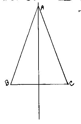
Start by drawing a center line and then draw the cone on the center line full size as shown.
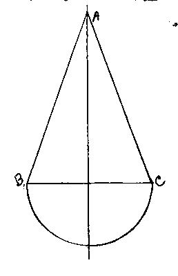
Next using a compass or other means, draw in the hemisphere under the line BC. what this does is give you a half view looking at the bottom of the cone.

Next using a compass, divide the hemisphere into 6 or more equal spaces as shown. On a large cone you will need more divisions, as this is the means you use to get the outside diameter of the bottom of the cone.

Now draw line AB as shown and using a compass or other means using draw an arc from B with A as the center point as shown.

Now using a compass or other means, lay out the divisions as shown and number them as shown to avoid mistakes. Then draw in line AC and you are ready to cut out and form the piece into a cone. If you were accurate in your drawing and transferring of measurements you should have a cone that has a tolerance of the thickness of the material.
If the cone is going to be a large one and needs to be bent on an apron or press brake, draw lines from all the segment marks to point A as reference lines for braking the material. I have made cones for different things up to 15 foot in diameter at the bottom out of 3/16 plate for oil well tank tops using almost this same method.
I hope this helps you understand how to make a cone. -
IForgeIron Blueprints
Copyright 2002 - 2011 IFORGEIRON, All rights reserved
BP0316 Stock Stand aka Third Hand
by Richard ThibeauHere is another variation on a common theme.The parts would be called “scrap” by others, but “parts is parts” and you can use whatever is handy that accomplishes the purpose. Only a couple pieces need to be forged or fabricated. How you shape those depends on what you plan to most use the stand to hold.

These are the parts needed to complete this project.
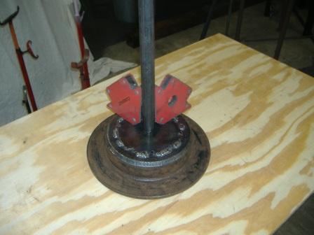
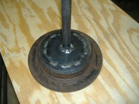
Start with a used brake rotor for the base of the stand. Wire brush the top surface to get it clean enough to take a weld. Weld a piece of steel to cover the center hole and support the shaft. I have used old circular saw blades or any scrap steel big enough to cover the hole will do the job.
Place this larger pipe upright on the brake rotor base, use right angle magnets to get it plumb, weld the pipe to the base.
Support arms can also be welded on to strengthen the stand.

Use two pieces of pipe where one will fit inside the other with as little slop as possible, but still able to slide freely. Length of pipe will be according to the lowest and highest height you want the stand to support work. Diameter of pipe is not critical. Drill a hole in the larger pipe near the top, weld a nut with the bolt in it to the hole.

Weld a piece of steel to the bolt head to act as a lever or wing nut so a wrench is not needed to tighten the bolt to the inside pipe.

Forge a cross piece for the top of the inner pipe, weld it to the pipe. A simple piece of bar, flat or round or square, bent to shape would suffice. Insert inner pipe into the stand, check for ease of adjustment.
Paint the stand in a color or colors that will make it visible anywhere in the shop.It’s surprising how one will blend in with the background and make it difficult to readily spot.
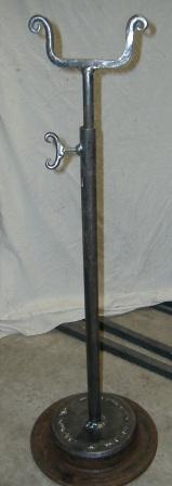
The completed stand before painting.
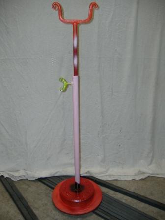
Choose your own color scheme.

The top of the stand painted.
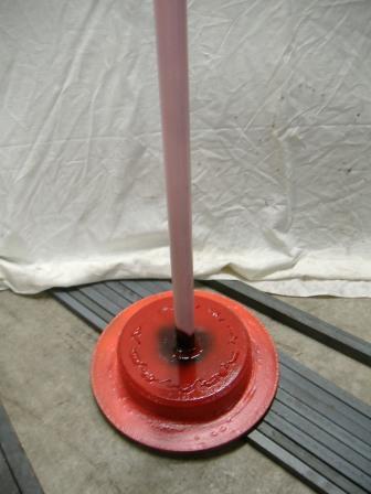
The bottom of the stand painted.
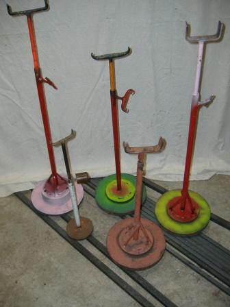
Other stands I have.
One can never have enough tools, jigs, or helpers in a one man shop. I have one of these stands at the gas forge, the coal forge, the vise, the anvil, and two short ones for either side of the horizontal band saw, plus extras. All were made with “scrap” pieces that would eventually have to be hauled off. By recycling them into useful tools, I’ve saved that effort and time and gained more time in the convenience they give. I figure these stands have made me money without having to leave the shop. -
IForgeIron Blueprints
Copyright 2002 - 2011 IFORGEIRON, All rights reserved
BP0318 Tripods
by Glenn Conner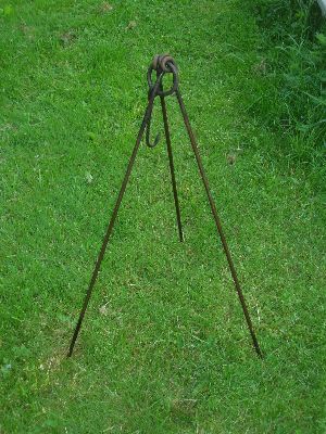

The tripod was shown to me by Bill Epps, and you can not loose the pieces.
Make a closed loop at the end of each of the 3 legs. Make a hook with a loop on one end the same size as the loops on the legs. Now connect the 3 legs and the hook with a ring.

I have built these from 3//8" round to 1" square stock. -
IForgeIron Blueprints
Copyright 2002 - 2011 IFORGEIRON, All rights reserved
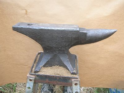
BP0320 Stop the Anvil's Ring
by Glenn Conner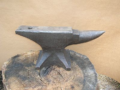
Put the anvil on the traditional wood stump and it allows it to ring. This Peter Wright has been heard at 4 city blocks during the summer. Who knows how far the ring would travel during the cold dense air of fall or winter
There are several ways to reduce or deaden the ring of an anvil. We will cover some of the ways in this Blueprint.
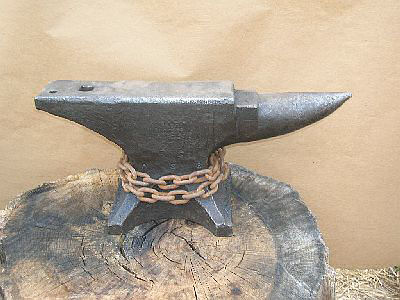
Wrap the waist of the anvil with a couple of wraps of loose chain.
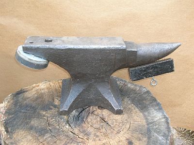
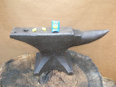
Put a magnet on the anvil.
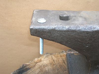
Put a carriage bolt into the prichel hole. Jay Close

Some say putting caulk between the anvil and the anvil stand will deaden the ring.

Others say sand till deaden the ring. Anywhere from an inch to several inches will do.

I think it is just the sweetest sound. From a distance it's like a musical magnet and will never fail to draw me nearer. I say long live the anvil's ring and bad karma to those who want to deaden the song. Ear plugs deaden an anvil's ring...let the rest of us enjoy. Strine

I found to kill the ring is to cut strips of 1 x 1/8 strips drill a hole in each end and place them on the feet then bolt them down. The same goes for a metal stand.. Hotforge101Put a lead sheet under the anvil, roofing lead is ideal. Even a wet rag hanging on the horn will also deaden the ring . Now if you want it to sound like a church bell on the other hand, put cork sheating under it and awaight the croud of egar sight seers. It is good for attracting attention for demos or shows ect Sam Boyd
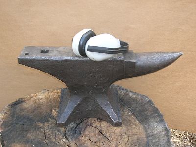
I've heard hang some heavy scrap from the horn with a leather strap.
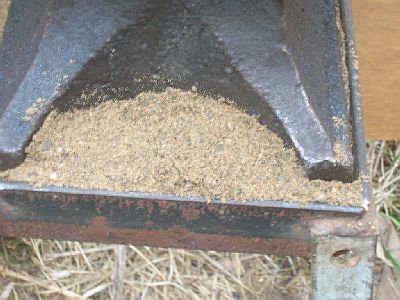
Instead of a stump make a box out of heavy lumber and fill it with sand to within 2" or so of the top and set the anvil on the sand.
Use some light tin, make a form around the top of the stump and pour lead into it to a depth of about a 1/2" to 1" and after it cools set the anvil on top of it.
The sand first two are the ones I've heard of the most, with vering degrees of success. I've only heard of the lead from over at Keenjunk when it was still going. Richard B. Jensen
I have my mousehole anvil mounted on a section of well weathered utility power pole set 20+ inches in the floor of my shop which is about 10" of packed roadmix limestone (fine stuff) over clay. The anvil sets on a 1/8" sheet of lead and is secured with long lag bolts with washers. I really don't mind the anvil ring but out of consideration for those that do mind I tried the lead sheet! It works! It could be the combination of the not so hard stump--the anvil being secure and the lead. The ring is minimal, compared to the portable stand I use it on. Jerry Carroll
I use the ring deadener in the IForgeIron.com blueprint for the European style anvil. For my London pattern anvil, I use a gasket cut from an asphalt shingle that is placed between the anvil and the anvil stand so that the anvil sits on the softer surface of the shingle. It deadens the ring and also levels the anvil up since the bottom of the anvil isn't exactly true and will rock on a steel plate stand without the shingle gasket. Gerald Franklin
Aha this one I can answer, at least a little. For the most part Its been chains wrapped around the base part of the anvil, with a spike wedged in for tension and rubber mats either under the base of the Anvil itself or the wooden post the anvil sits on. I saw both of those types of sound deadener in Holland. Otherwise the vices are just clamped to the base as per normal, ie nails bent over or spikes. The ringing of the anvils isn't a major issue from what I can ascertain, in fact I think some of the lads like it. Plus the Anvils themselves aren't bad as far as ringing goes. I've seen Peddinghaus and a LOT of Kholswa anvils so far, will probably see more now that i'm IN Sweden. lol. As to the ringing signals, if that is not a micky take its something that I'll HAVE to ask the next smith I come across. I've a feeling that its something not many Europeans will know about, but might be wrong. I shall certainly ask, like you say an amusing tale to tell them if nothing else! Ian -
IForgeIron Blueprints
Copyright 2002 - 2011 IFORGEIRON, All rights reserved
BP0321 A Short Lesson on Stress in Iron and Steel
by Irnsrgn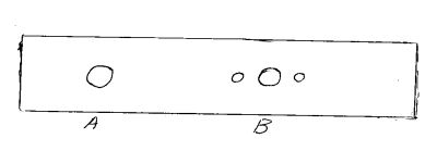
A shows a hole thru a round shaft, B shows 3 holes thru a round shaft, in your opinion which will stress and break first, A or B?

This shows the stress lines drawn in crudely, notice how the stress lines peak over the hole in A, this multiplies the stress by a factor of almost 3, this shaft will break at the arrow. Notice how the stress lines more or less flow over the large hole in B, by adding the two smaller holes the stress factor is lowered by about 50% so the three holes are stronger than the single hole. Any time you drill a hole thru a shaft you add to the stress and thus failure factor.

In the top view, A - shows a keyseat cut in a round shaft with an end mill, B shows a keyseat cut in a round shaft with a milling cutter, this is called a sled run keyseat, notice the round upward sloping.
In the bottom view, the stresses are drawn in. A will increase the stress at the square shoulder by a factor of almost 2.8, B will increase the stress by a factor of .8 , thus B is the stronger of the two.

In this view of shoulders, A is a sharp shoulder and B has a rounded shoulder, A will increase the stress factor at A is almost 4 times that of B.
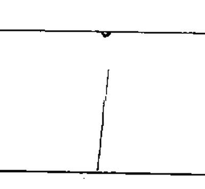
This view shows a nick at the top of the shaft and a scratch 3/4ths of the way around the shaft. If the nick has a rounded bottom it is much stronger than if the nick was a V, like is made with a chisel, this will affect the stress of the shaft.
The scratch is the worst of the two things, as it's just like scratching a piece of glass to break it. Under stress what looks like an insignificant scratch creates a very weak spot that will break easily.
All of these things apply to flat, angle, square and most structural shapes.
I hope this brings a new meaning to stress for you as blacksmiths, creases, dings and cold shuts and folds will greatly affect your work if stress is applied to it.
-
IForgeIron Blueprints
Copyright 2002 - 2011 IFORGEIRON, All rights reserved
BP0322 Making a Nail Header
by Glenn Conner, Illustration by Duck
I want a nail just like Grandpa used to make.

Draw a square taper on a piece of round stock the size you want to use for making the nail.

The same photo but without all the heat. You can see where the stock was placed on the edge of the anvil for half blows with the hammer to form a shoulder where the taper starts to form.
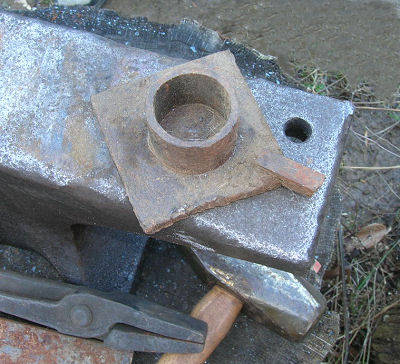
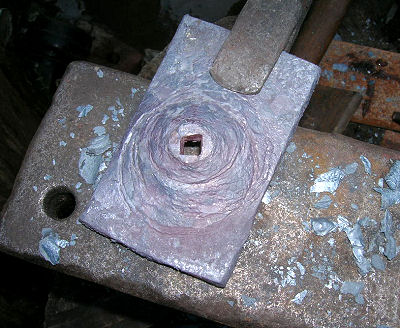
Pick up the nearest jig that has a piece of pipe to aid in forming a dome for the header. This was a jig for forming loops, but it will work for our purposes.

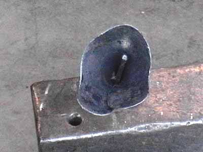
Get a piece of 3/8" x 2" or 1/2" by 2" flat bar and bring it up to temperature.
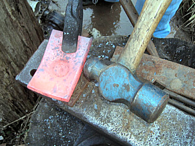
Lay it over the pipe and with a the ball side of a ball pein hammer, create a depression in the metal, by holding the ball pein in place and striking it with another hammer. I have a dead soft hammer for this purpose. Striking two hardened hammer faces together can cause them to chip and throw that chip like shrapnel.

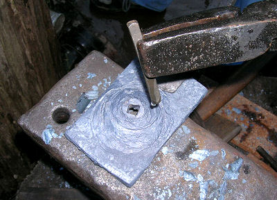
Take another heat and use your square taper as a punch, drift a hole in the dome from the bottom or inside.
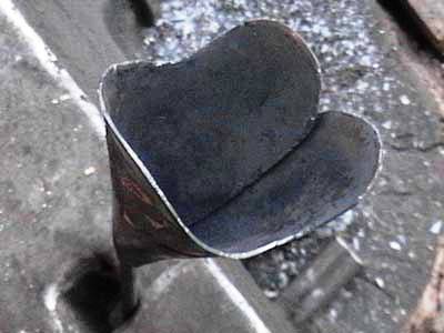
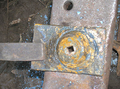
Now with another heat flatten the top of the dome slightly and drive the square taper up to the shoulder you created earlier. This looks a bit rough as the header was pushed into being made quickly. Just a little care in centering the header before each blow will result in a much more pleasant appearance.
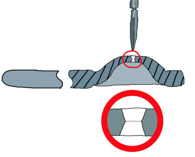
This will create a hourglass of sorts inside the metal. The top part of the hourglass will grab on to the stock as it is driven into the hole so the head can be formed. The bottom of the hourglass will not make contact with the metal so it can be easily removed from the header.
I use a letter punch or touch mark to make an impression in the top of the header at this point.
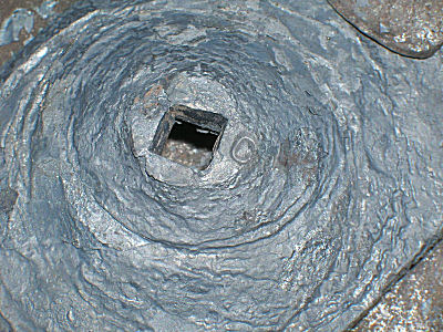
Here you can see the letter at the edge of the header. As the head of the nail is formed, the initial will be pressed into the metal "marking" each nail you make with that header. Yes the finish is rough, but this header was made very quickly, with little care as to alignment when placed back onto the pipe for the next hammer impact. More care in alignment produces a very nice header, or you can clean it up with a grinder..
The finished header. The plan was to weld a handle onto the header so it could be easily held and controlled.
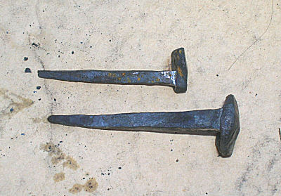
With the help of my son as a striker, this header produced it's first nail in less than an hour from a cold start at the forge.
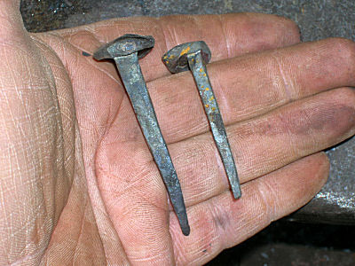
The nail on the left is from 3/8" stock, the nail on the right if from 1/4" round stock.
This is where the Blueprint would normally come to a close, but since we are among friends, I will show a photo of the header after the last nail was made.
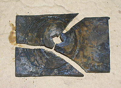
Yes, it shattered !! But I got the one nail made in that header that was required for this Blueprint. Upon reflection, I ask where the metal came from for this header. It was from that stack of drops on the far end of the work table, was the reply. Those were the pieces of leaf spring I had cut for use as plates for hardie tools. And in the haste to get the header made and a nail produced, the header was quenched from a nice low orange color directly into cold water.
I have made headers from mild steel and let them cool naturally with no problems. Have two that I have used for several years now. So, choose your steel wisely and choose your quench, if a quench is even needed. I lost an hours work on this one by the wrong choice of materials. But I did get ONE nail made before it failed. -
IForgeIron Blueprints
Copyright 2002 - 2011 IFORGEIRON, All rights reserved
BP0323 Spirals
by Strine of OzA simple formula for a spiral might look something like R = P and I doubt whether you could get any simpler eh? Apply it like this Draw a point on your layout sheet and call it the centre of the scroll. Draw a line sideways from this point and call this the baseline of the scroll. Now plot points on the sheet where R is the distance in cm from the centre and P is the angle in degrees the ruler makes with the baseline. When you get to 360 degrees ie all the way back to the start the angle just becomes 370 (10) degrees and the distance 370 cm. That gives one scroll with a particular length depending when you get bored with the plotting. Instead of R = P make it R = 1.2 x P, or 0.1254 x P, or 112.365897 x P. Do you get the drift the length could end up as anything depending on your formula. My advice...go with the flow. Draw your scroll any which way and run a piece of string (or any other long skinny thing) around it to get the length.
There a lots and lots of different types of scrolls or spirals. In a mathematical sense if you like and you can alter the shape of the scroll by altering one of the variables in the formula.
-
IForgeIron Blueprints
Copyright 2002 - 2011 IFORGEIRON, All rights reserved
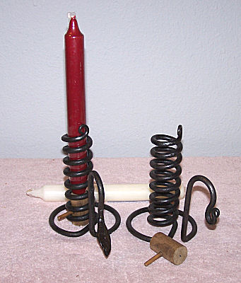
BP0326 Courting Candle
by Gerald Franklin

This is a classic project that is always a good seller and makes a nice gift. They are not hard to make, but the tweaking can be a little time consuming without some aids to help keep things lined up during the forge work. Start with a piece of ¼” rod 4 feet long. This picture shows a piece of 7/8” sucker rod that is used for a mandrel. Notice that I am coiling two pieces of ¼” round at a time. This helps in keeping the coils uniform as they are wound. Thanks to Irnsrgn for turning me on to the double wrap. If you want to have a rat tail curl at the top of your finished candle coil, it is best to taper the ends of the ¼” round stock before you start to coil it.
Make 8 or 9 turns around the sucker rod mandrel and then let the two coils cool before you unscrew them from each other. A little WD-40 or some other light lube helps in getting them apart. If you are careful, and you made uniform coils on the mandrel, they should separate with little distortion.
It’s hard for me to freehand an even base around the anvil horn since the coil prevents the piece from going very far over the horn. I built little jig from scrap 2 7/8” pipe and ¾” sucker rod. Notice the little notch at the near edge of the jig.
Heat the straight part of the ¼” rod, drop the coil over the sucker rod and engage the heated portion in the notch to begin forming the base. Bend the ¼” stock all the way around the pipe and you will have a nicely formed base. You should have enough rod left to form the handle of your choice.

This is a close up of the wooden traveler that holds the candle in and moves it up and down. It is made from pieces of 7/8” and 3/16 dowel, each about 1” long. Coat the assembly with floor wax and thread it into the holder and you’re ready to go. I sell mine with a little card that has the legend of the courting candle printed on it. The story card adds a little sales appeal.
This shows the finished holder with a simple loop handle. You could add a drip pan for an extra touch. The candle in this picture isn't’t trimmed yet. I buy the 8” “Federal” type candles and trim about 2” off the bottom. The “Federal” candles are not’t tapered and fit the 7/8” coil of the holder nicely.
Gentlemen:
Two photos attached of Courting Candle Holders made from the IforgeIron Blue Print done by Saltfork Member Gerald Franklin.
Advice:
Measure the candles (all the candles) before assuming that what you bought will fit in a coil of steel wound around your mandrel. My 7/8" diameter Wal-Mart Federal (straight) Candles are not all the same size. Some were just enough over 7/8" OD that they would not go into the candle holder. Of course, I grabbed one of the "over-size" candles (white) first for a quick check fit in the newly made candle holder; I did not think to check fit all the candles as I should have done. Next I spent a lot of time making a .93" mandrel and "adjusting" candle holders. All is well now though and all the candles fit.
Thanks for taking time to do the BP and your encouragement with my iron work.

Jim Carother
From the IForgeIron Forum:
JWBIRONWORKS
Red face It's stuck Helen?
I needed to make a batch of courting candles for next weekend and I decided to try BP326 by Gerald Franklin. I usually just make one at a time but this looks to be a better way. I cut my stock and wrapped the 2 pieces around my jig, and yes by golly it does wrap better and easier Geralds way.now comes the problem. My jig is a piece of 3/4 pipe welded to a piece of 2" angle so it can easily be clamped in a vice and won't move around. I can't get the wraps off the pipe with out deforming them. I have tried light oil and wd40 and a small punch. Is there something I'm missing here? OH and yes about now I feel stupid. Any suggestions short of removing my head from my rear(I don't have a big enough bar for that) would be appreciated.
Thanks,
JWB
--------------------
Thomas Dean
JW. I'm not sure this will work, but hey, I guess you'll try anything right about now. Grab the bottom of the cork screw and try to unscrew it from there. I think it will open just slightly from there up and slip off. Don't put too much pressure as this will open it too much can it may not spring back where you want it. Not trying to tell ya how to do it mind ya, but maybe you are getting it too hot and it is shrinking onto the rod. Good luck!
Thomas Dean
-----------------------
6013
It is an old blacksmithing trick taken from the Chinese finger trap. Pull and it tightens. Unscrew the coils just a bit and they expand and slip off.
6013
--------------
JWBIRONWORKS
Thanks for the replies guys. I have tried "unscrewing" the spiral, that is how I do the singles that I make. However it distorts the spiral before they comes off. Maybe I will try heating it alittle before I unscrew it. I'm sure the solution is something simple I have overlooked. Maybe I'll have better luck this morning.
The problem may be that I dunked the whole thing in the slack tub so I could get them done "quicker".
Thanks again,
JWB
-------------------
Ten Hammers
My humble opinion. Heat your tooling with a bernzomatic a bit. I have not used this tooling per-se but I use tooling a lot. Stuff will stick, yes. Wrap it, let the color go out and try and unwrap it. I absolutely would not quench. Keep the scale cleaned off ( air hose close by for a quick blast is handy ).
Ten Hammers
---------------------------
irnsrgn
pipe has a rough texture, and it gets hot and expands quick, use a slick smooth shaft for a mandrel, and don't quench it will shrink tight on the mandrel.
Irnsrgn
-------------------------
MOONY
Hit it with a bigger hammer! (just kidding)
Try unwinding it from the top and bottom a little bit, and make sure your pipe mandrel has no burs or marks on it, especially near the top. Linish a bevelled edge at the top to be sure.
MOONY
-------------------------------
JWBIRONWORKS
Smile Problem Solved
I finally got thr first set of the jig and wrapped the second set then before it cooled I put on a pair of gloves and it unscrewed of thr gig just fine. I made the other jig that Gerald had in his bp also. Worked like a charm. I had always freehanded them before.
Irnsrgn, I put the pipe on the belt sander after I removed the first set that was stuck and also cut off about 4" of excess. I beleive that also helped.
Ten hammers, you an Iron were both dead on about not quenching.
Moony. I also beveled the top of the pipe after I had removed the excess length and put it on the belt sander.
Thanks everyone who responded with suggestions, I hope this helps others in the future.
JWB
"I like happy endings"
-
IForgeIron Blueprints
Copyright 2002 - 2011 IFORGEIRON, All rights reserved
BP0327 Belt Grinder
by Gerald Franklin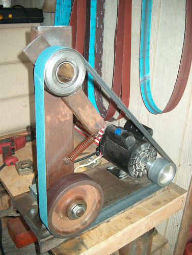
This is my take on a shop built belt grinder (2”X72”) inspired by the one done by Hollis Wooldridge (See IFI Blueprint 215). The mount is a piece of scrap 10” channel and the upright is 2”X4”X ¼” tubing. The 2hp motor is wired for 220v. The contact wheel is an 8” caster and the idler pulley is a pair of salvaged 1” wide bearings scrounged from a local electric motor re-build shop. Total cost was about $110, which includes a new motor and electrical materials.> Does it have a tracking adjustment and is there a picture of that
There is no tracking adjustment per se. Everything is lined up with the drive pulley which I machined with a 1 degree crown in the middle.
> What Kind of Platten is used ?
The platten will be in place for Phase II. It will be a piece of 2" angle bolted to the upright. Phase II also includes a shield around the idler pulley. I need to get that in place before OSHA shuts me down (grin). -
IForgeIron Blueprints
Copyright 2002 - 2011 IFORGEIRON, All rights reserved
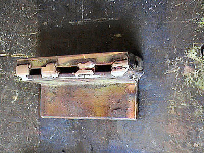
BP0328 Hold Down Clamp
by J.W.Bennett (JWBIRONWORKS)
I have been having trouble positioning and holding on to work while I try to stamp my touch mark into it. I came up with this hold down clamp.

Start with a piece of 2x2x1/4 angle iron approx 5 1/4" long, a piece of 3/4x1/4 flat stock 20" long and a piece of scrap 5 1/2" long to use as the back. I used 2 pieces of 3/4x1/2 flat stock 5 1/2" long because it was on top of the pile.
Cut the 3/4x1/4 into the following lengths 1 - 12" and 4 - 2" making a total of 5 pieces of 3/4x1/4. Using the 12" piece as a spacer lay the other four pieces out evenly across one outside flat of the angle iron. Tack weld The 4 pieces into place(do not weld the 12" piece). If the two outermost pieces should overhang it makes it easier to weld up.
Making sure that the 12" piece will slide in and out of the slots you just made place the Backing plate(S) on top of the 4 pieces you just tacked in place and weld it on. If what you have now resembles this...
The bottom of the jig.

The back of the jig.

Then weld on the sides and top and bottom.
Take the 12" piece of 3/4"x1/4" and 3 1/2" from one end bend it 90 degrees, you should end up with an L shaped piece like this.

On the long side of the L shape come down approx. 1" and drill a 3/8" hole. Slide the L bracket into one of the slots on the angle, Place it in the vise and your ready to try it out. Use a small C clamp to apply the pressure. The flat of the angle iron makes a good backer to stamp or chisel.

Clamping a rose stem.

Once you are done working with it, use the hole in the L bracket to hang it on the wall.

When finished just hang it on the wall. -
IForgeIron Blueprints
Copyright 2002 - 2011 IFORGEIRON, All rights reserved
BP0329 Shelf Brackets
by IrnsrgnThese are the shelf brackets I put in the wood working trailer to hold stock.
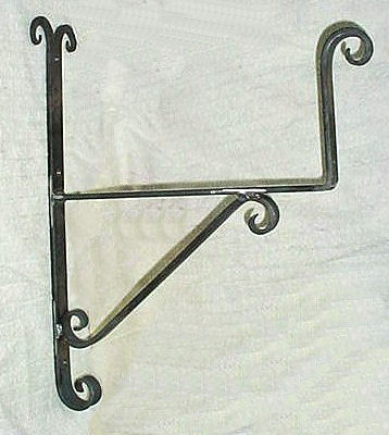
The wood simply rests on the shelf. The weight of the shelf is then supported by triangulation back against the wall through the scroll piece.
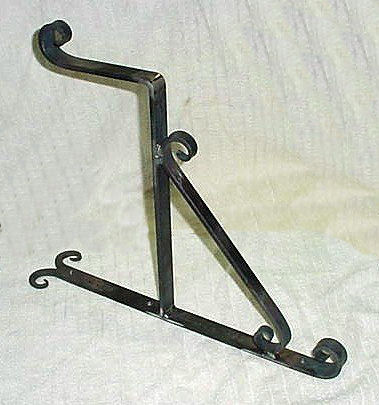
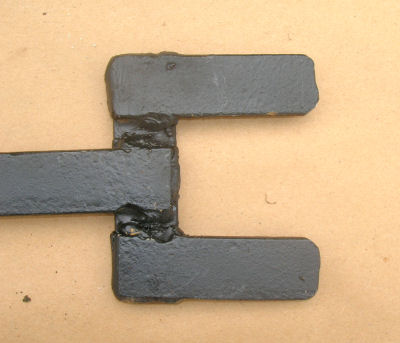
You can see how it is welded together, making a strong connection. -
IForgeIron Blueprints
Copyright 2002 - 2011 IFORGEIRON, All rights reserved
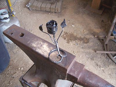
BP0330 Car Parts
by Glenn Conner

This is a wrench for removing the radiator fan on an automobile. You insert a 1/2" drive ratchet handle into the square hole and then the wrench onto the nut between the fan and the engine block. Usually jamming the fan and turning the wrench is enough to break loose the nut. Then just spin the fan off the shaft while holding the wrench steady.
In talking with the mechanic, it was a cumbersome system. I ask if a rigid handle would do as well and his eye sparkled. He said "YES !! Can you do that?"

Well being a blacksmith I just welded a 22" handle onto his wrench.
He met me at the car the next time I visited. Had the whole fan assembly from a car and wanted to know if I could make a new wrench to fit. I ask if he broke the old one. No, this was a different car with a different size nut to hold the fan. Doesn't have to be pretty, just so it works.
I found a piece of 1/4" x 1" flat bar and cut it to 3" in length. Welded them together in a "U" shape.

Welded the remainder in place as a handle.

Fits well enough to get the job done.
BP201 Easy to make tongs
in BP 200 Series
Posted
BP201 Easy to make tongs
By Whitesmith Copyright 2002
IForgeIron Blueprints Copyright 2002 - 2017 IFORGEIRON, All rights reserved.
BP001 Easy to make tongs
by Whitesmith
Whitesmith is a 10 year old that provided IForgeIron with the following easy to make tongs.
Start with 2 pieces of 1/4" x 3/4" x 20" long flat bar. Drill, or heat and drift, a 1/4" hole, 3 inches from one end, and in the center of the bar. Insert a piece of 1/4" round rod into the hole. Put a vise grip on the handle end to hold the two pieces together and heat the working end of the tongs to orange in the forge.
Place the tong end in a vise. Put a crescent wrench just under the piece of 1/4" round rod and adjust the vise so there is about 1 inch of space between the bottom of the wrench and the top of the vise.
Turn the wrench 90 degrees or 1/4 turn. You are turning BOTH pieces of bar stock at the same time, and in the same direction.
This shows how it looks from the top and the side.
Remove the rod. Heat the tong end in the forge and then shape it for what you want it to do. This set of tongs was being built to hold 1/4" round stock. The tongs can be taken apart and worked easily in the forge. When you want to see how you did, put them back together with the rod.
When you have the tongs shaped the way you want, heat the end of the 1/4" round rod and put it in the hole in the tongs. Clamp it in the vise and pein the end of the rod to form a rivet head
Once you have made a rivet head from the end of the rod, cut the other end of the rod off, leaving enough rod to make a rivet head on that side too. Put the whole thing in the fire and get just the end of the rivet hot. You can make the rivet head with the rod cold, but a little bit of heat makes it work a lot better. Put it on the anvil and pein the end over to form a rivet head. Be careful not to get it too tight. You can always make it tighter later, just pein it again, but you can not make it loosen up by hitting it with the hammer. Note: For the rivet, leave about 1-1/2 times the diameter of the rod to make the rivet head
These tongs have just about the right space at the end of the handle to work for me. You can heat and bend the handles to adjust the space to fit your hands.
These are not heavy tongs, and will not do the work of heavy tongs, but they will do a lot of work and are quick and easy to make.
Edited by Glenn