June 8, 201511 yr with the assistance of some very helpful and generous friends i purchased a columbian post vise at the alameda flea market yesterday. it took three of us to carry it the half-mile to the car (ok, michael, i should have gone back with a rolling cart, sorry); reading anvilfire on post vises i see it probably weighs about 140#-150#, which i certainly believe. moving it from the car to my forge took five minutes, and it's only 50 feet to carry i didn't get any shots of it yesterday; i will post pictures tonight after i take them.it has jaws that are 7" in width, and while they are slightly out of alignment one side to the other, they are parallel and meet vertically in the same plane. i think the only thing missing on it is the nut to secure the pivot bolt that captures the moving jaw in the bracket. i wonder if that's what's allowing the jaw to move from side to side when it's closing? i will measure and buy a nut to replace it; on columbians were they square nuts or hex?i'm going to clean it up, then mount it on a stand. for cleanup i was going to hit it all over with a wire wheel (to get rid of the multi-layers of paint, and rust) then rub it over with a turps/BLO/beeswax mix i use for many things. i was going to unscrew the screwbox, clean off all the old grease with solvent, and re-grease. any recommendations for weight of grease, or type? white lithium? or heavy machinist's grease? i read somewhere that motor oil works, too. any thoughts will be appreciated.i am excited as hell to have this, because refurbing the 4" vise i got cheap has been a longish process (i am a beginning blacksmith, and am learning by doing, but slowly ). now i can get this one cleaned up, mount it on its stand, and use it...even while i keep working on the other vise to get it usable.thanks michael, kirk, and paul for the assist.
June 8, 201511 yr That is a KEEPER! But don't get rid of your smaller one. I like having a large vise and a small vise mounted on the same workbench to be able to use the one best suited for the task.I assume that you just popped the bolt out and carried the moving jaw separate from the leg jaw?I've replaced pivot bolts and nuts; never cared as to if they were sq or not. If the head of the bolt was sq then the nut probably was too. Neatest mod I've seen was a fellow brazed a cover on the back end of the screwbox and mounted a zerk in it to lube the vise screw from the back pushing out trash every time he lubed it. Don't forget to lube the cheeks of the pivot set up too.
June 8, 201511 yr Here's the beast, took 3 of us to carry it out, with a 4th guy running blocker for all the crowds looking at their cell phones. Once we got moving there was some INERTIA in our forward progress.a few years ago I got some help carrying a 60lb vise out of that flea market, that was a feather compared to this thing.That's an oversized, Costco style shopping cart by the way.
June 8, 201511 yr Author good shot, michael. thomas, i didn't even think to knock off the moving leg. DOH! we finally got it to the front and michael snagged the cart, and we took it to the tailgate of kirk's truck for pictures (per our usual alameda finish).i will check with the bolt head. i might replace the bolt with a similar size grade 8, not that it will make any difference, i guess.thanks. and again, and again, michael
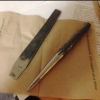
June 9, 201511 yr Author some more pictures. the vise, next to the 4"-jaw vise I am still refurbing, the face of the moveable jaw after wire brushing (interesting dot pattern!), and the pivot bolt. I think I will replace the bolt with a new one!
June 9, 201511 yr The stripped bolt doesn't need to be replaced. Depending on fit, just cross drill for a hair pin, cotter pin or bent nail. That is one beautiful Brute!
June 9, 201511 yr Author cleaned the threads, they look pretty good, as does the thrust bearing. will wire brush it tonight. Edited June 9, 201511 yr by madwing testing
June 9, 201511 yr Nice score. I picked up a 6" a while back, its my biggest so far and is right at 100 lbs, that one is a beast. I want one : ) .
June 10, 201511 yr notice that it stands lower than your other one to facilitate heavier work on it---like with a hand sledge!
June 10, 201511 yr Author Eddie, I feel very lucky. But 6" is no tiny vise!Tom, I noticed but didn't make that connection. Good call!Oh, and Fastenal has an exact replacement square bolt, and nut, for about $5. I get those on Friday. Edited June 10, 201511 yr by madwing
June 10, 201511 yr Author here are a couple of similar shots of the incipient base. it is the base, table, and column of a mostly-gone Rockwell 15" droll press. that is a 6# sledge in the one picture...i am going to cut off the column and weld a 1/2" thick top plate at the right height for the mounting plate, and have the original table turned 90deg to the base as a tool table. I will probably weld support wings on 4 sides of the column to the underside of the top plate.an advantage of this is I can mount tilt casters on the back of the base, allowing for tilt and roll!
June 10, 201511 yr Author I ran into a bit of a snag tonight. I had assumed the screwbox was slip fit, if indexed, and that it would slide out when I pulled the screw.no dice. it is loose in the socket of the leg, and is indexed, but I can't find the right way to turn it to get it out. is there a trick to this? could clumps of old grease and scale be jamming it up?i sprayed a whole lot of degreaser in and around the screwbox...but shouldn't it just slide out?
June 14, 201511 yr Author after getting the screwbox unstuck, and the vise all cleaned and waxed, I prepared the drill press base and mounted it temporarily. i have to weld the plate on top of the vertical tube, and gusset it, and mount it permanently. Edited June 14, 201511 yr by madwing
June 14, 201511 yr I like the plan. Will the base be solid enough to do heavy bending or hammering against? Are you going to leave the drill table free to move? I love having a tool table on my portable vise stand but mounting it so it's out of the way for bending is important. Being able to loosen the clamp and swing it out of the way or where it can act as a helper would be SWEET.I'd be inclined to mount it so the leg pin is about centered in the base or as close as a good solid mount for the mounting plate allows. I know it's just clamped there for the pic but I had to say. . .Thanks for the process pics.Frosty The Lucky.
June 14, 201511 yr Author cheers, frosty.i am thinking the foot will be about 3" in front of the post when it is all said and done, allowing good clearance to pivot the table. I might center the mounting plate over the post, which would push it out another inch, too.in either case I am planning on running a piece of 1/2" strap bolted between the t-slots in the base. I will drill a seat for the post, and put a layer of sorbothane between the steel and the base, to absorb shock. hopefully I can wail on it, then unfortunately the the jaws want to close offset a half inch. this is down to the pivot box bolt and the base of the spring, I think. gonna tweak that once I get it all mounted properly, though.
June 14, 201511 yr In am also having some doubts on the integrity of the cast iron base. You might want to consider a plate under the base so that when it is used the force goes straight to the ground. May even drill a hole so the foot goes through the base, and onto a steel chunk.
June 15, 201511 yr Good catch Guns, I knew there was something else caught my eye but I got involved in expressing myself. Hammering on a cast iron base isn't a good thing and a layer of rubber, etc. won't do the trick. Maybe drilling so the leg will pass completely through and socket into a steel plate laid on the floor and bolted to the cast stand.And don't worry too much about the jaws lining up exactly, they don't. A little tweaking is the norm I can't remember many with jaws that lined up height wise and they're supposed to cock a little sideways, it's how they grip odd shapes.Frosty The Lucky. Edited June 15, 201511 yr by Frosty
June 15, 201511 yr Author i've had my wonders about the cast iron base. i have also wondered about putting a hole in it, and putting a rod vertically underneath onto a piece of steel cross-bolted to the base. i'd just think that would transfer the stress from the surface of the thing to the points where the strap was bolted in (leg/vertical rod/cross-bolted steel is how it'd transfer), and rather than being a pounding it would involve shear at the boltholes, on the bolts. i'm thinking a 1/4" thick plate for it to rest on now covering the entire flat part of the base, with sorbothane between that and the base, held on by 4 t-slot screws with the leg coming down somewhere in the the middle. the plate would flex, or take the stress, and there wouldn't be any drill holes in the base to weaken it.here's a rotated picture. Edited June 15, 201511 yr by madwing missed a parenthesis
June 15, 201511 yr The idea of having a large vise is to be able to use it for heaving hammering trying to put a shock absorber anywhere in the system is like saying you want to modify the shocks on your car so they are rigid---no way to do it and still get them to work as they are intended to!I'd find as thick a steel plate as will fit under the base; hopefully around 1" or more and drill a large enough hole in the base that the end of the leg will drop down and rest on the hidden plate. A bit fancier would be to have the hidden plate and then weld in a solid cylinder with a hole for the end of the vise leg that would go up through the large hole drilled in the base with a close fit. Making it so you do not need to modify the height it mounts at.
June 21, 201511 yr WOW! That is a nice vise restoration and the most awesome vise stand i have ever seen! Good idea and i like the table as a rest.Thanks for sharing the last picture!Greetings,Hannes
Join the conversation
You can post now and register later. If you have an account, sign in now to post with your account.