Hefty
-
Posts
288 -
Joined
-
Last visited
Content Type
Profiles
Forums
Articles
Gallery
Downloads
Events
Everything posted by Hefty
-
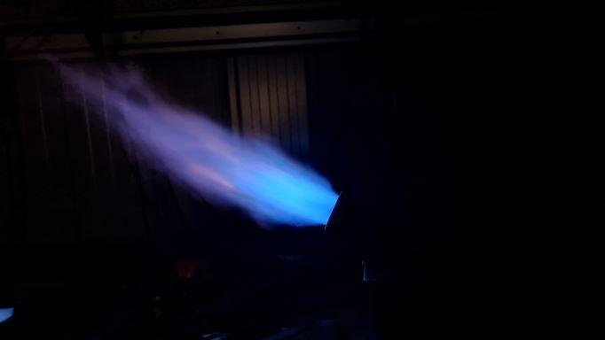
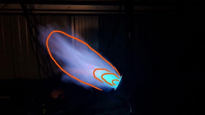
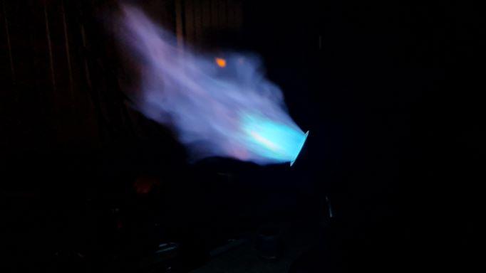
Thanks Mikey. That's the other thing I'm still struggling to interpret, the parts of the flame. Can I ask you if I'm interpreting these pictures correctly? They were from beginning to tune my T burners. ( I've already posted them in the T burner thread for that purpose, but I post them here to learn how to read them myself) This is the same burner, low, medium and then high pressure. My interpretation is that the first one is still quite reducing, indicated by the green tint but also from the whitish secondary flame at the tip of the primary flame. The second one is less reducing with no whitish secondary flame but still a slight green tint. The third one is more neutral as more air is being entrained at the higher pressure. Am I reading this correctly/looking at the correct parts of the flame?

-
Hmmm, that sounds logical but also makes me wonder even about my flame reading ability
-
I've been tinkering with the T burners and 3D printed vortex burners I've recently made and I'm getting more confused about reading and tuning flames, instead of less so! I had my two 3/4" T burners with .035" mig tips running what I thought was slightly reducing (slight aqua/green tinge to the primary flame? Is this right for reducing/rich?) but more neutral as I increased the pressure (a more pure blue?) due to more induction of air. Follows my understanding of the induction curve they should follow. But last night I did a comparison of that with my 3D printed 1/2" AFB version 30 copy with a .023 tip and I couldn't get that more pure blue colour regardless of where I put the tip. Does this suggest I should got to a slightly smaller tip so there is less fuel for the amount of air able to be induced? On a similar but side note: I've been struggling with how to read flames and the thought occurred to me last night: Would kitchen stove burner flames make a good benchmark for comparison? Are they designed to be reducing so as not to damage steel pots and pans? Because they run at less pressure, it's easy to see the aqua/greenish blue primary flame and the blue secondary with flecks of yellow/orange. Sorry for all the scattered questions in my long and rambling post! Cheers, Jono.
-
3D printed plastic burner experiments (photo heavy)
Hefty replied to Another FrankenBurner's topic in Gas Forges
I'm definitely serious about getting the other parts of the forge right, I just don't have the materials yet. I have an old 9kg gas bottle and two old disposable helium tanks (about the same size as the gas bottle but thinner steel) to choose from for the shell. There's a very small market for refractory materials at the hobby level here but the one supplier in Australia (that I know of) who specifically deals with "hobbyists" and "artisans" has a kit with ceramic wool, rigidizer, satanite and a fire brick for a door, so I've just got to save my pennies. I started with the burners because the parts are cheaper and (slightly) more available (especially the 3d printed part for me). Mikey, with baffle walls do you mean, for example, setting a wall perpendicular up against one interior wall of the forge and a door parallel to that baffle but up against the opposite side of the forge kinda like this: Where the blue are the baffles and the exhaust path indicated by black arrows. Cheers, Jono. -
3D printed plastic burner experiments (photo heavy)
Hefty replied to Another FrankenBurner's topic in Gas Forges
The alignment is good, just the copper tubing is "pre-loved" refrigeration tube so it's not perfectly straight before it enters the plastic. The end and the MIG tip are pretty well aligned inside the plastic. Hehe, no, I didn't try the hand bevelling. When I read Mikey's response I had a bit of a head slap moment: I have access to a 3d printer and I'd been reading this thread for a while so why wouldn't I just print a vortex inducing head? I'm planning to use this one as a torch for smaller/shorter heats so hopefully the roar won't get to me too much, but I do also plan to make a narb for the 3/4 T burner I made for a forge. You guys and your burner designs have all just reignited my joy of curiosity and tinkering! Cheers, Jono. -
3D printed plastic burner experiments (photo heavy)
Hefty replied to Another FrankenBurner's topic in Gas Forges
So, I hope you don't mind AFB, but with some of your dimensions, and some guesstimations, I've reverse engineered a version of your v30 in 1/2" for myself. It works like a charm!! Thank you for all your hard work! I don't have a nozzle yet and I haven't had time to really play around and tune it but I lit it for the first time tonight and got a stable flame straight off the mix tube at low pressure. It's not hugely evident in these photos but I can see the vortex in the flame even at low pressure like some of your photos earlier in the thread. I can't wait to get an appropriately sized nozzle attached to it and really put it through its paces! Cheers, Jono.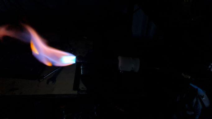
-
Ok, so after a bit more reading I turned the threads out of my pipe coupler nozzles just enough to create an even step instead of a step and then another restriction and both burners now light reliably. This has put me a few steps back in my tuning but I'm happier with less hassle lighting them and I know I shouldn't get too hung up on tuning them properly until they're mounted on a forge. So, I guess my previous questions are now void
-
Hehe, yeah, I learned they aren't real thick when I broke through the edge of that tee earlier Two questions then: 1. Is my alignment what is making my burners touchy to light? I've seen videos of people lighting them with a single "touch" from a burner torch but I have to hold the torch at the tip and really fiddle with the pressure to prevent huffing out or burning back until it heats up a little. 2. Will these alignment and lighting issues still be as evident in a NARB if I use your 90* turn mixer/plenum style, or will this render that a non-issue? Cheers, Jono.
-
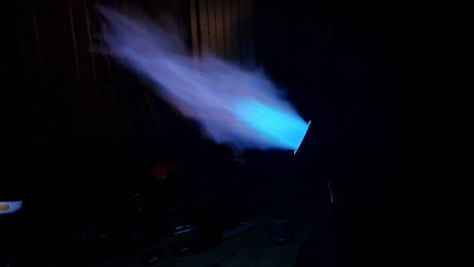
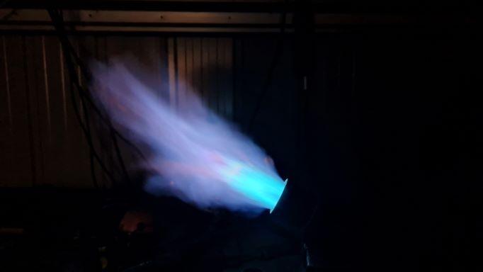
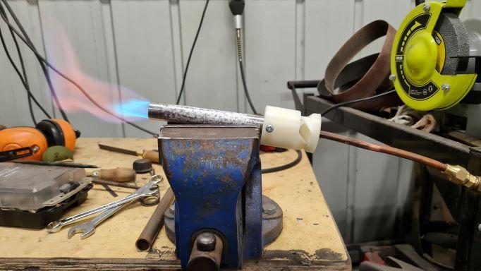
Ok, I learned a lot yesterday afternoon/last night! I'm still having trouble getting the burner lit initially. It is a really fine balance between huffing and lifting off the nozzle and I think it is only once my little butane can torch has heated the nozzle that it stay lit more reliably. The more I read about this the more I think that my jet alignment is still a little off. Even in the lathe, I think I'm having similar issues to Trees with drill bit deflection before tapping. But, once I got it lit I took still shots of after my first tuning trim. I filed off about 1/32", or, just under a mm. At low pressure: At medium pressure: At what I used to think was high pressure: And, now I know what you people mean by jet roar!: Based on these photos, can I ask: Is the next photo correct for identifying the different sections of the flame that I should be looking at? If I am correct then I think I am still reducing at the lower pressure and more neutral at the "jet roar" stage. This has also taught me two more things: 1. I really need a regulator so I can replicate conditions consistently 2. I think I'm going to need to look into putting this into a NARB or my neighbour might kill me! Cheers, Jono.


-
Yeah, I had to google it: Price I think Mikey's fingers were all one key to the left
-
I also have a question about inducing a vortex, prompted partly by your book and partly by AFB's 3d printed burners. Apologies if it has been answered elsewhere, I'm trying to get through all of "burners 101", all of "forges 101", all of "Frosty T burner Instructions", all of "3d printed plastic burner experiments" and your book in PDF form! In your instructions in your book you talk about putting bevels on the interior of the leading edge and exterior of the trailing edges (lip of the reducer)of the air intakes to reduce drag while still guiding the air. Did you ever try complimentary bevels on the long edges of the slots as well, to further induce vortex? As in, say, the exterior of the left long edge of each slot and the interior of the right long edge of each slot? My thinking is that this might be a "poor man's version" of the helical aerofoils in AFB's burners? Cheers, Jono.
-
Mikey, I have more ready access to 3d printer extruders than mig tips and I can get them in 0.2, 0.3, 0.4, 0.6, 0.8 and 1mm but they aren't as long (only about 1/2" long). Could I use a 0.6mm or 0.8mm in a 1/2" mikey burner for a torch or would their shortness render them unable to be tuned? Cheers, Jono.
-
Yeah, I had to use the conical outer section of a tail stock drill chuck to centre them because I didn't have a big enough live centre, and I only figured out I could do that after I messed up the first one. I seem to keep finding helpful info just after it would be helpful. I had read some of your info on intake to mix tube diameter ratios for inducing more air but missed the fact that I could run 3/4" equal tees unmodified with a smaller mig tip. Oh well, I'll know for next time. Anyways, I managed a reasonably stable flame on the tee I didn't have to cut down and I got a video. This is untuned with a full length mig tip. You can see it sputtering slightly at lower pressure at the start, then it settles into a stable flame when I bring the pressure up a bit but then I turned the pressure up too high at the end and it blew out off the nozzle. I'm very new to reading burner flames but I'm presuming from the second layer of blue and orange flame (and the fact that I haven't trimmed the mig tip yet) means that this is a fuel rich flame, yes? First Tee Burner Flame - Untuned Also, how do others light their burners? I don't mean that to sound like a dumb question but I'm using a little butane can torch to light the FAM as it exits the mix tube and I really have to play with the regulator carefully to get it to light without blowing the flame off the end of the mix tube. Is this something that will be less of a problem when it's mounted in, and tuned for, a forge? Cheers, Jono.
-
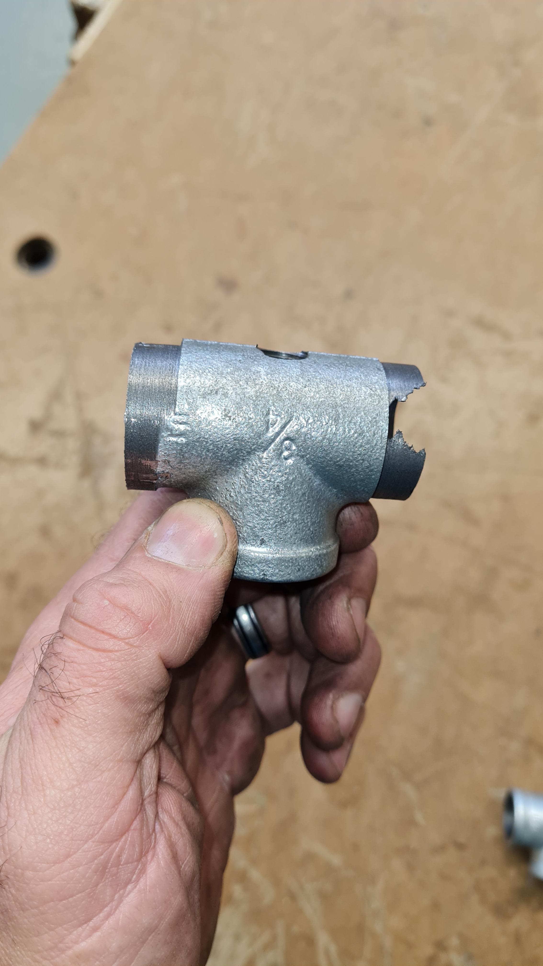
Ok, so once I found time to phone around, I confirmed that even most plumbing supply places around here don't carry much in the way of iron pipe fittings and none of the ones I contacted had reducer tees. I got some 3/4" equal tees and turned out the threads on the air intakes. One turned out ok, the other one was bored so off centre from its casting that I broke through the section where I had to true up the outside to the same centre as the nipple I had it on so I could hold the second side in the lathe chuck!! I've had to cut off the broken section and the other side to match. Will this still work? It still has a little bit of iron with the right sized holes in the perpendicular alignment before the her and mix tube, but not much It funny/sad: I consider myself reasonably handy but, Frosty, you designed this to be fairly easy to construct and I'm still messing things up! Actually, IF the shorter intakes on the tee end up working, in future I might just cut the thread section off without any further turning. They actually get bigger inside after the threads!

-
Yeah we do have them but they are less common. Well in my my area we are in a sub-tropical climate so it's more air con than heating. And yeah, we have plumbing supply stores but they can be a bit "hit and miss". Some sell to the general public but some only deal with tradies who have accounts with them. I haven't found any helpful ones close by yet. I guess I'll need to do a bit of a phone around and see what I can find. Otherwise I can order them online but the shipping is twice the price of the item itself and I'm pretty cheap Our main big box hardware store "Bunnings Warehouse" has stores in most suburbs. I've got one about 3 minutes from home and another bigger one 10 minutes past that. They have equal tees and reducing fittings but not reducing tees!
-
Frosty, I'm reading through the burners 101 thread and I saw that early on you tried turning the threads out of the tees but the only practical advantage was the enlarged air intakes. Because I'm impatient and because our big box stores have equal tees but not reducing tees, I'm considering doing this to save shipping time and money on a reducing tee. But, before rush into it, I wanted to check if the centering of the two intakes is mission critical, knowing the issues I've already had with castings not being true. I could thread one side onto a nipple to centre it but I would literally be turning the threads off that would hold the other side in order to do the same. Another thought has also come to me but it may be too dodgy: Could I JB weld my off-centre holes shut and then re-drill and re-tap? It would end up with mostly metal in the new holes with a section of JB weld down one side. Cheers, Jono.
-
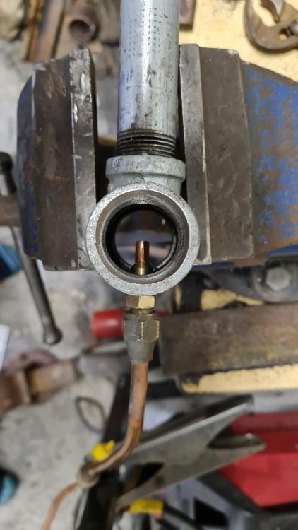
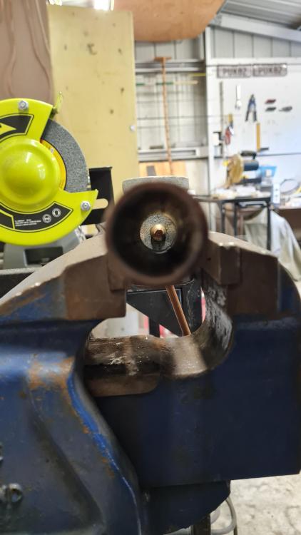
As Holmes said to Watson at dinner time: "Rats! Foiled again!" Frosty, you were right about alignment but I think the pictures were a bit misleading. It's not so much that everything is on an angle to the tube (Well, maybe that too with the original MIG tip) but actually that the hole for the brass fitting about 1/8" or so to one side of the centre of the mix tube! ON BOTH TEES!! Foolish me, way back when I drilled the Tees in the lathe, didn't think about the fact that as a cast part, the centres of the machined holes don't necessarily correspond to the centre of the outside of the casting Oh well, I'll have to order some more and get really impatient waiting for them to ship. Still, thanks again everyone for the replies. I've still learned heaps that will get me started quickly when they arrive! Cheers, Jono.
-
That's the best little tidbit I've come across in a while JHCC!
-
Sorry, yes, I meant gas rated tape. I know not to use normal teflon tape with gas but that is probably what I read/mis-read elsewhere about not using thread tape with burners. I understand what you mean about scraps blocking things up and I'll follow AFB's instruction with the thread tape not past the last thread. For the amount I need, the thread paste is almost 10 x the price of the tape. I'm getting close. I can feel it! Cheers, Jono.
-
Thanks for the replies! AnotherFrankenBurner, I'm glad to hear that people do use thread tape here because that will be my easiest fix. I'll have to try and find where I was reading about not using it and see if I'm missing something in context. Frosty, I am using a 1/4 x 1/4 flare coupling I understand your instructions on the drill press. I think the issue was just the mig tip itself but I remember when I drilled and tapped the Tee I wasn't sure if the shape of the fitting was true enough to rely on for centering. I'll keep an eye on alignment once I get new mig tips thread sealed in both burners. Cheers, Jono.
-
Ok, so I tried with a new MIG tip and I've almost got it to the point where it will stay lit. It's now huffing instead of sputtering at slightly higher pressure but I noticed, before quickly shutting off the ball valve, that when it burns back into the tube to the MIG tip at low pressures, gas is leaking from around the MIG tip thread. I've been reading that gas thread tape is a no-no in these burners but I presume gas leaking out near the air intakes (apart from being unsafe) is going to affect its ability to induce air. So, any advice on how can I stop the leaks?
-
Hmm, I see what you mean. I just hope it is only the mig tip and not the threading of the brass fitting that has made it crooked in this one. I even used the metal lathe at work in the hope of keeping it central! I'll try a new mig tip first. Our big box stores don't have as much in the way of steel pipe fittings so I may have to order another T online if that's the problem.
-
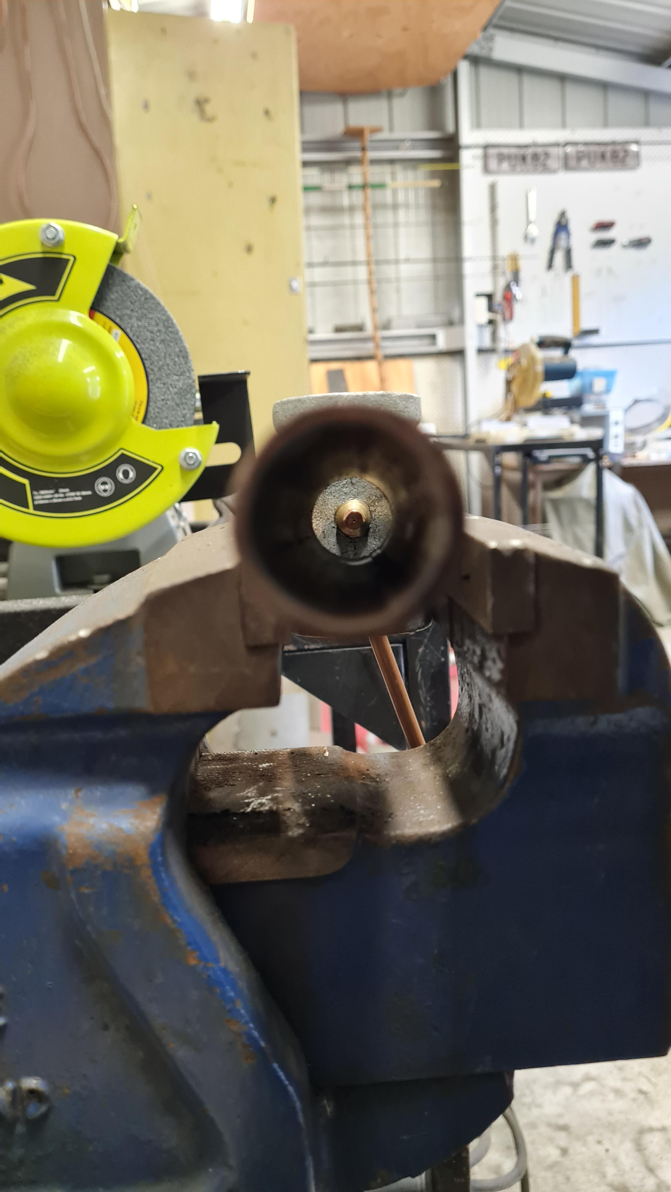
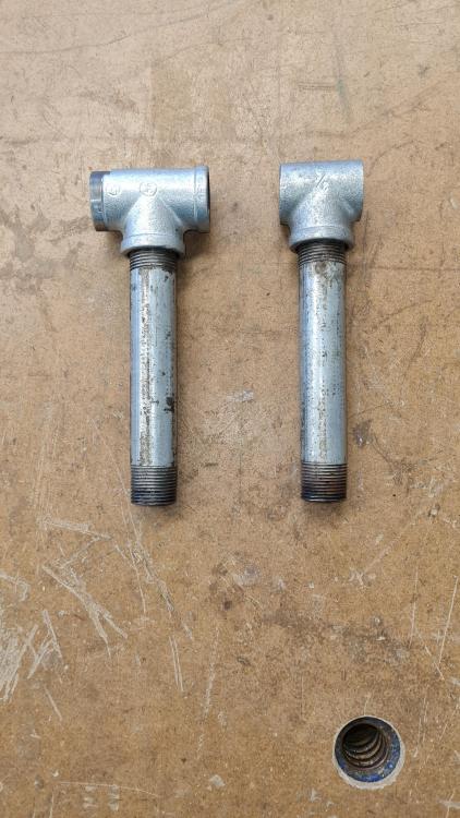
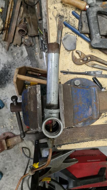
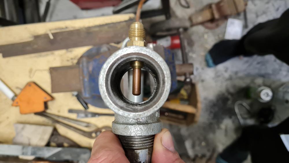
Ok, here's some photos of what I've put together: The overall assembly The central alignment Where I've trimmed to And the other burner with and untrimmed MIG tip. And yes, I will remove the gal with vinegar before any significant burning. Cheers, Jono. Edit: I've just re-read the PDF instructions. I originally focused on the word "optional" in the heading "Burner flare of your choice (if needed/optional)" instead of "If needed/optional" Could this be as simple as adding a thread protector or pipe coupling flare?
-
TLDR: What would be the most likely cause or causes of sputtering/burning in the mix tube or flame blowing straight out in a 3/4" T burner? ______________ Hi all, I generally don't get to forge more than once a week, let alone work on building my gas forge, which I've been doing slowly, come'n'go style, for about a year now. I've got 2 x 3/4" T burners built with all pieces as per the sizes from the PDF instructions. I've been trying to tune one for a while now (but again, only for a little while at a time with long periods of time in between) and I cannot get it to light without it either blowing straight off the end of of the tube at higher pressures or sputtering and burning in the mix tube at low pressures (sorry no gauge yet). I've been trying to trim a little at a time and check for burrs in the orifice but I'm having no luck. I will try to get some photos to add this afternoon but is there any, more general advice that I'm overlooking that might cause this? Thanks, Jono.
-
What did you do in the shop today?
Hefty replied to Mark Ling's topic in Blacksmithing, General Discussion
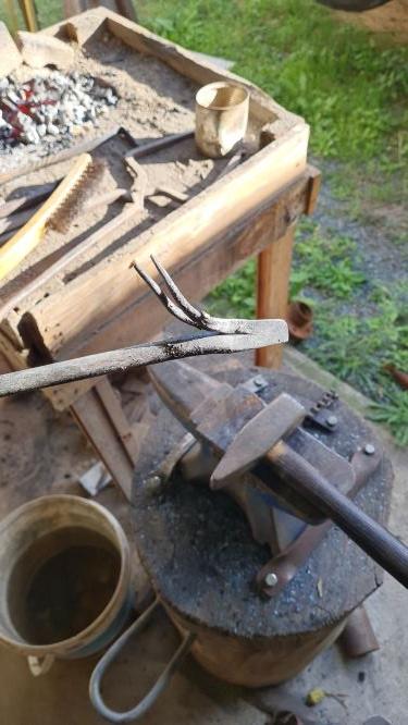
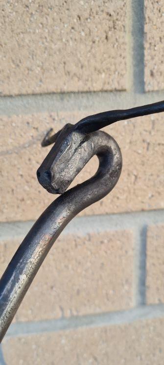
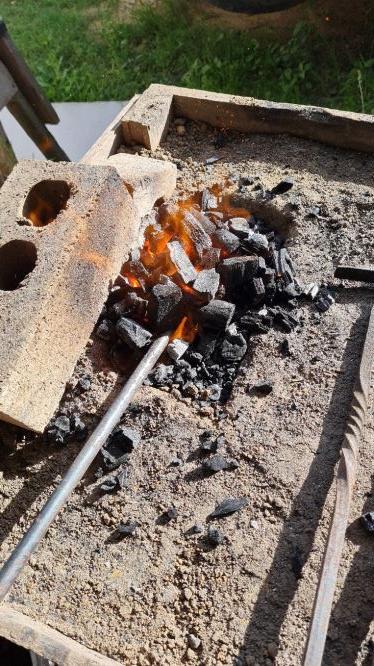
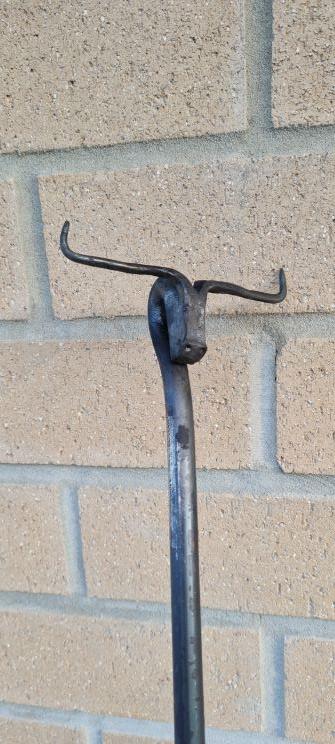
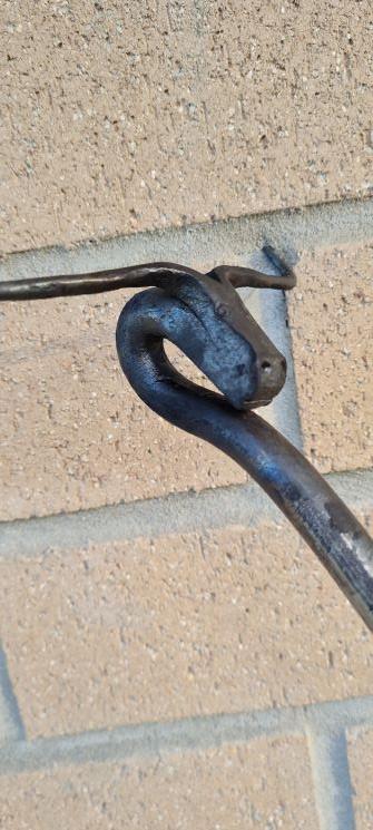
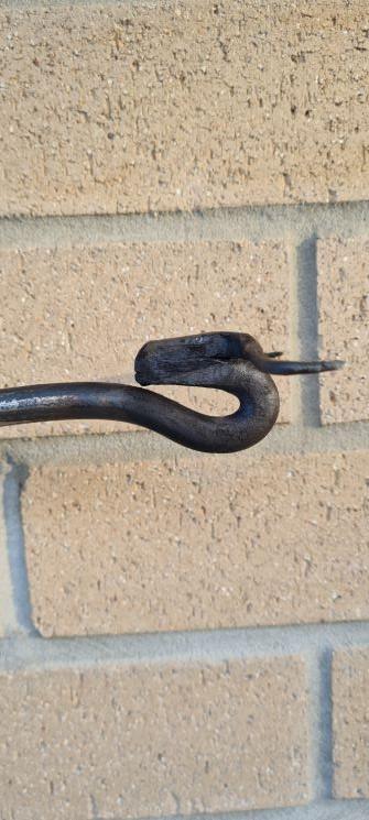
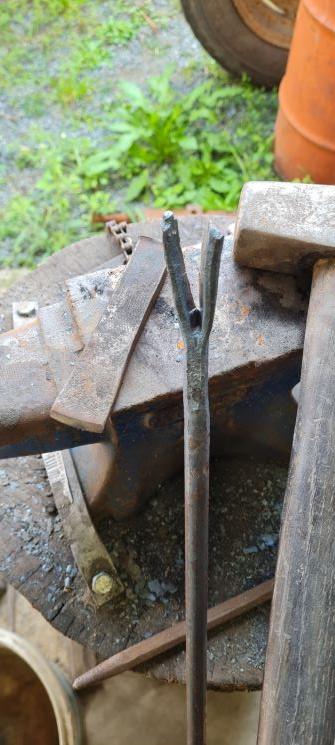
Looks great Das! Like a gator from the gates of Hell!! I finally got back to the shed to do some forging today. I'm making a camp oven lid lifter and the handle is my first ever Long horn head. This is where I left off a few weekends ago so today I fired up the JABOD. Here's the pic Frosty asked for last time I'm bad at remembering to take photos so the next shot was after drawing and tapering the horns and turning back and forge welding the head. I think the weld took but it's not critical in this application. Then I got REALLY bad at remembering to take photos so here it is all finished I'm over the moon with how it turned out!! Credit to Darryl (Ausfire) for the inspiration for the design. I got to see him demo this type of long horn head last year when I took my family to the historical village at Herberton where he is curator and blacksmith. I took lots of photos and some video and I was able to refer to them today. A great afternoon's forging! Cheers, Jono.