Another FrankenBurner
-
Posts
616 -
Joined
-
Last visited
Content Type
Profiles
Forums
Articles
Gallery
Downloads
Events
Everything posted by Another FrankenBurner
-
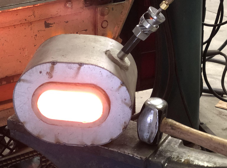
 yotebuster, the mini forge I used for the hammer is a 2 inch circle, cut down the middle and separated by 2 inches. The forge depth is 6 inches. We have made a 3 inch version (3 inch circle split by 3 inch) and a 4 inch version. We are playing with 8 to 9 inch depths for a little extra. I have not powered a forge with the 1/4" super yet. I just now got one put together so the next 2 inch forge will get one. Right now, the two inch forges are powered by detuned 3/8" burners. No wonder I have always felt so welcomed here. Birds of a feather.
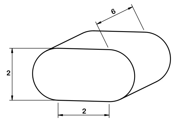
-
Thanks Mike. Part of what I like about some forums is the constant checking of information. Anyone can say anything they like, intelligent or otherwise, and then the information can be questioned by the knowledgeable. Thanks Jennifer. Solid fuel forges are hard to compete with when it comes to localization of heat. Controlled fire size, higher temperatures, and the ability to shield some of the stock from the heat. I like liquid fuel forges in their ease and cleanliness but I will probably always have a solid fuel forge as well. I do like the mini forges. The new guys tend to like to build gigantic forges so they can forge anything they may envision in the future (anvils maybe?). When I was new, I made dozens of s hooks, leaves, wall hooks, punches, and eventually tongs. Taking a lot of time in several heats to make each as I was learning how to move metal and use the heat. All of that can be done in a mini forge and cost much less fuel to do so. To contrast the idea the new guys have, I like pushing mini forges to their limits. I recently forged a 2.5 lb hammer in a 43 in³ forge. I am also headed in the opposite direction, producing a burner which is larger than I need for forge use. OrganIQ, that is some interesting stuff. I would like to see some pictures if you can. When you say air, are you meaning as an insulator? Voids in the refractory? You said "the many AIR bubbles turned out to be the best thing for the final air/fuel ratio" and "consistent airflow through" which could mean airflow through the fuel which confused things for me.
-
You don't like the orifice to be as large as the mix tube? Yeah, that's what I mean. Only one little zero making so much difference. Thanks Mike.
-
Propane Ribbon Burner forge plans - Comments?
Another FrankenBurner replied to mtodriscoll's topic in Gas Forges
I cut kiln shelf with a DeWalt diamond blade for dry cutting masonry with a 4 1/2" angle grinder. It cuts easily but I only recommend it if you have a bit of experience with an angle grinder. Have a good fitting respirator. I like the idea of a forge which splits and continue to work on the idea but suspending the refractory in the top half is not easily accomplished if the refractory is thinner. -
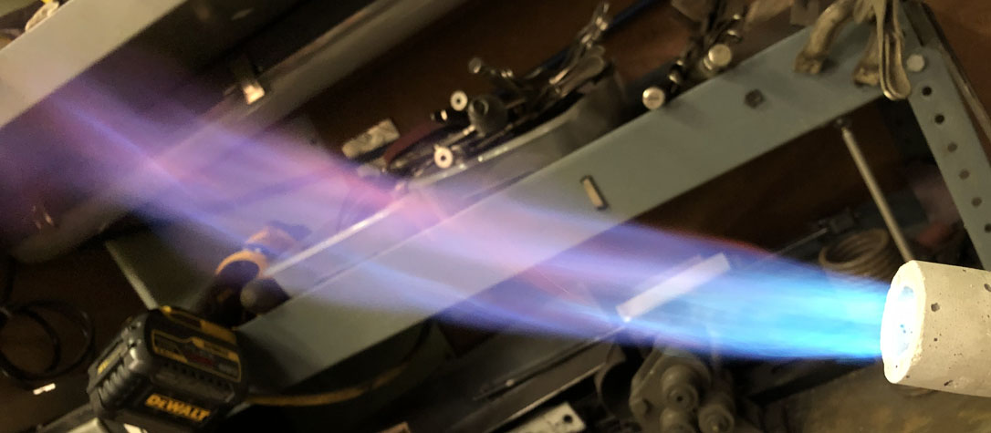
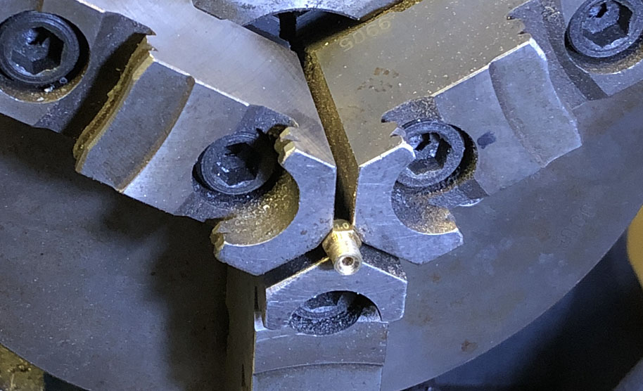
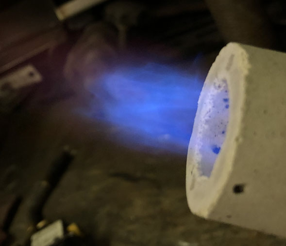
I will have to play with the propylene. Sounds like fun. I was out in the shop, trying to dial in a new burner nozzle combination in the 1/4" burner size. I had it pretty close with one orifice but wanted to see it with the next lower orifice size. I expected to see this: What I ended up seeing was this: "What is wrong with my orifice?" I thought. Hmm... Works pretty well without the burner. A little rich though. The 900lb chuck daintily grasping the tiny printer nozzle to make new orifice assemblies. Preferably minus the leaks. The new 1/4" burner ended up being happy with the 0.8mm(≈0.315in) orifice.

-
I have not used propylene with any of my burners.
-
That is a great point that I tend to overlook. My preferences are based on my application.
-
I thought of a problem with my thinking. I said that your ejection velocity would be lower and talked about the nozzle size. I wasn't totally wrong. The ejection velocity per pressure will be lower, however, because of the lower energy output, you will be running higher fuel pressures to compensate. This makes your ejection velocity higher per energy output. Mikey burners use a smaller orifice running a higher pressure compared to the Frosty T's running the larger orifice at lower pressures. They can both output equivalent energy but the Mikey's eject at higher velocities when doing so. Both ways get the job done. I currently prefer the slower end of the spectrum and have designed my burners to slow things down as much as I can without lowering output.
-
You want less output from your burner... Tim Allen is frowning somewhere. Actually, you have a fun line of questioning. Good for thought. Most guys are trying to push as much output down the pipe as possible. This means we are all fighting for as much air induction as possible. Where you are not demanding the max, you have surplus air. You could get away with quite a few things that the others can't. First, what size forge are you talking about? Most likely you could run two standard 3/4" burners turned down. Though, I would follow others advice on that. I have only played with the 1/2" Frosty T's so I don't know about the turn down range of the 3/4" burners. You are branching into your own thing a bit here. I have used the 023 mig tips in the 1/2" Frosty T's. You want an in between burner? You might try the 030 mig tips. When you put a burner in a forge, it is pushing through more resistance so it will have a harder time inducing air. How much so depends on the burner design and the forge design. I have played with a lot of combinations and most of the time, the change is fairly minimal. Where you have surplus air, it is nothing to worry about. You can tune it to compensate. It sounds like you have gotten it to burn cleanly by positioning the orifice closer to the throat to induce less air. Nice job. So long as the fuel air ratio is correct, mixed well, and delivered at a high enough velocity to not flash back into the mix tube, you are doing good on the combustion end of things. Your ejection velocity will be lower so your flame may ride deeper in your nozzle, potentially over heating it. If so, you can go to a tighter nozzle like a 3/4" coupling. You are correct, the orifice position fine tune's the air volume in the fuel air ratio. The orifice diameter determines fuel volume in the mix ratio and the total energy output per fuel pressure. Could you post a picture of your flame? I have not tried an 023 tip in a 3/4" mix tube and I would like to see what the flame looks like.
-
It really depends on your heat requirements. What you want to heat and how hot you want it to get. If you are wanting more specific help, you can post your burner and flame pictures in Burners 101 to get an evaluation and ideas for improvements. Then you can head over to Consolidated notes for new forge builders for a synopsis of building a forge with ceramic wool. You can also head to Forges 101 for much more detail. Curiosity here, why do you have a dozen burners? Are they all different types? Do you only have the small firebrick forge?
-
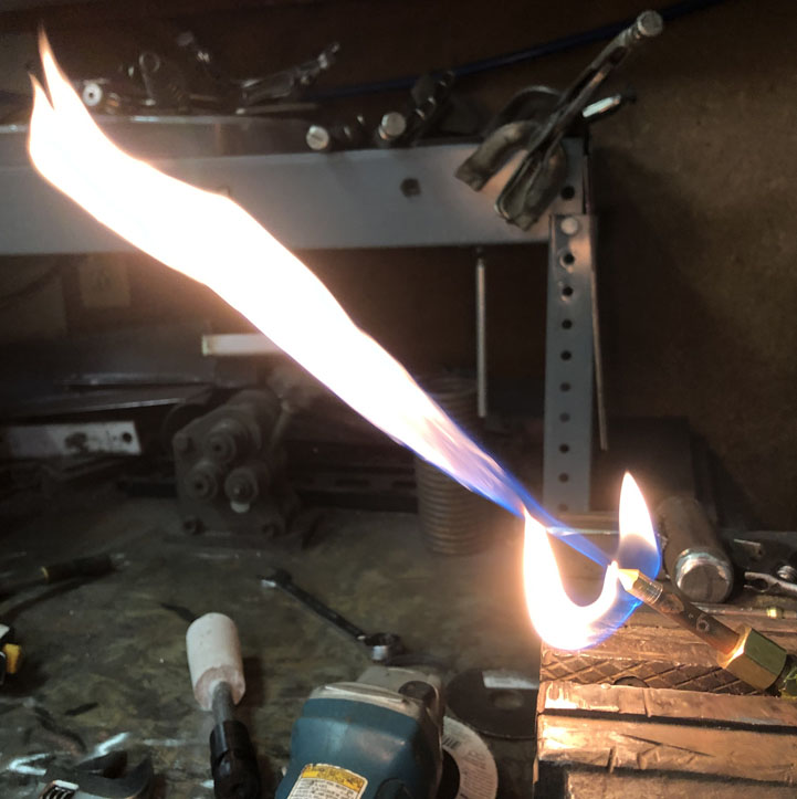
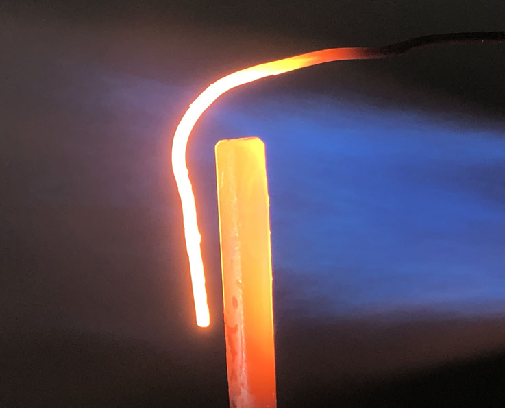
Are you using the wire color as a benchmark for your burners or are you just trying to understand things? A forge will never get hotter than the flame. Again though, the theoretical limit of propane/air is near 3600°F. While we will never hit this temperature, we don't have to. That is a lot of headroom for our imperfect flames. Like ThomasPowers, I have melted steel in my forge. Hot enough for the girl I go with. If I pull that same burner out of the forge for heating metal in open air, the metal will never obtain the same kind of temperatures. There is too much loss. I have not payed much attention to the maximum temperatures I can obtain in open air because of this inefficiency. I went out to the shop and fired up the test rig to cook some wire, just for you. It's hard to take pictures of as both metals and the flame are light sources but this is a fairly decent representation of what I was seeing. I always like the blue and orange. Ambient temperature was 43°F. This is bailing wire and 1/4" round stock. They had been in the flame long enough to stabilize. They weren't going to get any hotter than this.
-
You did not remember it incorrectly. Or were you saying I was talking about something incorrectly? I have seen higher velocities/flow rates with the printer nozzles when compared to a same sized orifice mig tips. I built a testing rig to compare them when I started using the 3D printer nozzles. I was originally concerned the 3D printer nozzles would not produce the proper jet as their orifice channel is much shorter. They ended up producing a nice stream. I also started shaving length off of mig tips in steps to test the effects, like Frosty does to tune his burners. The longer the channel, the higher the resistance, the lower the flow rate. Same here. I like discussions, not arguments. I don't want to discourage. I especially don't want to discourage math. I am not trying to give you a hard time. The intake section, I could not tell what it was describing. The way it is written confused me. Even for area, 1.5-2 x the ID of the mix tube is confusing. For 3/4" pipe, are you calculating 0.824 x 2 = 1.648 in² or are you meaning multiply the area of the mix tube by 2? ( 2π(0.824/2)² ≈ 1.067 in² ) Why express things in rough formulas, rather then giving rough measurements? Is this so that the advice could potentially apply to other sizes of burners? The mig tips were two different manufacturers. I wonder if I bought another brand, if I would find a third size.
-
Don't worry, I haven't been gone that long. I may stay up late into the nights thinking about them but there has been no romancing with the burners over here. Poke fun away. I'm sure I'll add more fuel to the fire soon enough. I keep trying anyway. A glazed flame job would be cool. The shark mouth nose art would be pretty cool too.
-
I tried to distill burners 101 in a similar fashion. Somewhere along the way, I realized that each burner has its own dimensional happy place. The only rule of thumb that seems to fit most of the time is the 8-9 mix tube length. I have found that even mig tips vary a good deal. I have an 035 tip which measures 0.041 and another which measures 0.047. If your target is folks who watched YouTube, concluded that a burner is just a little hole spitting gas down a piece of pipe, and put something together based on that, most likely they don't speak burner. As such, nozzle, mix tube, and flare may mean nothing to them. If I didn't happen to know what you were talking about already, there is a good chance I would have no idea what you were talking about. Your intake section, are you referring to the reducer diameter on a linear burner? The nozzle section math doesn't add up. The ID of 3/4" schedule 40 pipe is 0.824" + 1/8" = 0.949". That is less than most use and nozzle overhang can vary based on fuel/air mix velocity, nozzle ID, and back pressure. Mostly, there is just not enough information to demonstrate your points. I'm not trying to knock your idea. It's just not as black and white as all that. If it were, burners 101 would be a lot shorter. I think you could provide more information on each point to give a ball park sense of each bit's purpose in the machine. It could illustrate that there is more going on than just fuel down a tube. You could also point out that there are several known good working plans and it might be easier to just build one of those. If they want to continue running with their own thing, direct them here. Helping others with 'on the fly' burners requires even more understanding. Even still it involves a bit of extrapolation. As Mikey put it, these are puzzle burners. We can all help with what we know and we can all learn from the puzzles.
-
Full ceramic burner, now you are just talking dirty. This is a family friendly forum. Thanks Frosty, I missed being in burner land.
-
Welcome dian. A better place for this line of questioning is probably in Forges 101 as your questions are forge related. The flame temperature of propane/air can be much hotter than 2200°F. The theoretical limit is 3600°F. In open air, most of the burner's heat is blowing right past your work. Your work has to gain temperature from the little contact of the small portion of the heat hitting it. It is also in a colder ambient environment so its heat loss is high. A forge is just a heat trap. It loses heat, the same as your work, but it is an insulated container so it loses it slower. It is able to increase the temperature of it's environment closer to the flame temperature because of this slower loss. When you place your work into this much hotter environment, it will gain in temperature faster and lose heat slower.
-
The nozzle is also missing a step if we are comparing this to a Mikey burner.
-
We shouldn't be too hasty when throwing out ideas. I bet the wife would prefer I came in from forging smelling of cool mint.
-
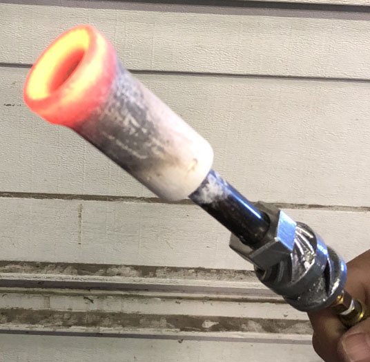
Thanks Mikey. I have a lot to learn with ceramics. Right now I am playing with different materials and mixtures and firing schedules. I have not attempted a ceramic liner yet. I am starting small with tiles and nozzles for my abuse testing. I am looking forward to messing around with ceramic forge lining. I have not run the nozzles long enough in open air to see if cracking was an issue. The photo above was pulled out of a hot forge right after shut down. The smooth finish is what came out of a 3d printed mold. That nozzle cracked because of a stress riser created by a seam in the print which we have since eliminated. I have tried burners faced upwards across the ceiling of the forge with a few forges. A couple of them are pictured in this thread(Page 9 and Page 11). At the moment, I prefer burners pointed down. I have grown accustomed to using the blast zone hot spot when needing to heat small sections without heating the whole thing too much. With the upward pointing burners, I placed stock near the opposing side from the burner as it was the hottest spot but it was a wider hot spot by then. Complaining about more even heating, what is wrong with this guy? I am not done playing around with upward facing burners as I see many advantages. Thanks Jennifer. Don't you have an axe to grind? Thanks Scott. Have you made any headway with your experiments?
-
Thank you Mikey. I was surprised by this. It had nice timing. Some health stuff had slowed us down lately but it has all resolved for now so we are back to tinkering. We have started playing with different ceramics. Zirconia has a nice low conductivity and is happy at high temperatures so we plan on experimenting with nozzles and if it goes well, potentially forge lining. We'll see. I am still a big fan of the mini forges for any work that will fit in them.
-
I do use 3D printer nozzles as orifices. Member G-son suggested it, I believe in burners 101, but I could not find the post. I did find 3D printed plastic burner experiments (photo heavy) - Page 22 which I said I had started using the printer nozzles and what I liked about them.
-
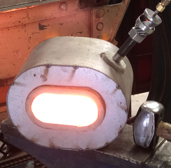
I have not payed attention but no ozone that I have detected. I don't have an accurate temperature reading but they are hot enough for me. This is a 3/8" burner with an 0.031" orifice running below one psi in a mini forge. Both the forge and the burner are older designs. I am currently working on updating the 1/4" burner for a forge this size. I still haven't built a micro(nano?) forge for the 1/8" burner yet.
-
If you are going to plastic bag your tools, do not forget a desiccant. Otherwise, the bag can exacerbate the rust problem.
-
Naturally Aspirated Ribbon Burner. Photo heavy.
Another FrankenBurner replied to Frosty's topic in Ribbon Burners
If you are going to scrap it otherwise, it would not hurt anything, except your tools. I've destroyed a carbide tool trying to modify kastolite after firing. If you could succeed easily, you would gain more data but if kastolite is easily worked after firing, something was wrong in casting/firing. (If you used kastolite) I wouldn't put a lot of effort into it. Wood and plaster are easier prototype mediums. -
Naturally Aspirated Ribbon Burner. Photo heavy.
Another FrankenBurner replied to Frosty's topic in Ribbon Burners
Back on page 19-20 Dan was playing with a ribbon burner with 1/8 inch ports and he landed at 123 ports. He was using a different inducer so it is not a same same kind of thing but I figured it was food for thought.