Another FrankenBurner
-
Posts
616 -
Joined
-
Last visited
Content Type
Profiles
Forums
Articles
Gallery
Downloads
Events
Everything posted by Another FrankenBurner
-
I’m not qualified either. While I studied what I could, trial and error led most of the way. The burners don’t really have a name. The first time I heard the term vortex burner was in this thread and it was referring to a new Mikey design. How about twirly birds?
-
I hear Tim Allen grunting again.
-
Ron told me to send his best. I am a smaller is better kind of person. I found a good woman who has the same mindset. A smaller burner doing the same work is good stuff. A smaller forge taking that smaller burner just makes me happy.
-
Ron doesn’t know. Last he knew, it was handed down to the son years ago. He lost contact at that point. He tried to convince me to sell what I produce as there is now a void.
-
He lives about an hour from me. I apprenticed with him for a couple of years. When I first visited him, I peppered him with burner questions. Michael Porter and Jerry came up in the conversation. He remembers you. I will let him know you said hi.
-
I visit him. He always has a smile when I see him.
-
That Apollo ribbon burner is meant to be air supplied with a 6 inch 440 cfm centrifugal inline fan. A big fella.
-
I have moved over to 3D printer nozzles with my burners. Higher velocity, higher induction, higher output per pressure. I also like that they are brass so they are easier to turn as I braze them into ¼” stainless brake line. I’m not suggesting they are better. They work for me.
-
 Uncle. Uncle. I yield. I shall refer to them as vanes going forward. Thank you for the continued thought and education. Hard to believe that was four years ago.
 -
I have been known to use ½ inch of kast o lite. I now prefer 3/8 inch. Maybe you got the idea from me. Recently, on page 125 of Burners 101, I posted a CAD drawing of someone else’s forge idea. I had ½ inch kast o lite in the drawing. Maybe that’s where you saw it. Plistex is painted on in a few thin layers. The benefit of the D shape forge is the increase in floor width to forge volume. (Compared to a tunnel forge) The shape that you posted is more like a box forge with a vaulted forge on top of it. Large forge volume without much benefit. The larger your volume, the more expensive it is to run. Tall and narrow usually means extra unused forge volume and uneven heat patterns. I personally prefer a flat bottom oval forge for the flow patterns and wide floor but several people like the D shaped forge. Usually that is either a half circle or maybe a little bit of side wall. Burner orientation is also important. As Frosty stated, you don’t want to create back pressure. Imagine aiming the burner so it runs along the wall or floor that spirals around the forge in as long a path as possible.
-
A few years back, I took a peek behind the curtain. It was a brief but profound visit. I think each person’s experiences are their own but I’d be glad to share privately if it might bring some comfort. It brought me comfort when I needed it. That is for anyone interested but in private only. That’s all I’ll say about it here.
-
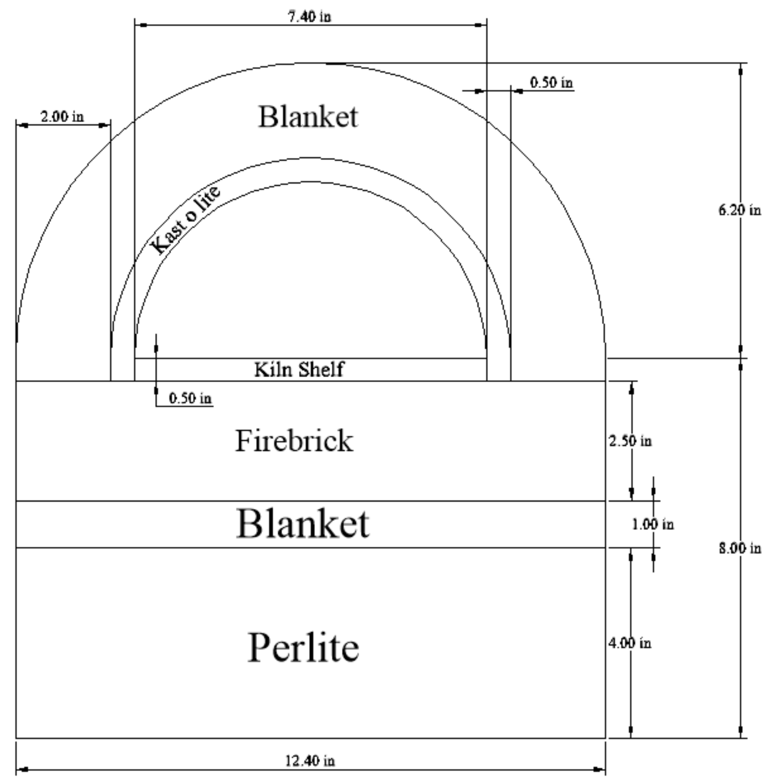
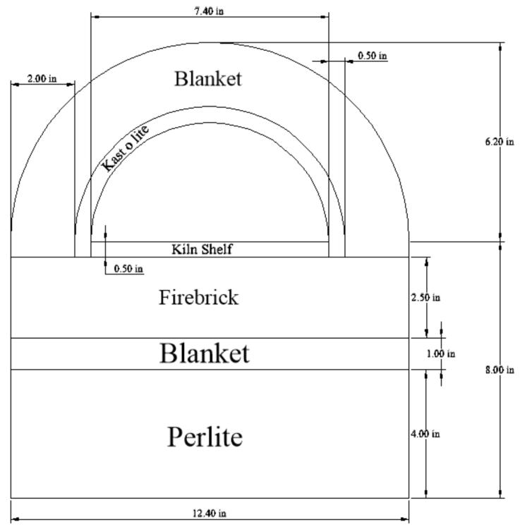
This is my interpretation so far: If two inches of blanket and a half inch of kast-o-lite are lining the forge. The volume of the forge would be half the area of 7.4" diameter circle multiplied by the length. Click the image to enlarge. Hope it helps.
-
Your lowest measurement of 19.5 width is incorrect. It will be 12.4 wide because of the curve. Radius x 2 or diameter.
-
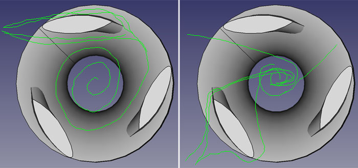
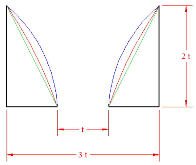
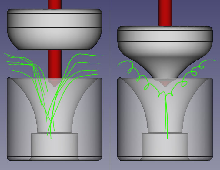
The answer to this being a good visual is no. The concept, yes, kind of. I had this same idea before I started playing with smoke. I even experimented with several iterations of airfoil design based on this idea of air flow. The air does not enter the burner as the penny enters the funnel. The air is pushed from the high pressure zone (outside the burner ambient air) to the low pressure zone (the throat of the burner) in a short path. The burner is not inducing enough air to get the air outside the burner swirling. Here is another rough drawing to demonstrate the difference: On the left is the penny funnel idea. How I thought it worked until I played with smoke. On the right is a representation of the smoke paths I witnessed. Smoke moving perpendicular to the ribs, some of which goes behind the ribs. I think the canted ribs cause just a little bit of movement in some of the air but all in the same direction. This little bit is all that is needed to nurture the vortex. As you can see, the ribs are in the way. I have induced more air with small round ribs, but the burner did not perform as well. I have compromised some air induction for better mixing with this rib style. This is not to say that the reduction shape, specifically the trumpet, is not important or that it does not affect vortical flow. When I was playing with shapes, I made one of those tornado tubes that kids build with 2 liter soda bottles except I found specific shaped bottles and printed a shaped/sized orifice between the bottles. The trumpet shape did the best, by far. I always found the shape of the total vortex interesting. I have wondered if part of the greatness of the trumpet shape is that it somewhat matches the shape of a vortex. Potentially limiting dead air space which just slows the flow down. Maybe? It's hard to say. You could play with some smoke. As to the hard to light with fluttering, what if you have caused such a dramatic increase in air induction that you are now trying to coax a very lean flame? It is a possibility. Make sure to fully test something you already have to learn as much as possible before making changes. A lot. A have spent a lot of time on this. I still haven't figured it all out. It can get deep, fast. For simplicity, let's assume Mikey's above posted ratios (3:1D, 2:1L) and a simple single arc. Both the center and radius of the arc can be played with: Big difference in performance among just those. We can also play with length, diameter, and multiple arcs or splines to complicate things. I trial and error my way through it. I'm not educated enough to understand the why's of this one.
-
Poor drawing alert. I could have done worse, but I couldn't find any crayons. The inner cone increases induced air. Originally, I added it thinking that the volume that it takes up was just dead air space which may have caused turbulence with incoming air. After playing around with smoke testing, I discovered that it causes vortices in the incoming air. Without it, the incoming air follows curved paths towards the jet and down the mix tube. This was a major improvement in the burners. With how much extra air it entrained, the orifice size was bumped up, a more aggressive nozzle was designed, and its output increased.
-
By inner cone, are you referring to the cone of the orifice block? (Frosty coined it the aerospike)
-
I like what is happening in the thread today. Talking ideas. I'm always lurking. Been busy lately. If only I didn't have to work. My free time has been spent building an attachment for the lathe. It's for burner work, to play with some ideas. No experiments lately though, so nothing useful to contribute. I did play with airfoil design for the vanes/ribs with several iterations. Then I did some smoke testing and realized that I had the induction streams all wrong in my head. The beginning of the mix tube (the throat) is a low pressure zone. The atmosphere outside the inspirator (the thing I print) is at a higher pressure so it pushes air into the low pressure zone. Imagine straight lines from the perimeter to the center, kind of. Air is not being gracefully pushed along the vanes/ribs as a wing through air. It is being pushed around the vanes from perpendicular. The little bit of sideways movement is all that it needed to nurture a vortex. After the head slapping realization, the rib design went pretty boring to be as streamline as possible while still providing a little sideways movement. Anything else caused more drag than its effect was worth... for my goals. Hopefully that made sense. If not, tell me I am horrible and I will take more time to attempt to articulate it more gooder. Same here. Pesky principles. I designed the burners in FreeCAD. It's freeware so it may not be as intuitive, maybe a little clunky here and there. I have not had any ideas that I could not model accurately. The latest version is miles ahead of the version I started on.
-
I built a shed. When installing siding, I realized a 2 inch discrepancy. I am a measure 3 times, cut once kind of person. Also a hobbyist machinist. Two inches was unacceptable. I had to get to the bottom of it. Turned out, the open reel measuring tape that I was using had two different sides. One in feet/inches and one in feet/tenths of a foot. A tenth of a foot looks close enough to an inch that I never even noticed. How I got as far as I did without noticing is a mystery. I had a good laugh, learned my lesson, and covered my shame with siding. Glad it wasn’t critical.
-
Not having to have two sets of tools, which look almost identical, would be great. It’s especially nice when I get to work on equipment that uses both. Having to teach the new guys fractions is generally entertaining. Hey, I have 49/64ths, I need the next 64th down. Wait, you have to be good at math to run a tape measure? I once got a call out of “half inch plus three little ones.”
-
We are slowly converting. Inch by inch. Still seems like miles away though.
-
I prefer this. I ditched the pipe threads for a slip connection as the threads were often not concentric. Once the threads are out, why use iron pipe that is often not actually round and has a welded seam? You can also go to thinner wall to make a lighter weight burner and go to stainless if you want to get fancy. I removed the seam in an earlier pipe burner I made. It made a difference but it was a smaller difference than I expected. It’s still worth trying on your burner though. If you go to thinner walled tubing with the same OD as the pipe you are using, you will see big changes. This would be increasing the throat diameter. Throat diameter is important enough that several of my dimensions are ratios of it.
-
There are many drawings posted throughout this thread. A person could search through the thread and link to them. I don't want to make it too easy. The closest I can think of without 3D printing would be a hybrid burner with air inlets cut diagonally. On the previous page, I posted an image of the parallelograms I envisioned as cutouts. You are making progress. Science is fun. How many times science has smelled of burnt hair. We also have evidence that not having direct easy access leads to more experimenting and from different minds. A fantastic situation. Look at what you all have done. Something quite different. Thank you for posting what you have done. Even those wishing to clone them will come up with something a bit different. More data is good. A person could comb through this thread to get all the details and get very close to what I have done. What's the fun in that? Similar but different. Thank you for posting what you have done. It is looking good. A cousin maybe. Do post more. Images, observations, questions. They are all wonderful. Keep up the good work. Me too. My definition has changed along the way.
-
All this burner talk in the forge thread. This is the 101 material? The wife says when she starts to smell smoke, she knows I'm a million miles away going a hundred miles an hour. I have just recently started playing with burners again. I stopped tinkering for a while. The burner was working so well that it was time to take a break to spend more time swinging a hammer. The burner I have been using is the 3/8" nominal (0.675 throat) burner head on a tapered mix tube with a large step nozzle. It has been working great. The tapered mix tube made a giant leap in induction. I had to choke the burner down as it was too oxidizing to forge weld which means I get to play with orifice size some more. I am very pleased with the burner. I have started on my next adventures which are tapered mix tubes feeding multiple ports. NARBs, shower heads, simple splitters and whatever else comes up. Using the "burner" as an inspirator. A fuel air pump. I have not played with the tapered tube and the manometer enough to speak with experience but in my current mind's picture of things, the tapered mix tube's purpose is to do the opposite of what the throat is doing. The throat constricts, causing an increase in velocity and a decrease in pressure. We want the low-pressure zone to induce air. The tapered mix tube is decreasing velocity to increase pressure. Instead of relying on the velocity of the FAM, we are increasing its pressure from the low-pressure zone in the throat. In my little bit of playing with NARBs, without the tapered tube, there is a large discrepancy in stream velocities across the ports. Faster velocities nearest the edges. I think the FAM is coming into the plenum at high velocity/low pressure and anywhere that it slams into a wall and slows down, it increases in pressure (inefficiently). If my thinking is correct, using the slower higher-pressure FAM coming from a venturi will cause more even velocities across the ports. It would allow the burner head and mix tube to act as a FAM pump, an inspirator. You could also push FAM around some bends, down longer sections of pipe, etc. Sacrifice some throughput for orientation options or port configurations. Time to stop talking and start experimenting. Maybe I can prove all that wrong and update my thinking.
-
This line is why Thomas stated the Kalmar line line.
-
Flame velocity… that topic makes my head hurt.