Another FrankenBurner
-
Posts
613 -
Joined
-
Last visited
Content Type
Profiles
Forums
Articles
Gallery
Downloads
Events
Everything posted by Another FrankenBurner
-
For close enough work with circumference, I multiply by three and add ten percent. For the 8 inch circle, 0.8+24. If I need to be over, I add 15 percent. 1.2+24.
-
You are thinking too hard. We can be friends. I thought I had gathered that the pipe actual dimensions were very close between the two standards and that threads were the big difference. In which case, if wall thickness are also fairly close, you can just build per the instructions. Building another forge is just part of the blacksmith way I think. Plot to build that perfect forge and as soon as it’s done, start plotting the next with improvements.
-
If your intention is to work on large/long knives, long and thin is fine within reason. Just use two smaller burners. Unless the current forge is built poorly, why build another. If you want to do more generalized forging, long and thin isn’t as much fun to work in. The jet gap is a starting point for tuning. You don’t want to go crazy on over sizing the air inlets or burner performance may suffer. As Frosty stated, it’s a ratio game. As far as I understand it, nominal pipe sizes are close between the two standards. If that is the case, select the next size up from the mix tube. If you want a 20mm burner, use 25mm air inlets. If you want to build 25mm, use 32mm inlets. If you give your forge internal volume, you may get recommendations on what burner(s) will work well.
-
I don’t know about Canadian law so it may be different but you want to call around to hvac and appliance repair companies, not suppliers. The repair companies actually use the refrigerant and have the empties. My company sells them for scrap otherwise. Lots of them. If you do get one, make sure it has been evacuated. We evacuate them and drill a hole in the blow plug.
-
I started with a refrigerant cylinder because of Ron Reil’s mini forge page and I am an HVAC guy. I think the forge would be awesome for a bladesmith but for general smithing, they end up a bit small in inner diameter and way too long for my liking. They could be cut shorter or walled off but you still end up with 3.5-4 inch inner diameter which yields a very narrow floor space. I do prefer the blanket, kast o lite, plistix way of building forges but now I make my own outer shells with sheet metal as I can make whatever I want. I like a lozenge shape because of the flat wider floor while still keeping internal volume lower. I also like no longer/deeper than 8 inches. With the refrigerant cylinder, I was always heating way more of the stock than I could work.
-
Off the top of my head, I believe the insulated bricks are 8 ounces ish and the hard bricks are 4-8 lbs. The hard bricks are less expensive but don’t make for a good forge. They do work but you will spend more on fuel in short time then the cost of insulating bricks. I have both, I use the hard bricks as backers for torch work and other odd hot jobs like that. I can take pictures of both of you like. The insulating bricks are porous with large bubbles.
-
 Hello Andrew. Welcome to the site. If you like to learn, it's a great place to be. My original intention was to make my experiments public. Both, so others could learn with me and so that wiser others could point out my errors or offer suggestions. At one point I did pursue a patent, but I remembered that original intent and stopped. This thread is now prior art so "my" burner belongs to the public. If clones are eventually mass produced, I would feel accomplished. Until then, I'm just a guy in his garage having fun. Hopefully the clones are decent and inexpensive.
 -
Ron Reil's main forge is massive. I have spent many hours in front of it and never needed its full potential. I believe it is 8 inch internal diameter, 24 inches long for ~1200 in³. It has four 3/4" burners. Though usually only the first one or two are used. It was designed with minimal mass so that it would heat up to high temperatures quickly so not much in terms of "storing" heat. He no longer employs the sliding back wall. If you are after fuel savings, it is not the direction I recommend. I have built many forges and quickly learned that I like the smallest forge that will do the job. My go to forge is 43 in³. It stretches the propane. I have forged a 2.5 lb hammer with it, mostly just to do it. I fought heat distribution a bit, having to turn the stock often, as the internal height and stock height were close. For most other day to day things, it does exactly what I need it to. When it doesn't, I fire up whichever forge does. I would not forge weld with poor heat distribution. Though, most things I forge weld are not very large and the little forge does great with that. The biggest things I have found with forge welding are hitting the minimum temperature and not being oxidizing. A smaller forge will hit that temperature with less fuel than a larger forge. As to forge volume and fuel consumption being linear, nope. As Frosty has pointed out, even forge dimensions can drastically change fuel requirements. More length, more friction. Even if a forge was dimensionally scaled, it would have more or less surface area for loss. My first forge was a freon cylinder forge. About 3.5" ID by 12" length for ~115 in³. It originally ran with a 3/4" modified sidearm burner. I eventually replaced the burner with a 1/2" burner which used less fuel and the forge was able to obtain a higher temperature. When the large burner was turned up beyond a certain point, the flames coming out the doors got bigger, but the forge didn't get much hotter. This forge always had a large temperature gradient from the hot spot out. Its length versus its other dimension was too different.
-
I presented the exact same angle (2.386°) in burners 101 quite a while back, had a triangle drawing and everything. If remembering correctly, the 1:12 taper came from Frosty, years ago, out of some burner patents or technical papers. Though, it was describing a tapered mix tube not a retention nozzle. The angle is important in that the included angle is almost 5° which I was told is the fastest you can expand without causing stream turbulence. Venturi tubes often open at 5° after the throat. It may have been expressed as 1:12 taper for the turner. At some point, I found a chart which listed different taper/lengths and their DMS equivalents for cutting on the lathe. I don't know for sure. As to the nozzle in our case, the wall thickness of the mix tube creates a step which causes turbulence before the taper comes into play. I have found the nozzle taper is not very critical if flame retention is the only desired function. Agreed. I think that is why Mikey now uses 'flame retention nozzle' instead. It's been in use a long time over many sources though. Any idea's on alternative nomenclature?
-
I just went and downloaded it to test the link. It downloaded successfully. If you would like, you can PM me your email address and I can send it over.
-
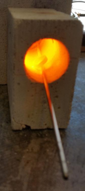
I have made a few, on the fly, for odd jobs that didn't need to waste propane. Even with the Morgan K26 bricks, they crumbled fairly quickly. I have thought about a sheet metal skin and a coating of plistex to see if they would hold up longer. Here is bad picture of a half brick forge for a ring I was working on:

-
I did something similar to what you are describing. The compression fitting had an insert stop ring which I had to drill out to a tight tolerance so the mig tip central alignment would not have too much slop. I also made a narrow cut in the compression ferrule to prevent it from seizing. Though I still don't tighten the fitting tight. There are some pictures of it on page 11. I have also modified a brass reducer bushing to make a rough collet. Drill out the inner threads to match the orifice tube and then cut slots through the threads. This way when tightening the reducer fitting, its tapered threads compress the fitting and clamp on down on the orifice tube. This wasn't my idea. I believe I first saw it done on the modified side arm burner sold by high temp tools.
-
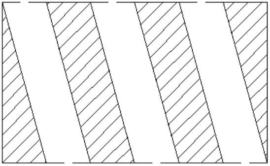
I had thought about the parallelograms in the past. At the time I was thinking something like the hybrid burner only with diagonal cutouts. I was going to print a scaled paper cut pattern. Something like this: If anyone is interested in doing so, I can send a scaled printable pdf so long as I know the OD of the pipe you are working with, and the desired length and angle of the cutouts. I have been curious about it for a while. As to the noise level, even with full baffle walls, it is more the constant drone in the background that can get to me. The forge noise and my tinnitus play tennis together I think. I shut the forge off and something in my mind relaxes. Almost always, I am wearing hearing protection so it doesn't bother me. It's usually just when I am in the forge with someone else and not wearing the muffs. If we start using jet engine parts, I will have to get better hearing protection. Hefty, I think that will make a great hand torch. It's a healthy flame. I have a 3/8" version with a bent angle iron pistol grip. It is very handy. I have to admit, my mind took a double take on your baffle wall image. I'll leave it at that. As to the baffle wall, this post in forges 101 talks about it. Keep on tinkering. It is good fun.
-
I sure don't mind. I think it's great. I'm excited for you. Straight off the mix tube is fun but once you put a nozzle on it and step up the velocity, it will roar. I think I once called it an angry little jet. You can't help but smile when you hear it the first few times. I am now playing with ribbon burners to quiet that roar. After several hours, the noise gets to me. Very important, try to keep everything axially aligned. In your picture, it looks like that is not the case which is why the flame is not symmetric. The orifice and mix tube alignment being the most critical. A small misalignment in them can severely compromise the potential. I saw your question in burners 101 about beveling a Mikey hoping to get more vortex. Did you try it?
-
That is a bummer hefty. As you said though, you learned heaps. Knowing more about your burners will make future troubleshooting easier. When I made some Frosty T's with the lathe, I threaded the tee onto the mix tube and centered the mix tube. So long as the mix tube is concentric, the hole will be drilled In the tee, centered on the mix tube, no matter how far out the tee is. Plus there is no measuring to determine where mix tube center happens to land on the tee. If I am remembering correctly, Frosty suggested it to me. It almost takes the work out of it. Nice dig Tink. Interesting find. Over thinking Teflon tape... we can be friends.
-
Your presumption is correct. The mig tip is a stream shaper. We want that fuel to be in a fast collimated stream down the middle of the mix tube. The mig tip is also a metering device. It only allows a certain amount per pressure. Right now you have an uncontrolled amount with who knows what kind of shape, potentially causing all kinds of turbulence. Too much fuel and not enough air. Until you fix it, there is no point in attempting to tune. I have used gas tape and thread dope. Both work. I'm not sure of the reasoning that you read against tape. Perhaps because if it is installed incorrectly, pieces of it can make it into the gas way and plug the orifice. If you go the tape route, make sure not to tape beyond the last thread on the orifice inlet side. Nice job. You are getting close. Soon you will be thinking about shaping metal instead of about burners.
-
"You mean I should back the regulator out every time! Why?" I like valves. Bottle to regulator, to ER shutoff ball valve, to hose, to second shutoff ball valve, to idle ball valve with bypass needle valve, to individual burner needle valves, to burners. Control freak maybe?
-
Also, don't try to close the needle valve with extra torque, after it has seated, in an attempt to get it to stop flow. There is a reason the knobs/handles are so small. Metal needle, metal seat. Anything over just seated risks deforming the needle and/or seat. Finger tight. Same idea with the valves on your propane tanks.
-
0.236" is a tad under 1/4".
-
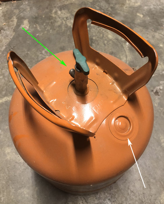
Freon tanks should be evacuated by the disposer. Even having evacuated my own cylinders, I still add a couple of steps to purge potential trace amounts. Open valve (green arrow) and make sure there is no pressure present. Using a center punch or a drill, pop a hole in the blow plug(white arrow) as it's easy to get through. I like to then push compressed air into the hole in the blow plug which will vent out the valve, for a few seconds just to make sure all that is in the can is air. From there, I will angle grind, plasma cut, and weld on the cans without worry. I have been warned that the paint on the cans is not the greatest thing to breath. I generally angle grind with a flap disc and a respirator but I have also thrown hot coals inside the can to cook the paint to make removal easier. These steps are worth doing as some of the byproducts of burning various refrigerants are pretty nasty. Hydrofluoric and hydrochloric acid to name a couple of potentials. I've heard phosgene as a byproduct but I have also read that in unlikely in typical burning type scenarios. The accidental production of phosgene I read about involved cleaning parts with chIorinated brake cleaner and arc welding which if I recall correctly required ozone production. I have seen hvac guys try to "tough through it" and it has had some very bad results. If you open the valve and see liquid coming out or lots of pressure, take it back to the disposer as it was not properly evacuated like it should have been. Some places require the disposer to purposefully put holes in the cans.
-
I'm still around. Just when I thought life was slowing down, it had other plans. Not much to report on the burner front. Four forges in the hands of four smiths. I have not heard a complaint yet. I have spent a bit of time testing the burners in two different forges and the only negative I've got is that they are quite loud after you have listened to them a while. I think it is time I start working on a NARB. I continue to work on the burners in my mind. I'm not sure if it is progress or madness.
-
Same story here. Harbor freight black digital set, less than $10. They are metal though. Within a thousandth of the dial Staretts. I own a few sets for doing things I wouldn't think of doing with the others.
-
Is this what you mean? Page 96 of burners 101.
-
This is the right place to talk about burners. We can't really answer your questions as the picture you have posted shows us only the fuel connection portion. I do not see a burner. I second ThomasPowers advice to go with a known to work burner plan. (Frosty T, Mikey, Reil burner etc.) Built to the plan. Burners look simple but have complexities which make their dimensions critical. Unfortunately, there are a lot of YouTube videos with burners which are bad examples. It's easy to make fire come out of a pipe. It's more difficult to make efficient hot fire. Especially if you don't know what it looks like. Known plans make success much more likely.
-
Just to put it out there, you can link directly to a post. https://www.iforgeiron.com/topic/46536-burners-101/page/13/?tab=comments#comment-528496