MotoMike
-
Posts
554 -
Joined
-
Last visited
Content Type
Profiles
Forums
Articles
Gallery
Downloads
Events
Everything posted by MotoMike
-
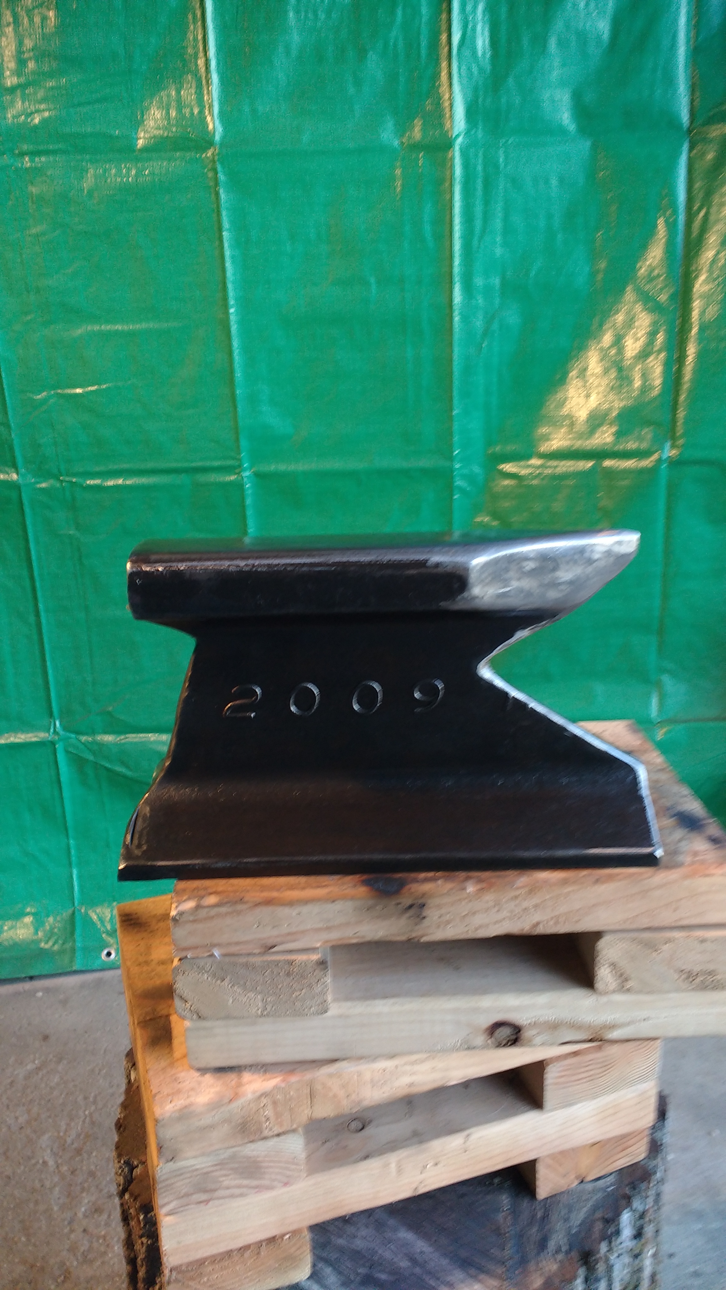
@Charles R. Stevens Not sure if you are refereing to Tock's or Mine. I was conscious of the heel hanging out there and in fact the web does go to the edge of the heal, sort of a corbel and not fully cut away under the heal. I tried to minimize how much web I took away there and on the horn too. You'd asked about markings, the only thing on this small section was 2009 visible on the side and possibly hot rolled in? The scrap pile it was in was all rail road related, but of course that doesn't mean anything in a scrap yard.
-
the thought about crane rail got me curious. Man, there is fodder for some real research there. I think it is possible that it is rail road type rail. Seems less than 100 pound rail is not common any more, and the sizes increase in 10 pound increments instead of 5 pound as they once did. but looking at common North American rail sizes on wiki, I see they don't really follow it. In the old days the total weight of the rail had certain percentages going to the head, web and foot no matter the weight per yard. Now in the bigger rails they've allowed the head to have a smaller percentage which changes the profile. I think those old time prescribed percentage allotment cause rail to look a certain way to me. And that when it didn't, it caught my eye. Mine could be some of the more modern heavy rail used for fast main line rail systems. I see it has 2009 on the web. I see too that carbon and manganese content is specified by weight if I understand correctly since the 60s, so in theory, if you knew the weight per yard of your rail, you could know what the carbon/manganese content was. In N.A. anyway.
-
It blew in on a NorEaster!! @Charles R. Stevens I saw your anvil thread. Looks good. How will you mount it? @Tock Looks like more than I bit off. Good looking.
-

good for a hot cut hardy?
MotoMike replied to MotoMike's topic in Hot Cuts, Anvil devils, metal cutting on the anvil.
thanks wulf -
good for a hot cut hardy?
MotoMike replied to MotoMike's topic in Hot Cuts, Anvil devils, metal cutting on the anvil.
Well Thomas, I gave it a try by myself with a 4 pound engineers hammer and a pair of tongs that really didn't fit. Not productive. just got the hints of flats on the bar. Welded a handle on it and found it much better but too little progress with the four pounder and having learned from an all day session on that drift I made, decided to wait as this steel in a bit bigger than the steel for my drift. Son in law came over and did his first ever striking session. He is a weight lifter and is mechanically inclined and was able to hit the mark well with the 8 pound sledge. but he noted that it was hard work and that he thought he'd make easier work of it than he did. So at this point, I've got a nice square taper about 2 inches long that drops into the hardy. now that I have a shank that my tongs will fit, I will proceed with the rest of it on my own. -
All Right Charles. I'll take a good excuse any day. Heck, I've often gone with a poor excuse as it is better than no excuse. I am not sure what that rail is, it is too big for the rail plates I have and seems taller, a more heavy gauge than other sections I've seen. Times have changed. I live in a rail road town and when I was a kid you could stroll around and pick up rail road scrap at your leisure. rail, spikes clips plate, car parts springs pins and such. Now it is all buttoned down pretty good. free and easy when I didn't want it, under wraps when I do.
-
Thanks Frosty and Judson
-
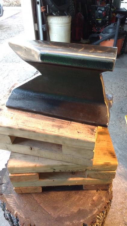
burned up 6 cut off discs and turned a piece of rail into a small anvil. mounted it on a stump about the right height for my grandsons.

-
Show me your Bottle Openers!
MotoMike replied to Arbalist's topic in Blacksmithing, General Discussion
I'm getting a little better at it. I put my touchmark in this one
-
Looks like a lot of work. Hope it works well.
-
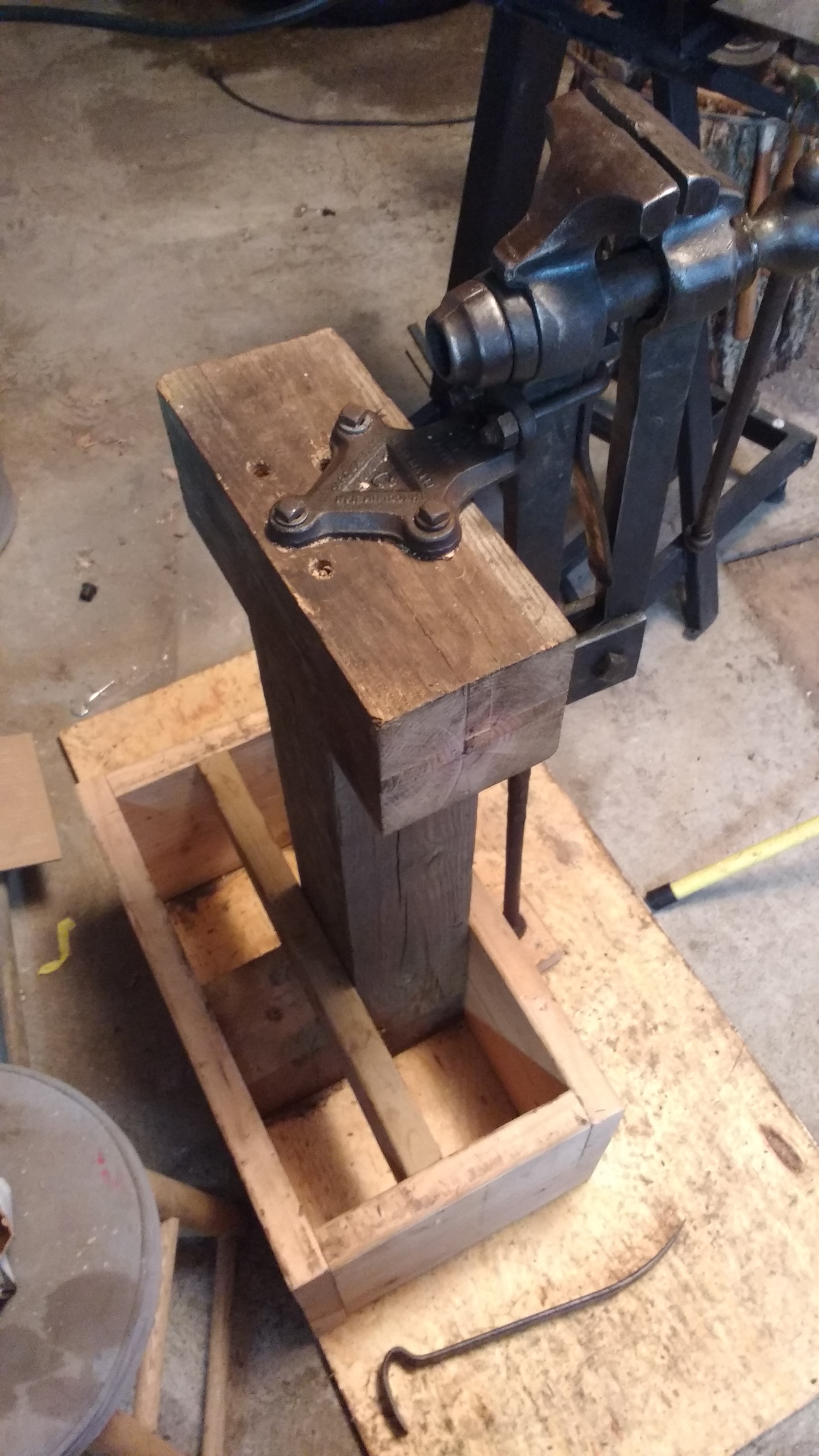
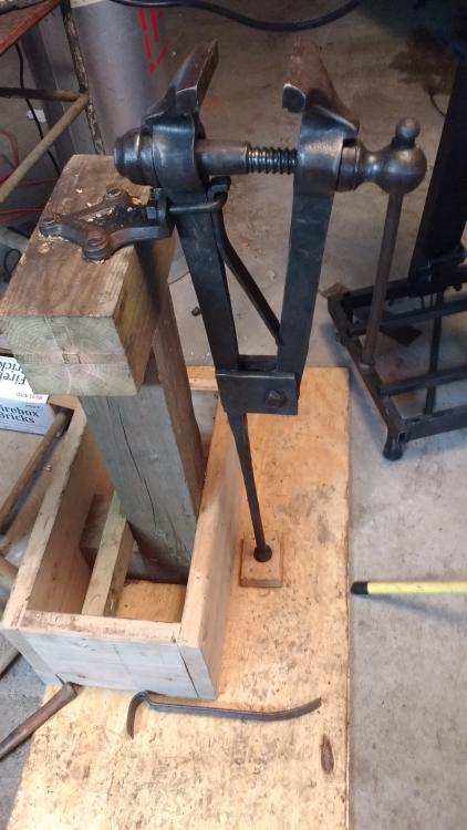
MC Hammer - Thanks. I got lucky with this vise. its screw and box are pretty fresh looking. the handle was bent but I persuaded it back into straightishness. Used it tonight and it is quite a pleasure to use compared to the little bench vise I have been using. quite pleased so far.
-
that is quite helpful Jim. also I think it was Thomas who suggested having a had full of known steels to compare with mystery steel to determine what it is. thanks much.
-
Shawn, Welcome aboard. great to see you over here. there are many guys here who know their stuff and are anxious to share. searching features a bit dodgy, I've taken to using google to search tis site at the suggestion of a couple members. also when you are looking at a thread and want to go to a different page, it won't load and you have to hit the refresh button. good luck Mike
-
Made a forge and a burner but it’s not getting enough oxygen what do I do
MotoMike replied to Tock's topic in Gas Forges
Tock, that is going to be a great forge once you get it sorted. I like the construction and your door set up. see you have it shown with the burner at 12 o'clock and at about 10 oclock. On my next one I will put it off to the 10 o'clock or so spot. I've had a few times when there was not enough breeze blowing through the garage that the plume of exhaust got taken back in through the burner intake. caused it to cut out and had me perplexed till Frosty set me straight. If off to the side, it would be less likely to ingest the exhaust. -
Making hardie tools
MotoMike replied to bigb's topic in Hot Cuts, Anvil devils, metal cutting on the anvil.
@Jim Coke I really like the idea of those wedged secured hardies, thee clamp last shown in particular -
thanks Jim. Grist for the mill.
-
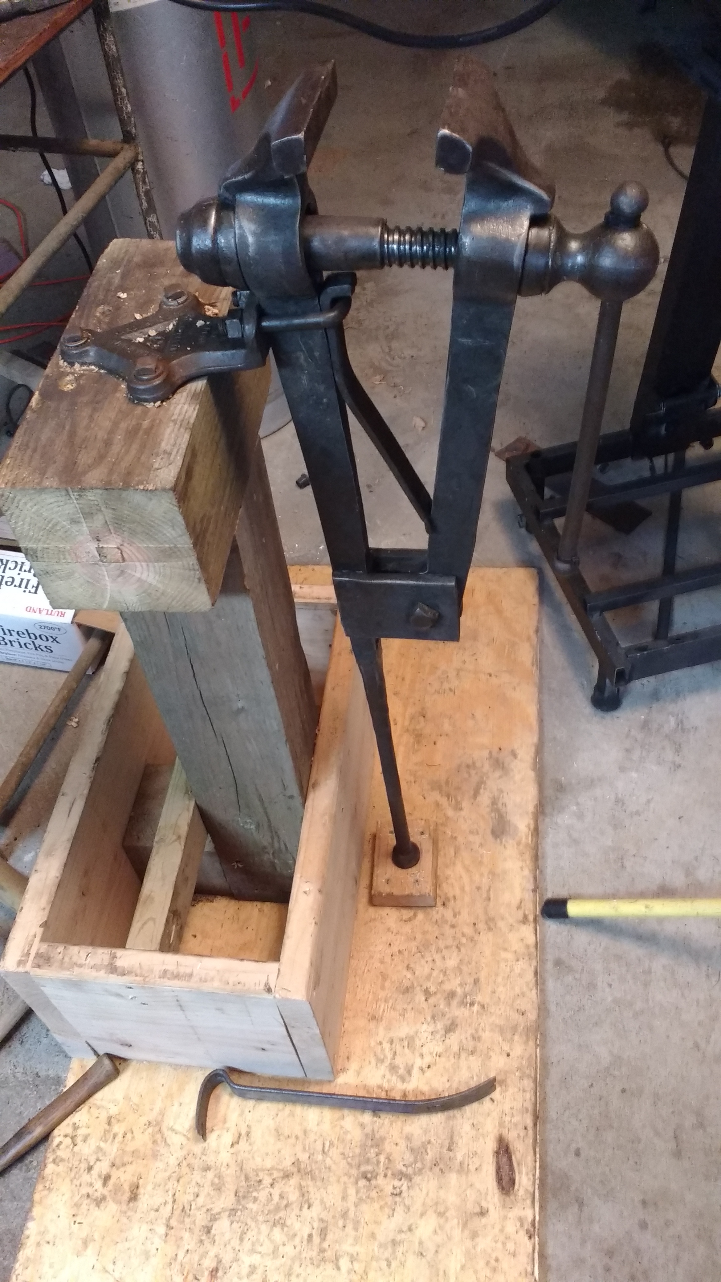
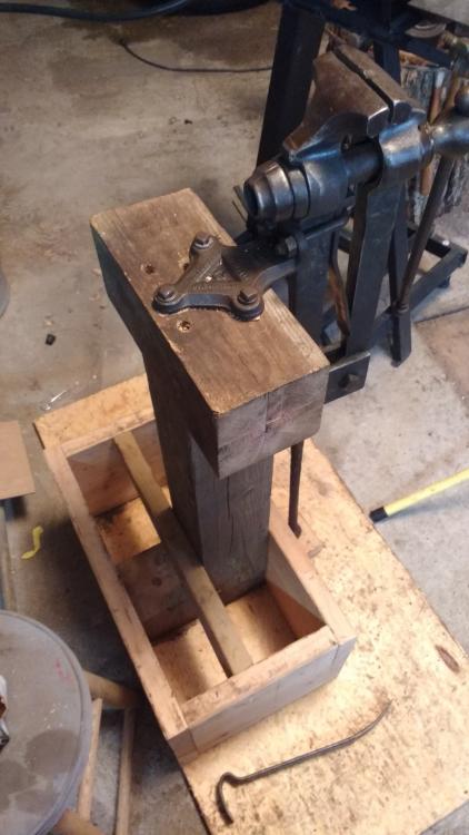
disassembled, cleaned, inspected and lubricated the vise. I was amazed at how smooth and easy it operates once the old dried grease and dirt were removed and replaced with fresh grease. I thought I'd like it to look better if I did not take it down to bright metal, so just wire brushed it and then oiled the whole thing. wanting a portable mount I built this set up hoping it was rigid enough that I could fill it with sand to give it some heft. if not, there is always quick crete. but I'd like to be able to empty it to make future moving easier. the box approaches 2 cubic feet, so filled with sand the whole rig will be over 200 pounds.
-
I think you are probably right. if doing the mig tip, you can change them out to different sized. and by mounting it by the straps you'll not be too much farther in than the Bordeaux modification. I've not done the mig tip modification because it works ok as it. I think the channel in the longer tube of the mig tip is where the improvement occurs. If by u bolts you mean the devices holding the jet tube to the top of the reducer in the original design, I know them as pipe straps. they would be pretty easy to home brew I think. All that said, I bet if you used your mount, the plan size reducer, tube and flare, it would work as is with little trouble. Remember, I only know enough to be dangerous
-
Copesy, I didn't mean to say I knew the exact measurement for the placement of the jet, but that if you do the Bordeaux modification you drill the mounting hole just inside the thick rim of the big end of the reducer. presumably as close fitting to the 1/8 inch nipple you use for the jet pipe, so it dictates where the jet will sit. since this is seen as an improvement, over the original which strapped it to the exterior, there is enough free space around the jet pipe to allow air. I think many who use the 3/4 mixing tube and a 3/4 to 1.5 reducer as the intake, have a means of choking the intake are to tune the burner. The Reil burner is tried and true. most of the articles I've read on it show it working very well just as shown in the above drawing. I note that you mention the jet pipe as 1/4 inch. It was complex for me using inches my whole life, so it is an additional complication for someone in the metric world. This because they are not the size they are named. attached is a chart. So the outside dimension of a NPT 1/8 inch nipple is actually .4 inches. I dare say that despite its size designation, the ID also is not 1/8 inch. I don't know why. I guess in your design, I struggle to see enough similarity to the Reil burner that I would identify it as such without you telling me.
-
ОРЁЛ ( НЕРЖАВЕЮЩАЯ СТАЛЬ), Eagle Stainless Steel
MotoMike replied to ZVEREVSV1's topic in Metal Sculpture & Carvings
I can't imagine. so beautiful that commission should be a big one. my translator says " Eagle Stainless Steel" -
that constricting reducer on the business end looks like trouble brewing to me. would have to restrict velocity and cause back pressure. If I were guessing. The jig is very interesting, but in the reil burner you know exactly where the jet is in the bore. the jig looks as if it would be great for developing a burner. to qualify my comments note that I'm pretty new to all this myself. I've seen a lot of burners that work fine with the threads retained on the inside of the reducers.
-
good for a hot cut hardy?
MotoMike replied to MotoMike's topic in Hot Cuts, Anvil devils, metal cutting on the anvil.
Sounds like you know me and the son in law. -
good for a hot cut hardy?
MotoMike replied to MotoMike's topic in Hot Cuts, Anvil devils, metal cutting on the anvil.
Thomas, you are a mind reader. I've a stocky son in law who is a handy lad around things mechanical. He might be the striker! -
good for a hot cut hardy?
MotoMike replied to MotoMike's topic in Hot Cuts, Anvil devils, metal cutting on the anvil.
Thanks fellas . since I have it all $2.40 cents worth, I'll probably give it a go and just see how it goes. sort of wish I'd found something just biger than my hardy instead of half an inch bigger. -
good for a hot cut hardy?
MotoMike replied to MotoMike's topic in Hot Cuts, Anvil devils, metal cutting on the anvil.
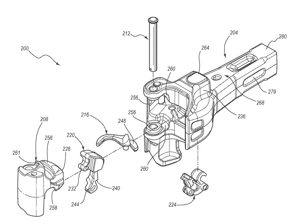
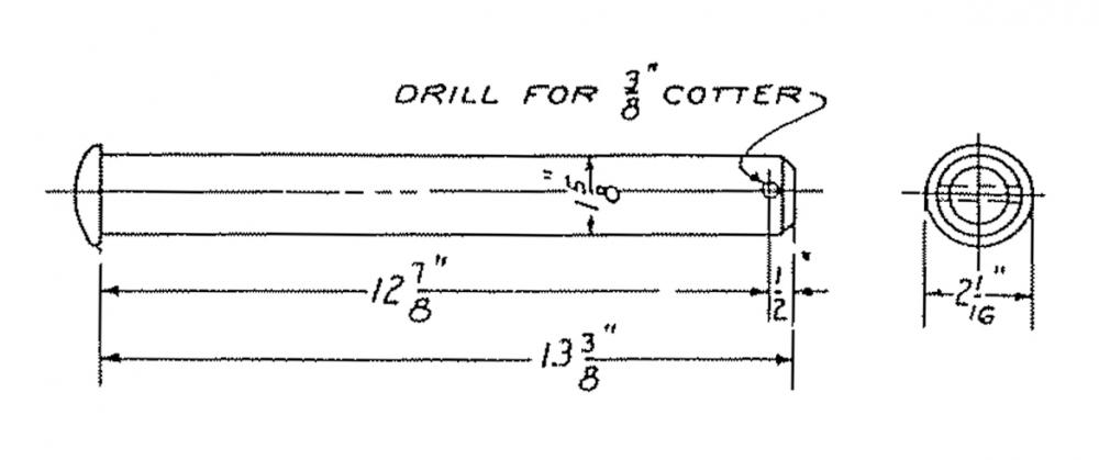
Ha the interweb. I think this is the part. sounds like you were exactly right Thomas. Part 212. National Trackwork, a DBE and ISO 9001:2000 certified manufacturer in Itasca, Ill. supplies quality freight car and locomotive fasteners and pins such as C10 Knuckle Pin. They are made from AISI C1060 or equal steel, tensile strength (ksi) 135, yield strength (ksi) 75.2, elongation (%) 18.5, reduction in area (%) 44.8, and machined to RMS 125 straight within 0.050-inch.