
Mike BR
Members
-
Joined
-
Last visited
Everything posted by Mike BR
-
Another "trick" I've picked up is to use fine threads whenever you have the choice. There's less material to remove (so less force on the tap), and tap itself is stronger. (But coarse threads are usually better for non-ferrous and other soft materials, and if you're matching an existing fastener, of course.)
-
Let's see: If I were more observant, and my wife still bothered with Chinese new year, and we moved to Russia . . .
-
Not to mention that the October Revolution happened in November.
-
I took a look at the manual. There are various torque and stall protections settings you could try tweaking, around F 118 to F 124. The overvoltage error is a little odd -- based on the not-very-clear description in the manual, it protects the VFD from excessive voltage the motor may generate the VFD slows it down and it acts as a generator. I guess one possibility is that the torque protection is kicking in and slowing the motor, which in turn causes an overvoltage. The first thing I might try is bumping up the rated motor current (F 140) an amp or two. That might stop the torque protection from kicking in in the first place. Don't go hog wild, though. . . If that doesn't work you could perhaps try setting F 123 to either 0 or 2. That looks like it would let the motor continue to operate after an overtorque is detected. (I can't tell from the poorly translated manual what the difference is between 0 and 2.) And one final thought that I should have put first -- if you haven't already, check that the wiring connections are tight. I don't have anything specific to base this on, but it seems like a loose connection might cause the VFD to do strange things.
-
It’s a good idea to grind off any heavy burrs; you can end up with minor cold shuts otherwise.
-
I could be all wet here, but I'm imagining a crank driving a piston rod that pushes a piston. If so, the geometry would mean that the rod puts a significant side force on the piston during the compression stroke. And the direction of that side force would depend on the crank rotation. If there were a port on one side of the cylinder, for example, you'd probably want the rod pushing the piston toward the opposite side.
-
If it's three phase, it could easily be hooked up "backwards."
-
If the piece does warp in the anneal, it shouldn’t be too hard to straighten (see what I did there?)
-
I have a piece about maybe 1" X 4" X 6" that I use. But I stick to some pretty basic alloys, and generally anneal by leaving the piece in my gas forge, shutting it down, and blocking the vents. I put small pieces on the castable floor of the forge, with the hot chunk of steel on top.
-
A simple trick is to put the piece you're annealing on a thick chunk of steel heated to the same temperature, and put the whole mess in the annealing medium. The large mass greatly increases the amount heat that must escape to reduce the temperature by a given amount. If you have a piece of thick-wall tubing, that should work even better.
-
This may not matter in the end, but I'm a little skeptical about the "self tightening" concept. It seems like the object should be to keep the punch from forcing the tongs open, not necessarily to wedge it into the jaws as tightly as possible. What seems important here (maybe) is that when the punch wants to twist in the jaws, it's trying to push the inside jaw directly back into the pivot (which it obviously can't do), rather than pushing the bits apart as it would in conventional tongs. That seems to me like the aspect of the geometry we should focus on.
-
One other thought, though this may have become obvious when you adjusted the tongs: In the current configuration, the inner jaw moves almost parallel to the outer jaw when it closes on the punch. This gives a high mechanical advantage and a very tight grip, but it also makes the rein position very sensitive to punch thickness. If these were set up like conventional tongs, with the concave jaw and the cam facing each other above the pivot, the two bits would move directly toward each other and there would be a lot less mechanical advantage. Of course, apart from weakening the grip, that would mean that the punch was aligned with the reins, making the tongs useless for their intended purpose. But you could try something in between, for example by moving the business end of the concave bit a little closer to the joint and adjusting the angle so the punch was perhaps 70 degrees to the reins instead of 90 degrees. That would reduce the mechanical advantage some and make the grip somewhat weaker. But it should also permit the tongs to reasonably hold a wider range of punches. You could put bends in the reins themselves (i.e. on the side of the joint closer to where you hold the tongs) to bring them back to 90 degrees. Of course, the trade-off between grip and versatility might or might not be worth it.
-
Yep — that’s it.
-
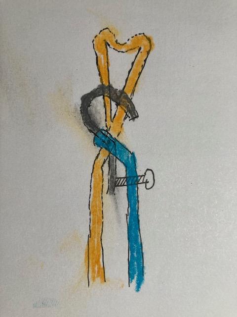
I think the answer is "no, I can't," but you can "draw" your own conclusion. The outside jaw/rein is orange, the inside jaw and "stub rein" are dark gray, and the "split rein" is blue. In addition to the leg you see, the split rein would have another blue leg on the back of the joint, with the split ending somewhere between the joint and the bend (as drawn). The other version I suggested would have the gray stub rein running inside the split (which would extend further down the blue rein). The end of the gray stub would emerge on the right to pass under the head of the screw. And I haven't quite decided, but I might go with a right-hand screw
-
Those are so neat it makes me want to make a whole set. Maybe when I retire. . . Meanwhile, I have a (relatively) simple idea for an adjustable rein, if anyone's interested. Cut off the rein for the inside jaw, leaving a stub a couple of inches long. Make a new rein, split so it will straddle the existing joint; drill it for a longer rivet. Offset the new rein so it will sit outside the stub rein, and drill and tap it for an adjusting screw that will bear on the stub rein near the end. A variation would be to make the split nearly as long as the stub rein, and thread the stub rein through so it ends in a flat section that extends a little below the crutch on the outside of the split. Then set up the adjusting screw so the head pulls the stub rein in toward the split one.
-
Maybe someone here has experience running equipment like that on VFDs, but it looks like 10HP units are now available for a few hundred dollars. 10 HP is already quite a power draw on 220V single phase (if that's what you have), and you have to add the rotary converter motor on top of that. A VFD should require less total current, and might save you on wiring.
-
A couple of thoughts on this. First, if you want to calculate the amount of material required, you can use the formula for the volume of a four-sided pyramid: L X W X H / 3. If you continued your taper to a point, it would be 60" long. 1/2 X 1/2 X 60 / 3 gives 5 sq inches. The part you aren't making is 1/4" at the base and 30" long, which gives .625 square inches. Subtracting gives you 4.375 square inches, or 17.5" of 1/2" square. Of course, that doesn't account for scale losses or for rounding up, so you need to allow a little windage. To forge it out, I'd probably start by drawing steps. First, I'd mark off the stock you need for the taper, maybe 18" or 19". Then I'd make Billy's fuller at the mark at what will be the small end of the taper, and also make his short taper to avoid any possible cold shuts. Now, your final taper will get 1/16" narrower every 7-1/2". I'd make four stepped sections each maybe 7" long -- the idea it to allow some for the growth when you make the final taper, but also leave a little extra stock to work with. Starting from the big end, I'd mark off a 7" section to leave at 1/2" square, then draw out the rest of the piece (except the leaf, of course) to 7/16. I'd then mark a point 14" from the big end and draw the remainder to 3/8, then 21" and 5/16. Your 5/16 section probably will come out short, so borrow a little from the 3/8 section, and adjust the other two sections accordingly. At that point, you'll have the metal largely in the right place, and you can forge the final taper by eye. (Mathematically, the thinner sections will grow a little more percentage-wise when you make the final taper, so you could start with a 7" section at the big end, then maybe 6-3/4", 6-1/2", and so on. But ultimately you're forging and judging by eye anyway.)
-
I second what swedefiddle said. And the few times I've had contact with one of the Swedish hometown associations, folks have been bubbling over with information and eager to share it. On the other hand, I think they're generally small volunteer organizations run mostly by retirees, so it's not too hard to see how something could fall through the cracks. It looks like the Ludvika association has some information on Lindesnäs, so it might be worth trying https://www.hembygd.se/ludvika/contact. visitdalarna.se might be a possibility as well. Finally, Lindesnäs isn't an Eco Museum site, but perhaps someone at https://ekomuseum.se/en/ could give you a lead (and anyway, there's a lot of interesting information on the website).
-
One other thought: Stora Kopperberg bought Söderfors in 1907. Conceivably they could have put the Lindesnäs mark on a line of anvils produced at Söderfors (whether or not Lindesnäs had produced anvils before it was shuttered).
-
Anvil production would have been a pretty big operation, and it looks like Lindesnäs was owned by Stora Koppergerg corporation by the time it was closed and the operations relocated. So if Lindesnäs was in fact making anvils with that mark, it's very likely that the corporation would have kept using it after production was shifted to Borlänge. (Also, the iron and steel industry was still going strong in Sweden at the end of the 19th Century, and indeed it still is. Emigration is of course a major theme in Swedish history, but I doubt a lot of skilled ironworkers would have left.)
-
It can be very hard to bend things flat. Sometimes there are trapped stresses that make one part pop up (or down) as soon as you get another straight. If Frosty's technique doesn't work for you, you might look at removing a little wood so that the low parts of the copper rim can extend down into narrow grooves in the walnut. But only if it would work aesthetically, of course.
-
Since there’s enough angst in the world already, perhaps we can choose to believe that the anvil was irretrievably damaged prior to the deliberate modification.
-
In this context, "carbon steel" generally means steel where carbon is the major alloying element (i.e. not stainless steel). It doesn't necessarily refer to high carbon steel. Based on a quick search, thermal conductivity decreases somewhat as carbon content increases. So I'd say the lower the carbon the better.
-
In theory, you could fit a smaller drive pulley, or add a V-belt pulley and drive the whole shebang with an external motor. But either could be as challenging as building a new grinder, and (as others have pointed out) you'd be solving the wrong problem anyway.
-
Premium unleaded tends to have more volitile compounds, so it’s even worse. (I guess that might make it a better solvent, though. . . )