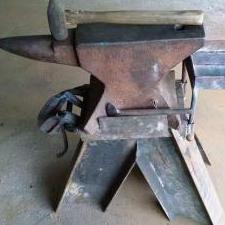
August 7, 20223 yr I have a couple of issues with my new-to-me fly press on which I’d appreciate some advice. The first is that the depth stop is missing. Unlike some older presses and the modern Indian presses where the main screw itself is threaded to take a stop that comes to rest on the top of the frame (as on Anachronist59’s press in THIS COMMENT), mine has a threaded piece attached to the frame, that appears to take a threaded collar of some sort that limits the screw's downward travel. (ADDENDUM: the threaded piece atop the frame appears to be 2-1/4" dia. x 10 tpi x 2-1/2" tall.) I suspect that the stop was originally a very heavy split nut locked in position with a pair of bolts of some variety, one on either side of the main screw. I’m also guessing that the two halves were removed at some point and later lost. There is no easy way to remove the screw (at least, I haven’t figured it out yet), so unless the stop broke off and was never replaced, the two-removable-halves theory seems to me like a more realistic scenario. Any thoughts about how I might go about replacing such a stop? I’ve got a couple of crazy ideas myself*, but I’m open to more realistic ones. The second problem is with changing the position of the handle. I’ve seen a couple of different arrangements for this on other presses, including one where one loosens a setscrew, removes a pin (which normally acts as a key to keep the arm from rotating on the screw), rotates the arm to the proper position, drops the pin back in, and tightens the setscrew. Mine is most like that, at least insofar as it is clearly designed to be positionable at six different angles around the screw: However, not only is the pin a super-tight fit in the arm (slightly less in the screw), the top of the screw and the corresponding bore in the arm are actually tapered by a good 1/16”. This means that in order to remove the arm, you have to remove the weights first, tap sharply on the underside of the arm, lift it off, rotate it to the desired position, drop it back down, and out the weights back on. It seems to me that the simplest solution here would be to make a spacer (about 15/32”) that would keep the arm from dropping down far enough to lock in place; this would fill the space between the underside of the arm and the top of the solid collar at the top of the screw. I'd then make a replacement pin (incrementally thinner than the existing one, but longer so that it can be grabbed onto for easy removal and replacement), and perhaps drill and tap the arm for a setscrew to lock the pin in place. Any thoughts? * And one a bit less-crazy: a series of stackable spacers, with a central hole large enough to fit over the threaded piece on the frame, but with a piece cut out that’s big enough to clear the straight section of the screw shaft.
August 8, 20223 yr Author 23 hours ago, JHCC said: make a spacer Found an eye bolt whose opening is just a hair too small and whose thickness is just a hair too fat. A little die grinder work, and it should be perfect. 23 hours ago, JHCC said: a replacement pin I have some square stock that would work for this, but a question: does such a key need to be hardened? My existing square bar is A36 or the like, but I could certainly forge or grind some 5160, 4140, or O1 to shape. Thoughts?
August 8, 20223 yr Author Update: a half-round file for the inside and a belt grinder for the flats, but all appears well. The fit between the shaft and the arm has the tiniest bit of movement but is otherwise quite snug. The key fits tightly in the keyway in the arm, but moves easily in those cut in the shaft. Lifting and rotating the arm is reasonably easy (especially if I take the weights off first), but a removable key would be easier still.
August 8, 20223 yr My pin appears to be mild steel, but I haven't spark tested it. I can certainly see the logic for making out of at least 4140 or the like, but I don't know that I would harden it. Some day you might have to drill it out... If nothing else it is good to have the pin project up out of the locator slot at least an inch or so. This will allow use of a vice grip to help pull it out. Actually my pin is cylindrical, rather than "D" shaped, so it can be rotated to help free it if jammed.
August 8, 20223 yr If I were forging my own, I might be tempted to forge it like a tennon with a larger diameter top that protruded above the socket. That way you could slide a purpose made claw tool under it to lift the pin if it ever got jammed. Kind of hard to describe, but easy to sketch if you need.
August 8, 20223 yr Author I was thinking of a finger loop. Actually, now that I think of it, I wonder if any of the other ring bolts in my supply are big enough to grind down to the proper size.
August 8, 20223 yr Author Update: an interesting possibility. Thick enough to grind down to the desired size and shape, easy to grab barehanded, and if it gets stuck, a bar through the eye would give plenty of leverage to muscle it out.
August 9, 20223 yr Author Re: the missing stop block. An old college friend who coaches a robotics team is sounding out his students to see if any of them wants some practice threading on the lathe, and we’ll probably do a 3D printed prototype to make sure it fits properly. I guess this means that I’ll have to figure out how to remove the screw.
August 9, 20223 yr If you don’t want to remove the screw, cut the nut in half and set it up as a clamp on nut. Should work just as good as a jam nut when tightened, and would be easy to loosen and spin to the next position. Keep it fun, David
August 9, 20223 yr Author The bolt ground down to a properly sized D-shaped cross section: Which, by some pure miracle, worked perfectly the first time.
August 9, 20223 yr Author Still haven’t figured out how to remove the screw. However, THIS POST and THIS ONE present some interesting possibilities.
August 10, 20223 yr Author On closer examination (and with a few judicious squirts of WD-40), I find some holes to take a pin spanner. No need to disassemble just yet, but at least I now know how.
February 26, 20242 yr Author Revisiting a long-dormant post, and returning to the question of the depth stop. As noted above, a friend and I have explored (without success) doing a 3D printed version of a depth stop, which could then be machined in steel. With that more or less permanently on the shelf, I've been relying on blocking the workpieces up to the proper height relative to the tool, which is awkward at best (especially since the blocking needs to be clamped down). However, I just found the following interesting possibility on eBay: a lathe faceplate that's threaded to 2-1/4" x 10 tpi. I thinking this might do reasonably well, with some height extensions welded or bolted on and with a slit cut in to make it compressible with a locking bolt. Thoughts?
February 26, 20242 yr The stop block on my fly press has left-hand threads. If I’m not imagining things, I see them in one of your pictures as well. In any event, I suggest checking before you order the faceplate. If the threads do match, you might need to cut away the “plate” part of the faceplate to get the nut part flexible enough to clamp down evenly.
February 28, 20242 yr Author Well, the press does have left-hand threads, and the faceplate sold before the seller got back to me about whether it was RH or LH. Ah, well.
February 28, 20242 yr Pretty sure that lathe faceplates would all be RH threads. LH would lead to unwelcome excitement I would think! --Larry
February 28, 20242 yr Looking at the bright side, if it did have LH threads, there's a good chance it will be for sale again soon.
February 29, 20242 yr Author Unless that's what the buyer wanted, of course! In other news, I texted my friend to let him know that we're dealing with LH threads. His team is gearing up for a competition, but he'll get one of them to make another prototype after that's done.
November 24, 2025Nov 24 I know this is a several year late reply, but your press appears similar to mine, which has the original depth stop collar. I'm attaching a few pictures in the event it is helpful to you or someone else.
Join the conversation
You can post now and register later. If you have an account, sign in now to post with your account.