Mikey98118
Members
-
Joined
-
Last visited
Everything posted by Mikey98118
-
dgr, I had a look, but did not find any e-cowlboy forge photos of their gas pipe and MIG tip. So, all I have to go on is my own previous experience; that tells me that copper pipe is quite unlikely to be used as a gas tube. A brass gas tube is far more likely. Old brass parts sometimes look like copper in photos. As to how they get a MIG tip with 1/4-27 thread to screw into a 1/4" outside diameter tube or pipe, the gas tube is probably 5/16" outside diameter by 3/16" inside diameter. Although, MK brand MIG tips have smaller diameter thread, which would probably just barely work in a 1/4" gas tube; hey are a superior tip, but I quite using them, because they are just too hard for people to find. By the way, their photos show a lemon yellow incandescent interior, which is consistent with 2000 to 2100 F heat range. 2700 F interiors are white hot. But the worst thing I see about these forges are the exhaust openings and doors. They look nearly guaranteed to warp from the heat of exhaust gasses. I could go on picking out things I don't like about this forge...but, enough said. "Last thing for Mike's new book. I've seen it mentioned in your writing that mufflers are zinc coated. I installed a few mufflers in my younger days and never saw the telltale yellow soot of zinc when welding them. I believe non-stainless modern exhaust components are aluminized and not zinc coated steel." Ups! Suppose I'm showing my age Thanks for the update.
-
Nice one, Lee. Tell us a little bit about the bird houses. I for one, am interested. We have a garden, a bird bath, loads of birds, and three trees to place them in; but no bird houses.
-
Good one, Trevor; I like that Yes, we just never seem to be satisfied...I have had some of the same problems. We must do a better job of coaxing?
-
I have noticed a recent uptick in activity on this thread, but fail to see a corresponding increase in questions. Your worries aren't state secrets, or even surprising to us. So you might as well fess up, and get some answers. We all promise to be kind; really we do
-
-
Frosty has it right. Two one inch layers crinkle far less than a single two inch layer. Once rigidized, both layers are glued back together again. So, you gain a lot of control, when installing the insulation, with no down side. What's not to love?
-
It must be added that what castable refractory you choose will effect the values mentioned above. Castable insulating refractory will work far better, with less fuel, than castable refractory used in glass furnaces, for instance. Also, heat reflective finish coatings are just as important as type of refractory used.
-
Relax, Scott. We are all still smiling
-
Tools only matter to me in what they can or can't help the artist to accomplish. By artist I include everyone from art student to would-be hobbyist, to craftsman. For the only differences between them are the decisions they make; beginning with "will I become this or that...or will I not even try." I understand about the tree; a heart attack and two strokes made a lot of changes in my own plans; worse luck, while I was coming back from all of that, I became a rickety old man. It's enough to make you grin at yourself
-
Frosty, So, do you have any thoughts about this tool? I think that if nothing else, its design is a good direction. On the down side, I don't think that I really understand their version of 220V motors and controls.
-
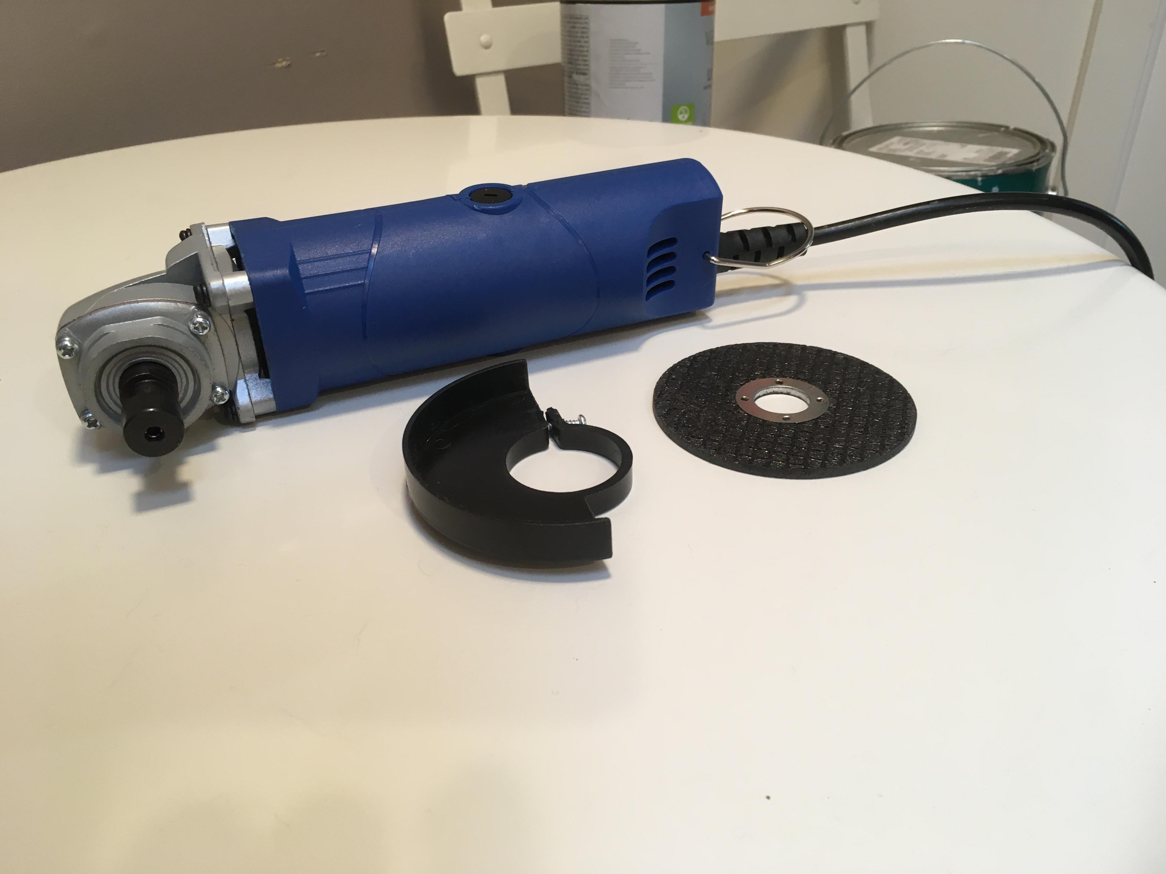
There are at least two different manufactureres of these angle grinders; this is the REISBA model; it is supposed to be variable speed, although mine dies when I try to slow its speed. The RISBA grinder is rated at 250 to 360 watt grinder that is rated to run between 3000 to 14000 RPM. It is meant to plug into 220V outlets, although it will run at half speed from 110V outlets; the run on both 50 and 60 hz. The other model is only rated at 135 watts, so be careful to avoid it.
-
Sorry about the huge photos. We tried to remove the first two, but couldn't. So, we put up a third photo that had been downsized, but it came up full sized too. The moderators are welcome to get rid of all three photos; we could not do anything with them on this site. In the meantime, the cutoff disc in the photos are 3" diameter, which should give folks a fair idea of how small these grinders are. A rotary tool mandrel, which accepts 1/8 shafts, can be mounted in the grinder's hollow spindle, so that this tool, which sells for less money than a good quality rotary tool can be used to cut, grind, and shape burner parts, along with the heating equipment they are mounted in.
-
Coming tomorrow. I will need Kathy's help with the technical stuffupdate: It took some time to find an up/down 110V to 220V transformer I was comfortable with purchasing. Finally found a Japanese model for $110. It arrived today, so I could finally check out the grinder on full power; there was pretty good power for such a small grinder, but the speed control circuit did not work at all. I don't personally mind that, since I plan to run speed control through a separate circuit, but others would probably feel ticked off by that. All in all, am still happy with the purchase.Okay; I definitely advise you to go ahead and use your burner as a torch. Pay no attention to what those other guys saidTo add to what Buzzkill and Frosty told you: (1) You have twice the amount of 3/4" burners needed to turn your forge yellow hot; not orange like you show. (2) The photo seems to indicate heavily oxidizing flames, which is what I would expect from such a small gas orifice in a 3/4" "T" burner. Follow Frosty's advice, so that your burners will produce nuetral flames; then you will be anle to follow Buzzkill's advice; resulting in fuel reduction, along with a whole lot less scale on your partsPerhaps there is a point of confusion. While heating up the inside of the forge with your burner would be the fastest way to melt these little silica particles in place, most of us just pass the burner over the inside in patches. All at once, or area by area; either way will work just fine.External lips greatly interfere with air intake. Probably, an internal lip would not be equally bad, but pretty close to it. Ironically, the threads will not create drag, because they will create a barrier affect, forcing the incoming air to flow away from their tips, will a single ip will do the opposite; it will create a ring of vortices, which inhibits air flow.So, I looked this torch up on Amazon.com, and it is not a bad design. However, its double tube construction will prevent its being protected with a stainless steel outer tube; this means that it will oxidize away pretty fast, if mounted within a forge. Also, its flame tubes are crimped on their ends. Once those ends oxidize away, the torch will not function properly, unless you can again crimp the ends of the remaining tubes.I find these canister torch-heads a fascinating and irritating subject. The irritation comes from ludicrous advertising, and the difficulty in assuring that you get a quality product; especially as higher prices do not assure better quality from drop-shippers!!! For some of us, using dual-fuel torch-heads is pretty much of a rabbit hole, leading straight to Frustation Land. However, adding a propane adapter hose, so that a larger refillable gas cylinder can be used, and a stainless steel tube over the torch-head's own stainless steel flame retention nozzle, to keep its thin stainless steel wall from oxidizing away in short order, can make dual-fuel torch-heads viable and efficient for mounting in heating equipment...so long as the torch-head does not leak. Anyone who successfully runs the gamut of obstacles can end up with a neat little forge burner, with controls thrown in...IF; all others crash and burn. What can you do to improve your odds? Carefully read customer reviews of both product and seller on Amazon.com. If the product only has a hand full of sales, move on. Some drop-shippers, who are selling junk, can and will just keep redoing their offers, to get rid of the tail of bad reviews. Welcome to the wild East, Yankee! Did I mention thick stainless steel enough times to get the message across? Brass torch-heads cannot be efficiently mounted, without melting. Thin stainless steel flame retention nozzles will oxidize away far too quickly, to be economical. Don't think I'm trying to discourage anyone. I continue to play this game, and find it rewarding; just don't think things are "cut and dried," cause they're not.Yes, that is true, but for short periods it can be exceeded. It takes time for a 16 ounce canister to chill down. Just like racing an engine for short periods, to merge in heavy traffic is expected, but continuing to race that engine is a very bad idea. Nevertheless, practicality is completely on your side, for these sellers merely compete like carnival barkers for the sucker's attention. No one is dumb enough to think a barker has their interests in mindYou might want to read the Forges 101 thread for answers on how to mount burners; not the Burners 101 thread, which is devoted to how to build burners. Although Buzzkill and Frosty have given you good answers, already.I don't think the usual drop shippers even bother with that. I think they just cut and paste the handiest description from a similar product. No ""writers" needed.