
Another FrankenBurner
-
Posts
625 -
Joined
-
Last visited
Content Type
Profiles
Forums
Articles
Gallery
Downloads
Events
Everything posted by Another FrankenBurner
-
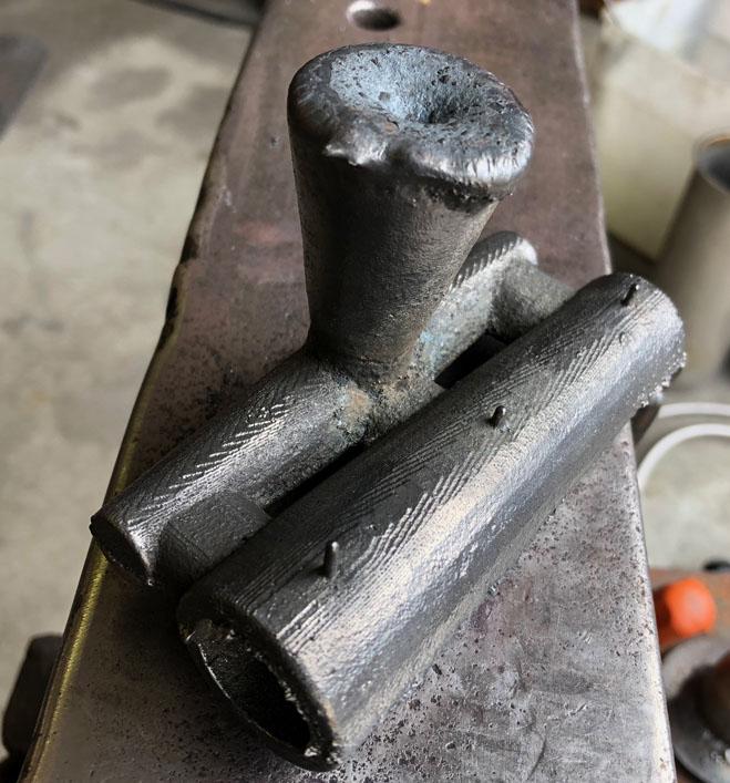
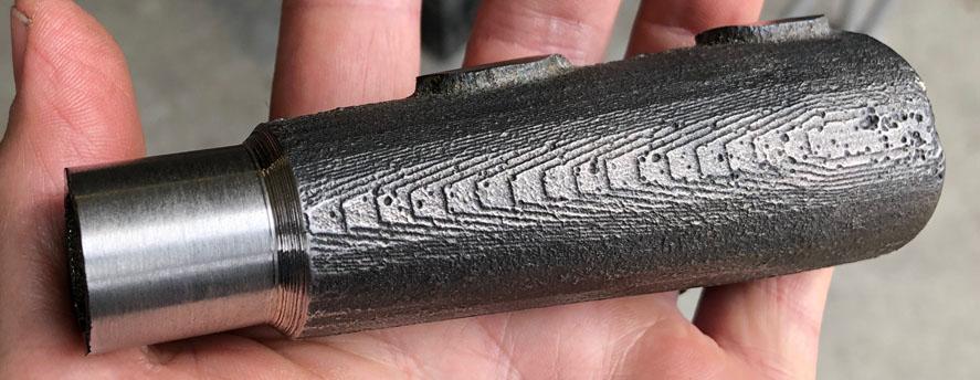
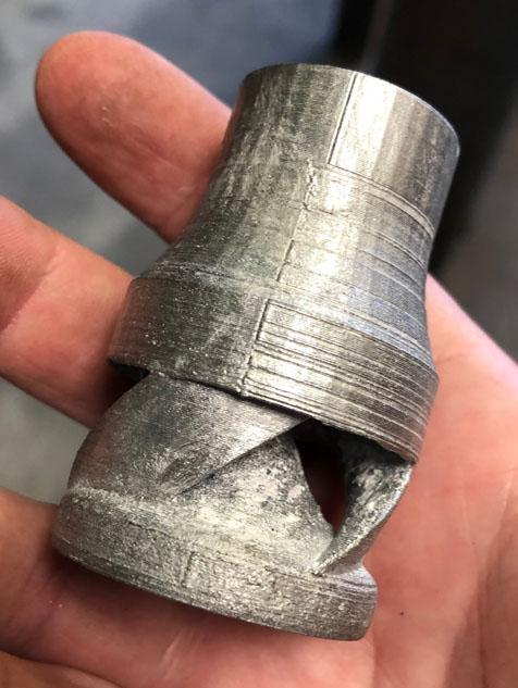
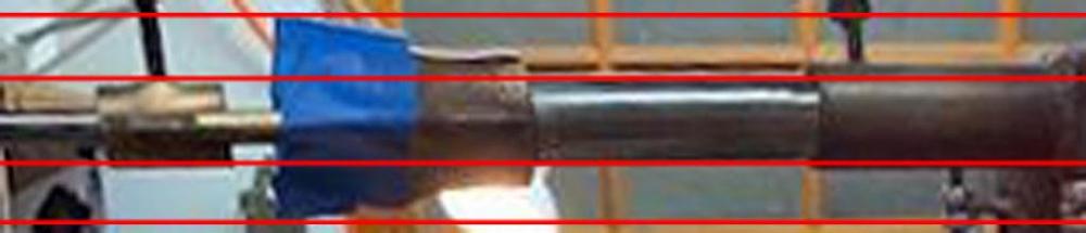
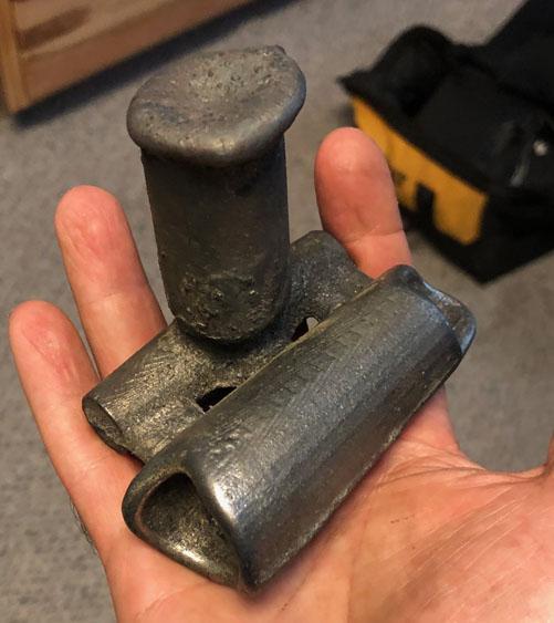
 I stated what I meant quite poorly. I did not mean to imply stronger vortex and more air induction can't be had together. All I meant was the more energy spent on vortex, the less there is available for induction. Energy in = energy out. The wasp waist burner is a great example of using that energy more efficiently. Do you suspect that the reason the wasp waist does so well is because it promotes stronger vortex or simply because of the drop in resistance? Maybe ribbon burners are superior because of their shorter combustion zones? For a single port, I am picturing some kind of fire tube between the burner and the forge. A nozzle extension of sorts. When I first heard the term, I did some googling. I found a bunch of corset styles. At the time I assumed it was where the term came from because of the likeness of shape. WIkipedia Wasp Waist. Those look extremely long compared to most of the commercial wasp waist burners I have seen. Quite neat. I will have to get some pictures of the burners I see quite often. Today was a good day. Our first successful iron cast: The three little nibs are from pinhole air vents. We were not hot enough previously. We up sized burners: The top is one of our first investment casts, the bottom is burner was cast yesterday. It is another experiment. The casting has improved a bit. With more btu's and more patience, the metal was a bit hotter this pour: Here is another shot from the bottom after some machining. It still needs a bit of work.
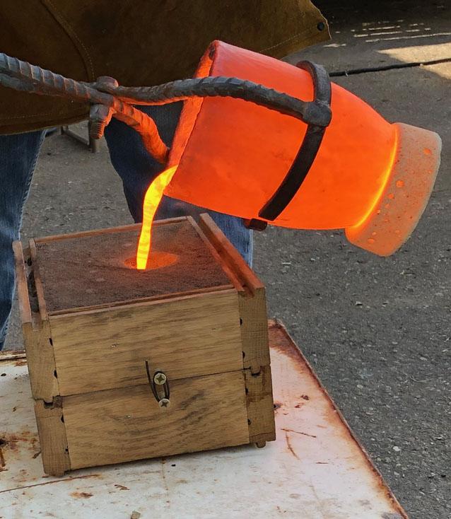
-
Version G1 runs rich with the 023 tip. The flame is a bit unwieldy and dispersed for a hand torch I would think. If the orifice size were better matched, the flame would be smaller and shorter. Maybe useful if wider area lower outputs were needed. Though I wonder how stable the flame would be if we started to lean it out. Welcome aboard Phil. No STL's have been posted. If you are good with CAD, read though some of the pages and you can get a good approximation as a starting point. Here is v73 in aluminum. Still needs the investment cleaned off. He is a 3/8" guy. You can see the misalignment spots from the 3D print in the surface.
-
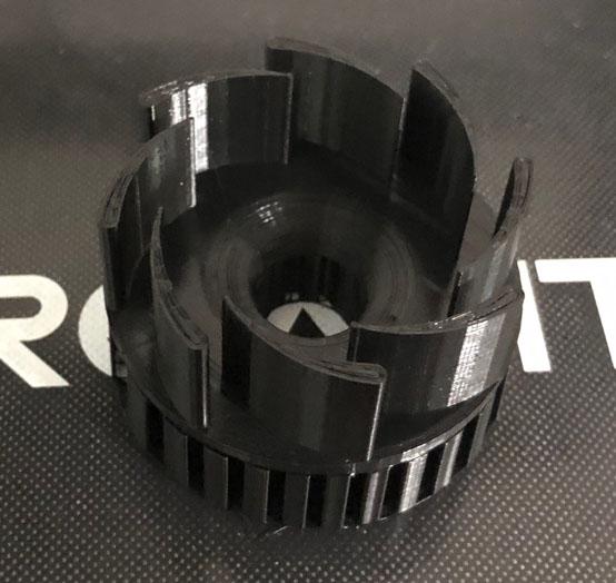
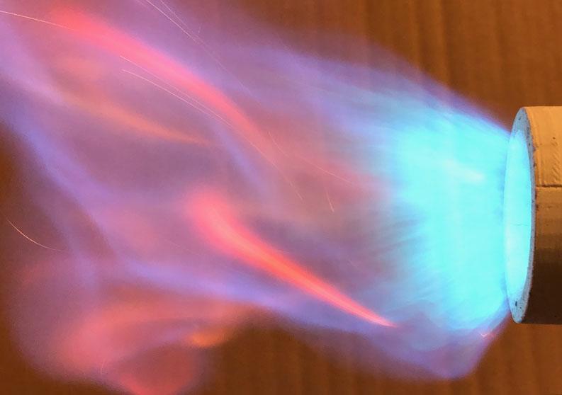
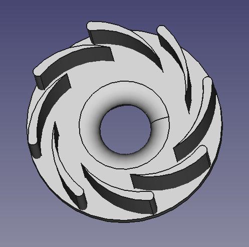
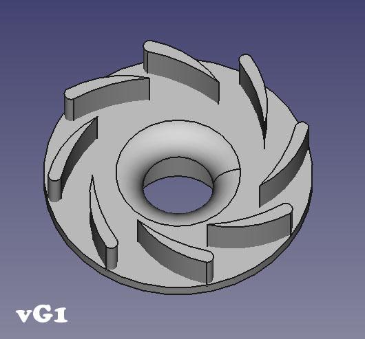
This first version was made to match G-son's mental image. It is a perfect example of the need to encourage not force a vortex. We successfully increased the vortex energy. In doing so, we decreased the entrainment energy. This will always be the case and has a balance point. We want to use as much energy for air entrainment as possible while only using as much as needed for the vortex to do what we want it to do. We can find the most efficient way to give the vortex energy and then find the balance point. We can make the vanes taller and/or decrease the quantity to increase the inlet area which can induce more air but as we increase inlet area, we decrease air velocity. We want this, as any restriction that increases velocity is decreasing total air entrained. The downside is that as the velocity lowers, the momentum decreases which makes it's path much shorter to the low pressure zone. It sounds like we are going to 3 vanes for vG2 and possibly taller vanes for vG3. One thing I can say about this version, the radiant energy felt on my face while standing near this thing is much higher than the versions concentrating the flame forward. It makes me wonder how the vortex flame will act inside a forge.
-
The front half of vG1: It is very cool looking. It's air entrainment is pretty low as expected. More power to the vortex is obvious in the flame. It is a squat wide rotating flame. It is a bit mesmerizing to watch the secondary flame dance about.
-
It's your idea, let's stick with the original first. After that we can try 3 vanes on version G2 if you like. I will have to try Frosty's no vanes idea as well. I am having a hard time picturing this one. I think I follow with the cutting of the cans and offsetting the outside shell. I get lost at the point of adding this to the reducer and how the air enters. All very awesome. From what I can see, it is hard to discern improvements. They all look like serviceable flames. I like the contrasting flames of the Funnel A/New Choke and the 5 fin choke. The Funnel A/New Choke picture shows a flame that is darker blue, straight, longer, and more pointed. It is moving faster and it's secondary flame is straight and more transparent. The five fin choke picture shows a lighter blue flame, which is shorter, more cylindrical/blunt, and a secondary which is larger, fluffy and has rotation. The flame is moving slower. The nozzle is hotter in the vortex flame burner picture, which may be responsible for what looks like more secondary flame. I have seen the secondary flame go from invisible to highly apparent once the nozzle heats up. In actual forge use, as a single port burner, I am not sure which flame type would perform better. According to the burner technical papers, a flame which is burning shorter/smaller (provided the same fuel amount) is liberating more heat per flame area, it's hotter. This is assuming the flames are burning the fuel efficiently. With the larger secondary of the vortex flame, we don't know if this is the case. My mind is churning with new things to test, this stuff is great. Thank you for posting. I saw the original post with all the ribbon burner tests as well, I would be glad to have any one of those heating my forge.
-
I think this will always be the trade off. The vortex taking energy, leaving less for the rest of the work. Another balancing act of encouraging just enough vortex to aid in mixing while using as little energy as possible. Thank you for sharing them. They have helped with my understanding of things. My observations all line up with your thoughts. It's a great thing to do here. I am now playing with streamlining the reducer shape as much as possible, minus the vortex vanes. It's a complicated thing as OD, length, and curve geometry are all in play. Once I get as much air induced as I can, I will then add vortex encouraging vanes again. I want to put them into a forge to see the pro's and con's of each. I didn't not mean to imply all engineers are this way. In my line of work, engineers are the only "experts" I deal with. Lots of them are great. Some of them are inflated. I usually get into the problem areas when reality doesn't match up with what the book says so then I have to question what I am told. How about this guy: Or would you like to take Mikey's suggestion of dropping to 3 vanes? I am going to do some experiments to work towards this. Trying to thread the vanes out of the core is my only concern.
-
Yes, we have all dealt with that guy. For me that usually means I am talking to an engineer. That is not an expert thing, that's a personality thing. They know too much to be bothered with questions. I have met a few actual experts. They were truly experts in whatever field and knew nothing of anything else. The ones I dealt with were nice and didn't mind being peppered with questions. My relentless curiosity in everything means I will never be an expert in anything. I'm ok with that. I suppose learning is my passion. The more I learn, the less I know. Here is a start, version G1: It's my guess at what you were thinking. Anything you want changed? Taller vanes, different shape to the vanes, larger OD, larger reduction radius? If you have a different idea, I can work with hand drawings.
-
I kind of figured this was what you were thinking. The squirrel cage of sorts. I tried forcing vortex for quite a while. Here is one such post. I think the airfoils still face the same problems. You mentioned having a large enough OD so the air is not restricted and enters slowly. If the air is coming in nice and slow, it will go around your vanes headed as straight as possible for the middle of the low pressure zone. For the air to move the way you are thinking/wanting, it would have to have higher velocity. Without a powered supply, the only way to accomplish this would be to restrict the inlets sectional area which will lower air volume. Also as your OD increases, so does the length of surface the air has to pass along. One last thing that I saw in one of my experiments, because the air was pulling around my vanes sideways to what I originally thought, I saw eddies on the inside concave part of the curve. I am not trying to poopoo your idea. I like ideas. I will CAD it up and we will see. You are always there to encourage everyone. Thanks Mikey. They are indeed. Different applications dictating different demands. Probably why we have such contrasting results. Which is great. I am trying to bridge the gap. I would love to get away from investment casting for the fun/easy/quicker sand casting. I will follow whatever does the best even if that means investment casting. At the moment, I can't seem to beat v46 and I am up to v75 at this point. I keep playing with burners of similar proportions to yours but minus the ribbon burner. I see similar results in induction increase but with what I interpret as poor mixing. I can't seem to eat my cake and have it too. Your plenum/ribbon may be doing all that wonderful mixing for you. It may explain your 200° difference. Yep. All the information we can get.
-
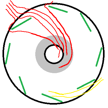
I expect it would have more rotation but at a cost of a air volume. You used the word force, "really force the air to follow." I have found that every time I think this way, I get less air. I now think with the word encourage instead of force. As stream line as possible with the smallest resistance needed to encourage the air. I have forced a bit more vortex than my current golden versions(v46) but it was so much that the flame started to shorten and spread. A tornado flame. I don't think that it was productive past a certain point and it cost me air volume. I think the vortex helps with the mixing more than air volume. I have a few versions of burners with less vortex which exceed the air induction of v46 but their flame color is not nearly as uniform in color and the flame is not as violent/turbulent sounding. The v46 flame has enough spin still in the stream that the flame is shorter, bushier, and louder. The other thing that probably works against your idea is the air induction does not behave the way we think it does. Instead of gracefully coming into one air inlet to meet the inside of the next vane, the air wants to pull straight from the outside to the center. The throat is at a lower pressure than ambient. Ambient pressure being higher, pushes air in. Imagine a vacuum cleaner drawing air down the tube. The air goes as straight to the low pressure zone as possible. The vanes being angled cause the air to go to one side easier than the other, path of least resistance. This gives angle to momentum which is the initial nudge to vortex but the vortex only has as much rotation as it has to. I see something more like the red than the yellow when playing with smoke. The other problem I see with this idea would be supporting the long flats while printing. I could use supports but then I wouldn't know how to get them out it. I could print in two pieces and glue them together. Of course, I could have it all wrong. Hopefully I do. I will give it a shot. It's a good test of my understanding of things. What OD were you thinking?
-
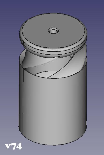
I tested v74. It's flame is in the richer range and the secondary flame is fluffy. Not so good on this burner.
-
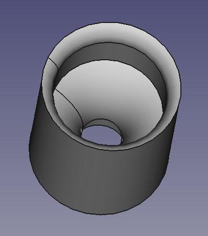
Here is version 74. Straight section is after the intake fins. I have it printed but have not tested it yet.
-
First, if you have not made the order, do not order ITC 100. Instead order plistix 900F. ITC doesn't hold up and flakes off. Plistix is also much less expensive. As to the firebrick bottom, what firebrick? Install one inch of blanket, ridgidize, and cure it. Install the second inch of blanket, rigidize, cure. Butter the blanket(spritz liberally with water from spritzer bottle) and apply kastolite in 1/4-5/8" layer. Thicker if you are clumsy with hot metal, thinner if you want faster heat up. I like 3/8" thick. Let the kastolite sit overnight then put the whole forge into a garbage bag with a wet rag. Let this sit a few days, some advise a week. Pull it out of the bag and dry the kastolite slowly. Some advise a lightbulb in the forge, some advise putting the whole forge into the oven at 225, some just let it sit a day or two, and some give it gentle heat cycles with the burner. When you do get to the running the burner, start slow. Run it for a minute or two, then shut down until cool, then run it for 5 minutes and shut it down, etc. After you have made it fully to temp and it has cooled, butter the kastolite and apply the plistix in a few thin layers until you have a fully thin coated forge cavity. I let mine dry for a day and then heated it slowly the first time. It's not too critical. I've seen people who add the kast o lite, let it sit overnight, and full out on the burner the next day without issues. I don't advise this as it increases your odds for failure, I was just pointing it out so you don't go into it nervous about not getting everything exactly perfect.
-
Wow. I will not be attempting it any time soon. I just finished CAD on v74 which is v46 with a 1 inch straight section before the reducer. We'll see what happens.
-
Unscrew it from the sand... I look forward to seeing this.
-
It's easy to make failing look easy but we are getting pretty good at it. I am glad to see the improvements in your flame. I will have to tinker with adding a section of straight before the reducer as well. I am also following the others down the 3D printer nozzle as an orifice rabbit hole. It looks like your tape may be tapered out. You may have increased the size of the reducer more than adding a section of straight.
-
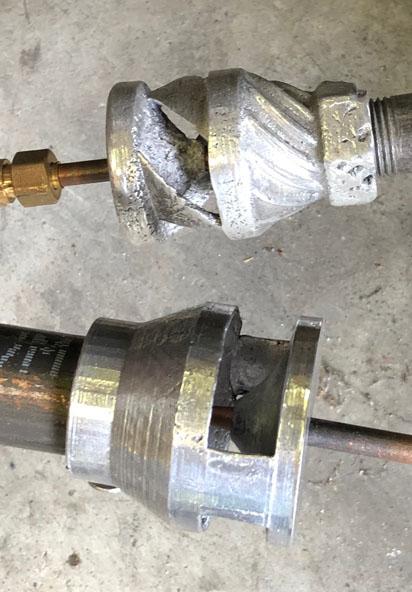
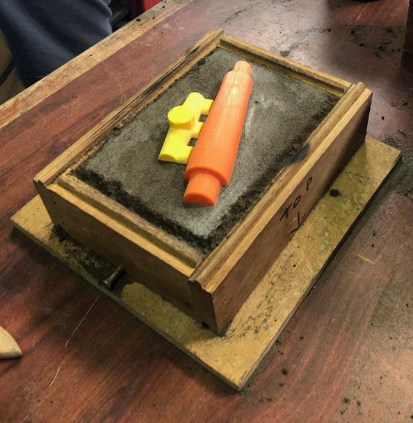
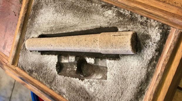
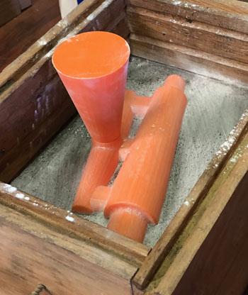
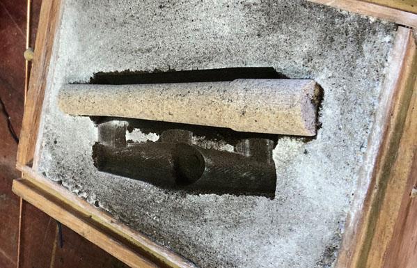
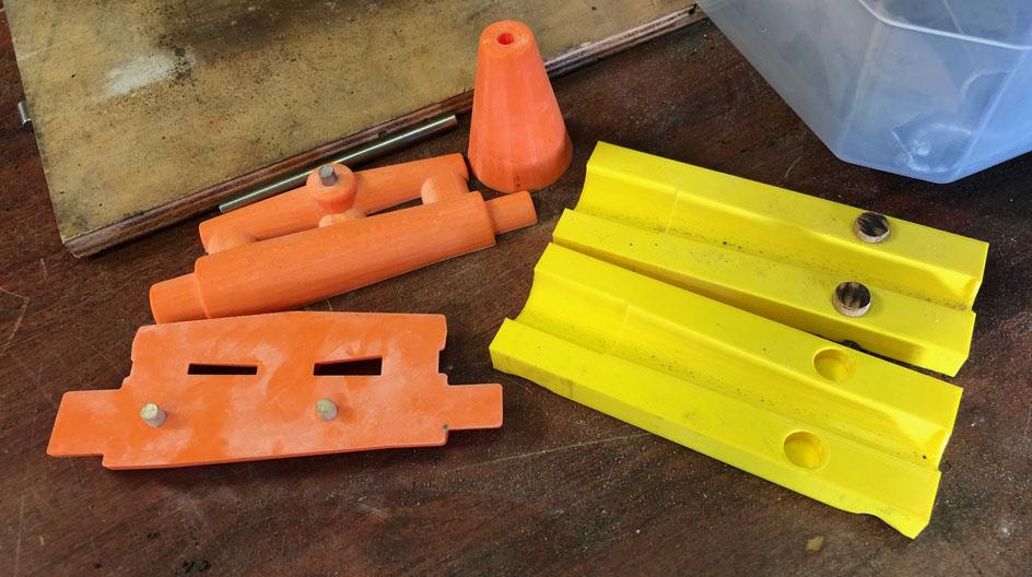
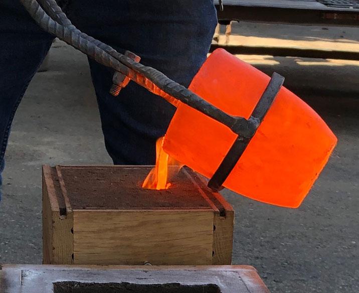
I am after a tapered iron mix tube. I designed it in CAD and then 3D printed a pattern and core mold. We also 3D printed the runner and gates. This cast failed. If you click on the image to see it's full resolution, you can make out the 3D print lines in the surface finish. We decided to make the runner longer, the gates larger, and the sprue tapered. We CAD it up and printed again. 3D printing and sand casting are a good combination. The pattern was easy to produce, splits, and has pins for alignment. The sprue has it's own alignment pin, it's tapered shape makes it easy to remove from the cope, and the taper gives us a larger target when pouring. The core mold produces a core which fits the pattern void and has exactly the taper I am after. This cast also failed. We suspect the failure was pouring too soon. Gray cast iron pouring temperature is several hundred degrees above it's melting temperature and we think we didn't give it enough time to heat far enough beyond the melted point. We will be patient on the next attempt. If that fails still, we may have to bring up the wall thickness. If you are looking to learn sand casting, I highly recommend Dan's website. I learned a lot from it. I also peppered him with questions which he happily answered. While the failures are disappointing, we are enjoying playing in the sand and pouring iron.
-
I think of flame temperature as energy density. Whereas BTU's is energy volume. A perfectly running super hot 3/8" burner puts out less total energy volume than a "colder" poorly running 3/4" burner. The 3/8" burner may be liberating more of the fuel's possible energy than the 3/4" burner but the 3/4" burner is being given more fuel so it is liberating more total energy. If the BTU output of two flames is the same but one is higher temperature, it's flame will be smaller/shorter. More heat per unit of flame area is being output. Provided similar mixing, the more air we induce, the hotter the flame. If we induce too much air, we can increase orifice diameter to increase the fuel in the air-fuel ratio which increases our btu output so long as we don't push the flame so rich that it is liberating less of the possible fuel energy. Something I am curious about, in perfect land, if you take two same forges, run them with two different burners outputting the same btu's, one being more efficient and running a higher flame temperature, it will consume less fuel but will the forge also be hotter? I ran a modified sidearm 3/4" burner in one of my forges, then I switched to my 1/2" burner, the forge uses less fuel and it also runs hotter. I don't know if this is because the 3/4" burner was running so poorly that it was outputting less btu's than the 1/2" or if the higher temperature of the 1/2" causes the forge to attain the higher temperatures. Maybe a little of both? Hopefully that all makes sense, it does in my head. After all of my treatments, I think I still have all my marbles but they are a lot more difficult to herd some days.
-
The technical papers which were shared by jwmelvin go into their findings on orifices from pages 11 through 28. They would call the mig tip a channel orifice vs a sharp edge orifice which has no length of channel. Pages 16 through 20 have a bit of information about this. Specifically they speak of gas rates per length of channel vs pressure. Here is a quote from page 16: What I found more interesting was their talk of orifice velocity vs fuel pressure and what that does for air induction. Here is a quote from page 20: Nothing being for free I guess. They do not go into the possible benefits of the channel type orifice though. When mig tips were first put into Reil burners, people were saying they made a more powerful burner. This was in comparison to the hand drilled cross tube which could be roughly drilled and also demands that the fuel change direction right at the shorter length orifice. I haven't read many people diy making shorter length orifices and the few I have read about had their burner perform better after they followed Frosty/Mikey advice to ditch the home made orifice for a mig tip. This may be due to a crude rough orifice. The more laminar jet coming out of the mig tip, punching down the center of the mix tube may be doing such great things that it is worth the loss in jet velocity. Frosty's shortening of the mig tip to tune his burners may be something worth trying on our burners. I think I understand. With jet ejectors, the jet is surrounded by a low pressure chamber which has specific intakes.
-
I look forward to your results on the new finned burner. It is looking pretty familiar. I am very happy with my burners performance but I have never put them against other 1/2" burner styles for direct comparison. I may have it all wrong but it is better than my 3/4" modified side arm in my current forge. I should build 1/2" Mikey, Reil, and Frosty T burners for some fun trials. Each burner will have it's strong points and better applications. Balance of forge and burner also being a big factor, I think. I think you have an apples and oranges kind of thing going on. Your bronze burner is in the linear category and the finned burner more jet ejector. As far as I can tell, air inlets on the side is jet ejector, not sure. I don't understand the science behind it but the guys say jet ejectors have a higher induction ratio than do linear. You are also plumbing into a ribbon burner which changes the game. With such a violent changing of direction and expansion in volume, energy has to be lost. I don't know if a loss in through put has to be accepted or if a balanced ribbon block makes some of the difference. As to the fins causing more air to be induced, I don't know that they are. In mine, there are 3 vortices behind the jet which join into one at the jet which may be causing a lower pressure zone in the eye. I don't know. I was playing with the inlet shape quite a bit and without fins, got to bigger mig tips and produced flames which were oxidizing but the secondary flame envelope was larger and fluffier. Frosty mentioned packets of unmixed fuel and packets of unmixed oxygen in Burners 101. I suspect that might be what I was seeing. I wonder if the fins are causing a reduction in total air induced but also a thorough mixing. Burning all the fuel being more important than having more FAM. Maybe? I do know that if I close the choke a third, the forge runs a little quieter and the flame still looks pretty good but the temperature drops substantially. This stuff is fun. I know more about burners than when I started but the amount of questions has multiplied.
-
That is a good looking burner Dan. Looks a lot like several of the commercial burners I have worked with. Casting and 3D printing go well together. What is the large ID of the inlet reducer? Looks to be 1 3/8" maybe? What is the ID of the reducer in your Reil Burner? With the Bordeaux modification, you have got some straight pipe before the convergent section. I wonder if this is helpful to the Reil burner performance.
-
I'm reading every word. Right now is busy season at work so I haven't had much free time to play with mud or fire I have zircopax and bentonite waiting for when I do have time. Now I have to add phosphoric acid to the toy box.
-
You already did it. Start at a lower pressure and fire it up. You can educate us as to whether it's worth doing or not. If you sight down the burner from the flame end with the mix tube still on, you can gauge the jet alignment.
-
We don't differ. What I said is wrong/backwards of what I have observed as well. My mind is slipping today. Thank you for pointing it out so I am not adding to anyone else's confusion.
-
Ron Reil called that burner a modified side arm burner on his page. You can find them on Larry Zoellers page and High Temp Tools. I believe Zoeller was credited back when with using the ward reducer with the larger side opening. Moving the jet causes more or less air induction. There is a sweet spot which will pull in the best volume of air to match the fuel volume. Generally, close to the mix tube pulls in more air. The one I have likes the jet 3/8" behind the mix tube. I have High Temp Tools 3/4" which was supplied with an 035 mig tip jet but found that dropping to an 030 tip did a better job with actual forge temperatures and fuel consumption. It was a little air starved with the larger tip. This is in my undersized forge. Maybe you would see similar. As to tube length, we would need to know the length. It looks like it might could be a little long. Have you pulled the burner from the forge? I am curious what they are using as a nozzle on the flame end of the burner.
-
There is a motor and gearbox under there. Runs 23 RPM. You got it, weighted wheel smashes the stuff, scrapers fluff it and push it back into the wheel path. We now break the molds into the muller to be run after every pour. I am still tinkering with the inlet convergent profile. When I am done with that, I can play with the profile of the cone for the jet some more. Not much fire play for us lately. Summer heat makes for busy hvac guys. I am looking forward to autumn.
