
nicole
-
Posts
146 -
Joined
-
Last visited
Content Type
Profiles
Forums
Articles
Gallery
Downloads
Events
Everything posted by nicole
-
Guys thanks for the recent round of comments, suggestions. In hindsight it is not such a shock things went dancing wildly..We will try some of these things for sure- one comment- we actually did try and heat the assembly in a large piece of pipe as an oven.. it was slow.. got impatient..perhaps to our detriment. I have plenty of stock available and so next go round will be practice on smaller lengths to experiment. Frosty's splints and tinning. Wondering out loud about how to slide the coils on the hot shaft, given they may be on the tight side when the shaft is expanded from the heat..All in good fun in a few weeks I hope :) N
-
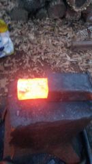
Well strike one for forge brazing. We took one set of wound threads and tack welded it onto the screw shaft with a MIG welder. Diameter is 1.5" and length about 9". Heated this up with lots of turning and fluxing on the coal fired forge. Got it hot enough to melt brazing rod and began to apply braze and letting it flow around the shaft. After cooling it was evident that the threaded keystock shifted on the shaft, spreading out in some places and bunching in others. It seemed to have a mind of its own.. Some new ideas are in play including preheating the shaft before putting the thread around it for brazing, and using a piece of pipe for the screw instead of solid..trying to control relative rates of heating of the wound keystock versus the substrate we are trying to braze it to.
-
Thomas, I am concerned about those readings on the scale too. I will have access to a much better one tomorrow. My dimensional measurements were done with a caliper; those were probably close enough. I will see what a good analytical balance gives for mass..N
-
Did a side by side spark test with an authentic piece of 52100 and it looked the same. Still need to do the rust test and thanks for the updated method :) N
-
All thanks for your comments. My research into the engineering literature on bearings is affirmed by the comments here, plus the great practical suggestions you have made to try and narrow down the field. I note that though the picture I had attached my suggest otherwise, these bearings are very much used, which is why I kept the possibility open they are cold-worked.Thanks very much, I will start playing with the stock and see how it behaves! I am interested to see how informative the density data is- it strongly suggests a high chromium alloy, so the predicted out come of your experiment yahoo2 is that it should not rust. I will have to file into one too.. :) N
-
I happened on some large roller bearings and am trying to figure out their composition. Their physical dimensions are ~1.425 D X 2.9" height, with a slight 0.050 taper. Using the tools available I calculated their density was 7.45 g/cubic centimeter. They showed some attraction to a magnet. Picture is attached. I looked up steel density and it is usually near 7.8 for a carbon steel. Chromium is less dense however and the density I determined suggests these bearings may be stainless steel; but I thought they would not be magnetic. Further reading showed that while only austenitic SS is non-magnetic, even it can become magnetic from cold working. An old bearing could be considered to have been cold worked? This seems to leave me no further along, and while this is not critical because I am just going to play around with them, it would be nice to have a little more insight into their composition. Any thoughts out there?.
-

Life is good. What did you do today
nicole replied to Jim Coke's topic in Blacksmithing, General Discussion
I started cutting my parts for my homemade smithin magician...Sunny and warm :) -
I like the idea of lapping with crushed scale and grease! As far as the strength of the system we are somewhat worried about that..hopefully with practice a technique will be developed that does a good job with minimal excess to clean. We will give the threads a torture test and if they don't bust, I guess it will be "OK"
-
Would gold plating an easier to work metal be an option?
-
 How does that work? Is there something off to the right side affixing it to the anvil or does it just cap the part you are working on?
 -
Brrr. 40 degrees here in Florida :ph34r:
-
Thomas thanks for your comments and to be sure I understand you- are you suggesting to make the box or female part longer?
-
Vaughn thanks for your comments. The length of throw would not need to be much more than a few inches..but..having a longer screw may be advantageous in terms of what is yet to come..parts of the screw may be better than others..who knows..it just seemed like a good idea to use the extra coil for that. maybe it will become "practice"! Seems a lot of fiddling around will be happening. Charles that sounds like a great suggestion thank you; today we also talked about running a small wire wheel along the threads to clean out flux and loose stuff. It looks like the next step will be to learn to forge braze on scraps that increasingly start to look like what I really want to braze so the odds are a bit better.
-
Dan, thanks for the heads up on the spacing..the photo is misleading.. the screw does have irregfularities in it being hand wound so as those get worked out we can be sure to leave some wiggle room :) thanks
-
Thanks for the encouragement..hopefully tomorrow will bring some good news on practice forge-brazing..
-
Hi All, I am working on making a large vise for smithing. I got a bug to make my own screw and nut by semi-traditional means, hence this involves winding a 1.5" diameter rod with 3/16 keystock, paired up so as it is wound, the threads for the nut are created too. I am doing this with my smithing mentor and we are learning as we go. I welded a guide to the rod to help get the pitch correct and tacked the ends of the two 3/16 keystock pieces so they would rest against the guide. Wrapping was done with two people working in tandem with an oxypropane torch and a hammer with the form rod held upright in a vise. It was tricky getting the helices separated and off the rod..it required some hammering in a swage block to slightly expand the coils so they would "slip" off the rod, as well as some precision prying with a screwdriver. Still much more to do. In the photos I show the fully wound coils on the form rod. The nasty looking bump on the right side is a splice that I mig welded in so as additional 3 foot pair of keystock rods could be added to the coil to reach a full 9" wrapped length. The splice was a piece of heavy gauge sheet steel intended to bolster the butt-welded keystock during the wrapping process. The other photo shows the two coils separated from the guide rod. One coil will be cut in half and forge brazed into a pipe for the nut, the other half will be spliced onto the longer coil and this will be brazed on to a support rod for the screw. The vise leg and moving arm are made of 4" steel channel and the jaws started from 2 x 2 x 8" mild steel that I machined on a mill. I have welded up the jaws into the channel and learned I am a better grinder than welder. I hope to change that someday :) I will send up more pictures after this weekend. I am enjoying the journey. The vise is less important..as has been pointed out.. I could have bought a decent used post vise already :)) Nicole
-
Hi Ancientsword, welcome. I am a novice smith in Florida too; I recently joined FABA, the Florida Artist Blacksmith Association which is also a wealth of talent and inspiration http://blacksmithing.org/
-
Thanks bigfoot- your comments are super helpful, and since the piece is still in my shop I will reinspect the piece. I will also solicit feedback from my friend as he tries this and see what matters to him. Thanks! It is a bit of a strange exercise making a tool that I do not or have not ever used myself! Nicole
-
Thanks for your comments! I am not a wood turner and I was copying another model my friend had shown me that was flattened in its profile. There is plenty of stock there to grind on if need be :) I anticipate making a universal type tong today that will get me one tong closer to having all the tongs I need ;) N
-
A friend of mine has an old wood lathe and had trouble finding an S-type tool rest with a 7/8 post. What I should have done was make him a sleeve for a smaller commercial post; instead I made him the one shown here. I used 3/4 stock for the rest and 7/8 for the post, both in mild cold rolled steel. The rest was shaped on a swage block, and then flattened out on the anvil. I used a 2' length of rod stock for the rest because A) I didn't have a suitable pair of tongs and B) I felt that given how hard it was to move 3/4 stock I wanted to keep a good grip on it. I cut it down to length after the forging. A 1/2" hole was drilled in the center of the rest. The post was turned down to 1/2" 3/4 " from one end, and shrink fit into the rest. For the shrink fit I heated the rest to red with a torch and drove the post home with a 3 lb hammer. I then filet welded over both sides of the post and used an angle grinder to clean up the profile. I welded a bit of 1/4 stock on the post as a stop. It proved to be tricky for me to make a ring out of the 1/4" stock. I do not have appropriate tongs for this; I used vise grips and did much of it on the anvil horn. I think that next time I make a ring I will have fabricated some sort of a jig for this task. Though this was a lot of work, for what I thought would be a simple project, I learned that 3/4 is for sure the upper limit to what I can forge by hand at this time. It took quite a few heats for me to shape the rest. I also learned that I need to make more tongs!
-
slowly getting the smithy together. Progress on the homemade post vise and my welding table is built
-
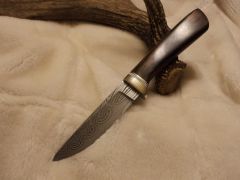 Lovely pattern! (and knife)