
knots
-
Posts
734 -
Joined
-
Last visited
Content Type
Profiles
Forums
Articles
Gallery
Downloads
Events
Everything posted by knots
-
Very nice Beth. If I am understanding correctly we are looking at several individual pieces sort of piled together and ready to go to market. No doubt that they will sell as individual pieces . However, I think I also like how thes seperate pieces work visually when assembled in gorups. I guess what I am saying is that I see an opportunity to put these kinds of pieces together as sculpture. When I look at those random assemblages that is what I see.
-
To achieve the full potential of it's holding power the vice must be bolted to a bench or post that will not move under the largest force that you will apply to it. Sounds like you are planning to use a bench. If the bench is not heavy enough to maintain stability when working there are two choices. Bolt it down or ballast the bench to keep it from moving. My shop is much to small for all of the stuff that I have so I built my bench with a grillage low in the base where I stack concrete pavers and buckets of steel scrap to act as ballast. That allows me to move the bench without having to deal with bolt studs in the floor.. Your bench can be bolted to the floor or to a wall to provide stability. If portability is needed ballast is the way to go.
-
I bought one back in 1986. it weighed about 125 pounds and rang like nothing I had ever heard before or have since. Took it home used it three times and sold it. The ringing could probably be dampened, but the anvil was just to narrow and the heel was not suitable for the work that I was doing. Even though it didn't really suit my needs, I still sort of hated to see it go because it was a cool anvil . In retrospect I think that it would be a good anvil if your work included a lot of light forging on/of small stock. An example would be forged jewlry, or small hardware items. For general forging it is hard to beat a more robust anvil.
-
The photographs below are tooling that I made up for my Waterbury Farrell Press. There are three sizes of tool holders. 1" dia. is the largest . The smallest was made to fit a standard size of pneumatic demo tool chisel which has a preformed shoulder ( .70" ). One thing that you will probably have to deal with is that the dove-tailed work plate comes with the press is ( on mine at least ) hardened and is to hard to drill or file. Consequently I machined a second dedicated dovetail plate for mounting my tooling. After completing that task and getting the tooling installed I realized that an alternative would have been to drill mounting holes into the bottom of the press ram. This would have given a couple of additional inches of clearance if needed. In my case the additional clearance is not needed. So far the tool shoulders are the only unresolved issue for my set-up. At least on the larger diameter tools I need to resolve some shoulder welding issues and complete fabrication of the tooling. The shoulders are needed to keep the tool from bottoming out in the tool holder and mushrooming. I plan for all of my tooling to be shouldered so the tooling holes are bored completely through the mounting plate to allow stuck tooling to knocked out from the bottom.
-
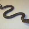
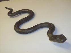
Friend Found "This" Any ideas?
knots replied to Wesley Chambers's topic in Anvils, Swage Blocks, and Mandrels
How about some sort of work surface for repairing trawler nets, or splicing ropes. The pointed end could have been for untying knots to allow repair. -
How do you prepare a stump for an Anvil?
knots replied to Borntoolate's topic in Blacksmithing, General Discussion
There are several postings in IFI regarding using a router to level stumps. I have leveled 4 stumps so far using that method. The beauty of the process is that both ends can be made both flat and parrallel. Your stump looks like a keeper. If it cracks squirt some glue in the crack and tap in some shingle shims. If you really want to stabilize it bore and countersink for all thread rod. Snug it up and keep forging. The last stump that I prepared got moldy on the bottom. I brushed on anti freeze to stop that. There is a thread here in IFI on that subject as well. There are some precautions that need to be observed regarding the toxicity of anti freeze, so be sure to look that thread up if needed. -
Nice texture ! Excellent explanation of tooling. All of my sculptures include reptiles. Never have textured them though.
-
I have a right to know what you know
knots replied to ciladog's topic in Blacksmithing, General Discussion
My understanding of entitlement is that it either must be granted or earned. This forum grants entitlement to a wealth of information both to menbers and to non-members by the simple gift of access to a massive quantity of valuable technical information, opinion, experience, and insight. As with life not all gifts are understood. Their value and relevance may not even be recognized, or even possibly ever fully accepted or appreciated. Do you have the right to know what I know ? In the global sense, no. At least there is no obligation on my part to provide knowledge or information to you that I do not wish to share. To the contrary it is my entitlement to choose to give that information up to you or not . The fact that many choose to freely offer the gift of our views and experience is what makes this forum worth the effort to read and post to. It also makes the inevitable misunderstandings and mis-steps tolerable. However, once posted, any un-copyrighted content on this forum becomes public information and accessible to just about anyone. This includes the robotic programs that sweep everything into the cloud. This entitlement is granted by the simple act of placing information into the public domain for all to see and use as they see fit. Ultimately we must each find our own way . The gift of shared information should serve only to make that task more accessable. Staff Correction: all postings on IFI are Protected under international copyright laws, so there is no such thing as UN-copyrighted material posted. -
Yes, a nice Jacobs chuck will be an essential part of the kit. However If large diameter holes are to be drilled, the tapered drill bits are keyed into the base of the taper to prevent bit rotation in the taper under load. If large holes are to be drilled a selection of the larger keyed tapered bits are the way to go. Without them the potential of the drill press will be hard to achieve. Using the Jacobs chuck for smaller holes is the way to go, but they do have their limits.
-
MiG welding a steel pipe to a perpendicular base plate
knots replied to Tooneyman's topic in Welding/Fab General Discussion
In the past, when it really matterd (which is not to often) I have drilled a hole in the base and used all-thread to temporarily clamp the pipe to the base. If you get a good true to square cut on the pipe, the pipe will be held in place and you should be good able to get a good square weld. If the cut is not exactly square use shims to square the assembly up, torque it down and weld away. -
I finally made it back to my old shop for another load of machines & materials . I found only one MT shank drill bit in my scrap tool steel bin. Unfortunately the large end of the taper measures 1.76" Diameter, indicating a No. 5 MT. The drill is 1 5/8" diameter, Mfg. by National, and is high speed steel. At one time I had a bunch of MT drill bits that I purchased for tool steel stock. Looks like this is the last remaining one. Seems a shame to cut it up for material but that seems to be it's coming fate unless someone wants to pony up postage for it. BTW the bit will need to be reground If used.
-
Marking Hot Metal For Precision Work
knots replied to iron quake's topic in Power Hammers, Treadle Hammers, Olivers
The square punch works suprisingly well. I made mine from a smallish ball peen hammer. -
unusual Peter Wright
knots replied to Old South Creations's topic in Anvils, Swage Blocks, and Mandrels
I think that you are right. Probably will never know who made it. But I really like the compact form . So I think that it is about to become my main anvil. It will be a couple of weeks before I can get around to posting it but will make it as high a priority as possible. -
unusual Peter Wright
knots replied to Old South Creations's topic in Anvils, Swage Blocks, and Mandrels
" Soooooooooo....here's what I now believe I have....a pre 1852 Peter Wright farriers anvil " Well yes. It most probably is. But I should have been more precise in my statement rearding the punch marks . There are what appear to be two punch marks in about the correct spacing but lower than the existing weight code marks. One is very clear but the other looks have to hammered over. My logic was that if rebuilt, the anvil would likely have weighed more or less and needed to be remarked. I was just thinking out loud. And yes speculating since others have suggested this anvil may have been a special order. My problem is not with your anvil. It is with the erronious labeling which further clouds the identity and intended use of my anvil . It's weight is almost double what a farriers anvil is usually sized. I intend to post pictures if it. However I will need to remove it from it's stump, truck it down to my local Southern States and beg them to weigh it before starting a new thread. After all bathroom scales can be significantly off if the object being weighed is in an awkward position. Certified scales will remove the uncertainty. Thank you for this interesting thread. I look forward to your thought and comments when I finally get mine weighed and posted. -
unusual Peter Wright
knots replied to Old South Creations's topic in Anvils, Swage Blocks, and Mandrels
"It doesn't look like any carriage makers anvils I've seen. All of them that I have seen have an extra table on the side.Someone please correct me if I'm wrong." My copy of AIA arrived yesterday. It is going to take some time to research just the areas of most urgent interest. However I did find an illustration of Standard Pattern Mousehole Anvils on Page 80 ( published in 1919). The pattern illustrated under the heading "C" is a good match for my unmarked anvil . In the text below it is identified as a "Coachsmiths" pattern. How ever on page 93 the Brooks and Cooper Mousehole Forge Illustration identifies a similar anvil as a " Farriers anvil". I suspect that the difference is that the coachsmiths anvil is a heavier anvil (mine weighing about 300lbs) where as the smaller anvil would likely some what lighter if used by a farrier. Even though my anvil has no markings of any kind, that I can find, these illustrations of anvils of similar shape begin to indicate not only a tentative date but what anvils of this shape were used for . Possibly even as a type of industry standard shape standard of the time. So maybe mine is an anvil produced in the Mousehole Forge in their declining years. Maybe/maybe not. It seems likely that more options will present themselves. This is going to be a good read. Edit: In reading AIA it seems that many of the anvil makers performed repairs on old anvils. Could featured Peter Wright anvil be a reworked Mousehole anvil repaired and remarked by the Peter Wright works ? The hundres weight marks have the dots between the numbers, a classic Mousehole identifier. -
My shop is small and dusty. Therefore I clean and relube the screw press frequently to control the contamination of abbrasives. No doubt there are beter idustrial lubricants but frankly I am concerned more about wear from contamination than anything else. The top quarter of the perimeter surface of my screw have fine threads cut into the press screw. These threads are not a functional part of the screw but to act as an oiling system. The machine was designed to be oiled. My press is a Waterbury Farrell patterns makers press. Thanks to ptree for his valuable and authorative in put. I suppose that i will get some of th GN for use on other screws, and for specific heavy runs on my screw press. Hmm - maybe an old rain coat over the press would solve the contamination problem. It is a tiresome chore to keep it clean . ptree - Slightly off topic but is the GN product suitable for lathe gearing ? The grease that I am using now is a moly based general purpose grease which I also use on my chucks.
-
Way Oil
-
Before I got a mill I made a couple of sets of dies on my radial arm saw using a grinder wheel in lieu of a blade. It worked just fine. There are a few problems that you need to be aware of so that you can protect and compensate. First of all, there is a lot of dross thrown off so you need to wear a respirator and eye protection. There are a lot of sparks so there is a need to be careful that the spark stream is deflected or contained so the you do not set your shop on fire. Move your machine outside if possible. A simple jig made out of plywood to hold the work piece in stable alinement and at the correct dovetail angle and keep the piece alined is all that you really need. Just take light cuts and push the grinder stone through from the front of the saw rather than pulling as the saw is normally used (otherwise the wheel just climbs the work piece). I think that jig is still around in my old shop maybe I could retreive it for a photo opp in a week or two.
-
Very nice. What does the flip side look like ? Looks like the holes go through which would mean no spoon or bowl form depressions. However you might check out to see if the smaller squre holes are tapered to receive tinners stakes. I have one that has tapered holes. It is a favorite of mine.
-
air hammer swage dies
knots replied to ironman186's topic in Power Hammers, Treadle Hammers, Olivers
"Alpenschmiede Special Die Set with Stock Guide". These are what I was talking about and Centaur is closing out these dies. Their stock may not include the die configuration that you want but you will at least be able to see how Kuhn made their dies. If they don't have what you want you might consider purchasing a set of flat dies to make your own custom die from. -
air hammer swage dies
knots replied to ironman186's topic in Power Hammers, Treadle Hammers, Olivers
Back when I bought my Kuhn there were a series of product sheets describing matched pairs of open forging dies . The implication was that they were a Kuhn product. I still have a few of those data sheets and although I never purchase a set it looks like a good idea that would apply to handles or balusters. The dies were identical top and bottom dies with the profile machined right across the die. When installed in the hammer with the features registered in alinement. The work piece was forged from the end of the die while rotating. This gave a uniformmly forged profile over the length of the die. My hammer and this literature came from Centaur Forge. Although I doubt that they have the dies available the concept seems a lot more feasable than the use of closed dies on a power hammer. This die concept has to be old technology. I would post pictures except for possible copyright infringements . Maybe Glenn can weigh in on that issue. I hope that my description of these die sets are sufficient to get the idea across. Happy forging. -
unusual Peter Wright
knots replied to Old South Creations's topic in Anvils, Swage Blocks, and Mandrels
Pritchel hole ? Yes, and with the bulge -
unusual Peter Wright
knots replied to Old South Creations's topic in Anvils, Swage Blocks, and Mandrels
John - Truth is that I still have no idea who made mine, and I may never know. All that I do know is that mine sure looks like yours and I find that of interest . Back when I first got mine I looked into mousehole anvils and found an anvil which had no table and looked like mine that was labeled a carriage makers anvil . What ever they are I really like the compact sturdy shape of these anvils they put a lot of mass where you need it. That is under the hammer. -
unusual Peter Wright
knots replied to Old South Creations's topic in Anvils, Swage Blocks, and Mandrels
Well I have one that looks like yours, however there are no markings on it. Mine weighs around 300 lbs . I believe that the anvil is a carrage makers pattern anvil. Last week I finally ordered up a copy of "Anvils In America" since a recent thread cast doubt on what the anvils that I have are. This is just another example since I have always assumed that mine is an un-marked mousehole. Is the plate on yours a single piece of steel or two. Mine was forged with two pieces and has a slight sway where yours appears to have one. On mine the edges are still intact, a bit rounded from use but with no chipping . Both solid citizens for sure. -
Use a small channel with the flanges turned up below the rail cap and down for the bottom rail. Drill or punch holes tor the pickets in these channels. Make the pickets a bit longer so that you can stick them through the channel from the flat side. Weld the pickets from the inside between the upturned flanges of the small channel. This will make all of the welds concealed when you cap it with the railing. Edit: John B has it right (below) for railings that need to historically correct, and/or high end iron work where cost and time are not a real factor. The method given above is more or less standard fabrication tecnique for railings where the owner doesn't have the budget to pay for all of that traditional joinery and yet exposed welds need to be avoided.