Alan Evans
Members
-
Joined
-
Last visited
Everything posted by Alan Evans
-
@ Dale M sorry my smiley did not make it to the post:) @ JJ if you have not committed yourself yet I would be inclined to cut out the wet tue experience altogether and go for a bottom blast fire. The only advantage I found lacking was the simplicity of a tight fire for punching or welding, for everything else, especially when you get a power hammer and want to do longer lengths the bottom blast is far more versatile and maintenance free in my experience. Alan
-
+1 You can increase torque easiest with a longer lever. The longer lever is more radical but for an everyday improvement you can put a ball race in place of the washer on the thread spindle. Standard ball races will cope with a few tonnes of end thrust, angular contact or spheroidal roller bearings will obviously do more.
-
I am intrigued, why would you lose metal at each end?
-
@ Jeremiah Johnson The straight tube tue works fine, I would tilt it the other way so that the tip which is the hottest part is lowest point, so that the thermo siphon will take the water away. The one I used initially (for five or six years) had an end plate both ends and I had a couple of car heater hose (1/2") rubber pipes feeding in to an old oil drum as a remote bosh which saved making a bosh and trying to get a water seal around both air pipe and water jacket. I do not quite understand your drawing. You show the thickness of the metal of the end plate but not the tube wall or the baffle. I am baffled by the baffle! Just one tube inside another should be adequate.
-
-
I bought my 100 tonne Finlay horizontal press from the British Rail workshop in Southampton when that closed down. It came with a few sets of tools for bending the various profiles of rail. Some on the floor in the foreground of the picture. It may save you some reinvention time! The press will bend 100mm (4") square cold. I generally do any radical bending hot for safety's sake.
-
S/S Chestnut Roaster


-
If the screw(s) holding the nut/thread block in place have fallen out you should be able to see where it should be and wriggle the nut into place (by turning the tee bar and jiggling with a screwdriver) and put in another, it may be an early thread form so unless you can match the thread exactly a piece of brass or aluminium may temporarily align the nut block sufficiently without damaging the threads. Is this a known vice, was it formerly your fathers? I ask because there is a shiny section on the side of the channel section which could be a weld repair clean up. If that has not been cleaned up well it may be causing the jam, the vice only looks half opened in the pictures....
-
I had the dreaded SQL error failed upload message again and the images do not appear to have uploaded, this is from another computer... third try Macbook on the forge broadband ah! success at last
-
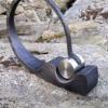
How long ago and what do you consider is history? :) These images may help with some of the practicalities, if not the traditional form of metalwork you are looking for. They do however have a valid blacksmithing history! I made these bits to clamp on a 20mm (3/4") diameter shaft ten years ago for my 50th bash when we roasted "Sam the Ram" over 40 blacksmiths were in attendance. They were used again to roast two home grown pigs at Rebecca and Chris' wedding at Terry and Sally Clark's home. The bride (Terry and Sally's daughter) is a blacksmith and Chris who has the right shape isn't! The bride and her father walked in through an arch of hammers held up by blacksmith friends. The bride and groom were married over the anvil in touching ceremony presided over by two blacksmiths culminating in riveting together two bits of metal. Rather than employing a spare kitchen boy to turn the spit continuously I found that a bit of tube slid over the appropriate windlass handle allowed four different aspects towards the fire and locked it for a bit at each point. Use blocks, an upturned bucket or a different length of tube if you want an 1/8 rotation. The weight always is eccentric however carefully you tie the carcass on so the windlass always wants to rotate one way or the other. Not shown would be another set of posts to rest the spit on away from the fire for carving. The cook at the wedding just lifted it onto a table. Alan
-
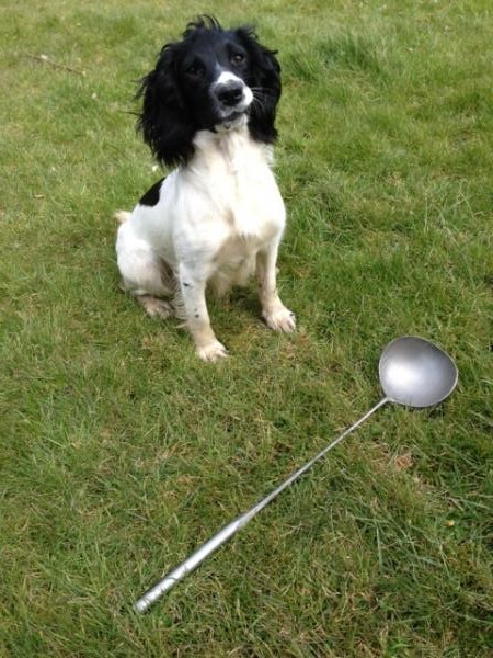
Something odd going on, with either the forum, my computer or my internet providers... my earlier posts do not seem to be registering properly. I attach a couple of images of a Chestnut Roaster bowl mentioned in the earlier post. This one was forged from 20mm diameter 316 ss and you should be able to see the rib marks from the spreading in the bowl close up.
-
I use a carpenters wooden mallet and a lump of oak to straighten things like the twist, used with the metal at forging temperature it does not bruise the twist corners. Bit of smoke of course! I like your irregular basket! The human hand is amazingly versatile in what it can comfortably grip and often an irregular form gives a firmer hold. When I was devising handle shapes for fire tools I squeezed a bit of plasticene of the same size and shape as the work piece and then forged a simplified version of that. I have never made a basket but the smith I worked with always used to cut up a piece of the same rod into short sections and used that as the core of the basket bundle. The end pieces added meat to the weld and when he untwisted the cage the other pieces fell out. Alan
-
Odd. When I clicked on post I had an error message saying that the SQL server had failed or something, but it then loaded twice? The thread does not seem to have updated on the main forum list either...oo-er. Alan
-
@ Kurgan, your 4.5' grinder with 1mm slitting discs would do it before this Easter no problem! I dug out my bowl tools and made a video to show you my press tools at work in real time. It should give you an idea of the ring /tube support and the tools' efficiency. A small flypress and an hour or four making the tools and away you go!.....http://www.youtube.com/watch?v=e6aYzjaEffk The system was originally made to sink the bowls for some gates I designed in 1983 at that time I only had a number 3 or 4 flypress and it coped fine with the 8mm (5/16") bowls. The second video describes how they were made and attempts to explain why large / mushroom faced hammers or top tools are so very much more efficient than an ordinary full faced hammer as I mentioned briefly in my first post on this thread. http://www.youtube.com/watch?v=6KcV_jkU4y8 In the videos I am only pushing in some bits and pieces I had kicking around, all from standard sheet or plate. One of the big advantages of the system is that it could cope with plate/sheet that had been forged. I used to make a lot of shovels and chestnut roasters forged from a piece 16mm (5/8") square, I always liked to leave the rib marks from the spreading process visible but it did mean the sheet had thick and thin spots and sometimes (with an extra blow in the wrong place!) extremely thin bits which would buckle easily when the bowl was being formed. Alan
-
Indian ink, Chinese ink...the mind boggles! Personally I speak fluent pencil... to the OP, I am sure you will be fine, especially with TechnicusJoe and schilpr on the end of an email or phone line! As part of my teacher training I studied educational psychology at college, after three years it all boiled down to Confucious:- I hear and I forget I see and I remember I do and I understand From my experience of many journeymen working with me, with some of whom I shared no common language apart from blacksmithing...it was all that we needed.
-
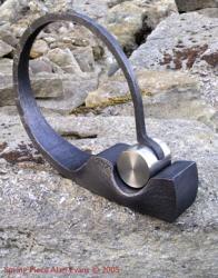
Why fix to a stump? I always favour versatility and would be inclined to mount them by supporting the outside diameter on a ring (you may not even need the plate) then they could be used on any flat surface, floor, bench, anvil, stump top, fly or hydraulic press base... Better still make a ring or tube base then you can drop any radius bowl former in depending on the shape you want to make. If the bowl you are forming is larger than the tool you are only putting pressure on the rim of the dish tool so that is where the tool needs support. I made most of the large bowls and the tools in my photo earlier in this thread from scratch by forming a 175mm ring from 16mm round bar and welding it to a short section of pipe it is only the rim that you use and it must have a soft edge to avoid a load of crescent shaped bruises on the outside of the bowl you are making.
-
In the The Blacksmith's Craft the book published by the Rural Industries Bureau /Council for Small Industries in Rural Areas in 1952 the illustration of an anvil describes it as a 'Tool Hole'. In the text it describes the two holes in the anvil... "the square or hardy hole and the round or punching hole. It is a good plan to chamfer the edges of the square hole so that the hardy sits tight to the anvil face; this is also a convenience when using the hole for setting slightly curved bars." In the tools section a few pages on it has:- "HARDIES Hardies are chisels which fit into the square hole in the anvil, the work being driven down onto them. Some smiths make one fairly stout hardie and use it for both hot and cold work, but it is better practice to have two separate ones suitably shaped and tempered for each purpose." So they used all the variations within a few pages...and not just 'y' for singular and 'ies' for the plural...
-
I have always known the round hole as a 'pritchel' hole never heard of spud before... The Practical Metalworker edited by Bernard E Jones originally published in 1900 refers to the Anvil Set or Hardy and illustrates a cold set in the hardy hole.
-
Is that Oxford Miss. Mass. Or the 51st state? Could make a difference....though I guess it hardlie matters.
-
I am glad you got it sorted. Every time you have a major burn back you should give it a decoke. The soot inside can build up over the years however, every time it pops because the nozzle got too hot and the gas pre-ignites/burns inside. I was always told to lead with the fuel gas for both lighting and extinguishing so you are sure the flame is out. If you turn the oygen off first the acetylene flame burns back and into the nozzle and 1) you can never be sure it is fully out 2) it deposits a bit of lamp black/soot inside the nozzle/burner tube. In the Victor book that I had with the torches it gave a basic lighting procedure:- 1,Set both gauges to deliver the indicated book pressure for the nozzle, allowing for pressure drop with long pipes. 2,Check flow by opening (and closing) the torch valves individually whilst watching for any gauge drop (especially important for cutting oxygen) 3,Light the acetylene, turn the torch valve up until the flame jumps off the end of the nozzle. 4,Turn it back down until the flame just jumps back to the nozzle. 5,Turn on the torch oxygen valve(s) and set the flame to remove the oxygen feathers on the cone. On the rosebuds I usually turn the acetylene valve up a tiny little bit after stage 3, but not enough to pop the flame off the end again. The welding and cutting torches I leave at 3,. This is from memory of thirty years ago and is what I have done ever since...it would pay to have a look in the book or on the Victor site to check for yourself. The advantage of following this procedure is that you can spot any problems immediately if the flame does not react as it should. Alan
-
Given the pressure information the OP has posted the 1/7th draw is the least likely fault I think. Given that he has tried different pressures and presumably has set them as per the Victor book he quotes, for the 1/7 rule to be the cause both acetylene regulator guages would have to have failed simultaneously...with one showing falsely he had contents and the other that he was achieving the book pressure. When he can answer the questions we have all posed we should be able to diagnose the fault. It does not read as though he got much further than trying to light the torch, so over heating the nozzle does not appear to be the problem. It would appear something in the mixer, burner pipe or nozzle is blocking it and reducing the flow of gas. Hillbilly's post would appear to answer the information we have been given best. I await developments with baited breath!
-
It would be interesting to know if there was a noticeable advantage power wise with either rotation. It can only be a few degrees of crankshaft rotation difference say 175˚ in one direction and 185˚ the other. My clockwise direction takes the quicker 175˚ on the compression/upstroke which does mean the acceleration is slightly more rapid and thus a faster tup downward speed....which should be advantageous. We will have to ask everyone we know with an Alldays to see if they have noticed a difference and which direction theirs go. Alan
-
If the cutting torch works okay then your oxygen side is okay, something is restricting the necessary high fuel gas flow presumably. Is it definitely the correct nozzle for the gas? I have both propane and acetylene rosebuds for my Victor torch....and I also have a lamp blacked ceiling from when my assistant tried to get an acetylene flame balanced on the propane burner which he had put in by mistake. :( You have presumably had them working before if you have changed the O rings, anything else changed? New longer or smaller bore pipes giving a pressure drop? Fuel gas Pressure gauge not reading correctly? Try another regulator set. Burner pipe seated properly in mixer/connector, no blockages or leaks? Is it burning back inside the nozzle immediately on light up, or popping after a bit of use caused by a hot nozzle again caused by fuel gas starvation? Alan
-
Thoroughly confused now with back and back end! I stand either in front or to the left or right depending on which hammer I am using for either tooling or hammer location reasons. So I keep it simple with front, back and then left or right when viewed from the front! I do not remember noticing the Alldays off set crank in all the days I spent poring over the drawings before installation or in all the years I have had the hammers! What a confession. Mine have both been running in clockwise direction since I have had them (25 plus years) so even if wrong it does not seem to be disastrous! I would prefer to have the compression stroke with the con rod most aligned with the axis of the cylinder...but the motors definitely moved about in that direction...hmmmm. Possibly it is to do with the relative efficiencies of compression and vacuum on a single acting hammer? The vacuum stroke takes longer in my configuration. Ah.... I have just reread the installation brochure...I have it in .pdf form if anyone is interested...it happens to mention in 6th paragraph first page ...that on motor driven hammers you should graphite and grease the gearing before fitting the gear guard... Then "Belt Driven Hammers are fitted with fast and loose pulleys and belt striking gear and may be run in either direction." So I guess it does not matter as far as the crankshaft and conrod are concerned, so revert back to John's safety point and my wobbly motor reason. Alan
-
All of my major kit is old and I certainly could not have afforded it new. I have only one new out of 5 welding machines, and one of the 5 hammers I own was nearly new...my 50kg Reiter was ex 1980 Hereford Conference demonstrator. I have photographs of many of the crowned heads of the world forging on it! One advantage to living in a post industrial age!