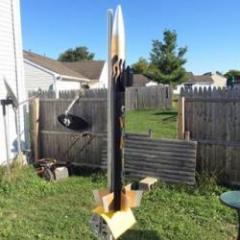
SwampFox Rocketry Posted May 14, 2018 Share Posted May 14, 2018 (edited) Trying to find out if these burners are up to par for a propane forge build. I have acquired these burners from a friend that built the forge for me and trying to get some thoughts as if its burning well. This is my first go at blacksmithing and learning a lot but have no experience. I know these burners are using .025 mig contact tips and about 7 psi of gas to them before flame blows out. I've have yet to try them out as refractory is still coming in mail to finish the forge lining. They may be fine may not but wanted to share and get some opinions from the experts. I was concerned with the flame size compared to other burners on you tube and was wondering if they seem adequate or not. Thanks for any input. Mike. 2018042295182542.3gp Edited May 14, 2018 by SwampFox Rocketry Notifcations to me Quote Link to comment Share on other sites More sharing options...
Irondragon Forge ClayWorks Posted May 14, 2018 Share Posted May 14, 2018 Hi Mike, welcome to IFI. The burner guru's will be along in a few. In the mean time I suggest reading this thread. https://www.iforgeiron.com/topic/48833-read-this-first/ Quote Link to comment Share on other sites More sharing options...
SwampFox Rocketry Posted May 14, 2018 Author Share Posted May 14, 2018 Will do thanks! Quote Link to comment Share on other sites More sharing options...
Frosty Posted May 15, 2018 Share Posted May 15, 2018 Welcome aboard Mike, glad to have you. I don't see any pics of the burners running so I can't give you an opinion or suggestions. More pics please, we LOVE pics. Frosty The Lucky. Quote Link to comment Share on other sites More sharing options...
Idk Posted May 15, 2018 Share Posted May 15, 2018 Welcome aboard Mike. Oh Mr. Mike is going to have fun with this one. Might I recommend reading Burners 101. It covers and thoroughly discusses just about everything to do with NA burners. https://www.iforgeiron.com/topic/46536-burners-101/ Mr. Mike’s post entry #26 on page 6 of Burners 101 addresses the design of your burners. Also suggest you definitely read it as well. I like the Mikey burners (personal preference) for my application(s) due the ease of fine tuning. Quote Link to comment Share on other sites More sharing options...
Mikey98118 Posted May 15, 2018 Share Posted May 15, 2018 It isn't too late to turn those rolls of holes into a slot at least. Rectangles with bels for and aft would be even better. Three slots. Input Mikey burners on the web and loads of information comes up. Also, reverse your mixing tube; it's positioned backward to what you need as is. Quote Link to comment Share on other sites More sharing options...
SwampFox Rocketry Posted May 15, 2018 Author Share Posted May 15, 2018 2018042295182542 (3).3gpThanks guys yes i found the 1/2 mikeys burners and it does look like these. Ill also do my reading in burners 101 thanks IDK. And mikey and frosty. I posted a vid in the link under my question of burners in action ill try again and get a pic too. I like the idea of making the holes into 3 slots as i have 3 sets of holes drilled. The bad part is there not straight. I thought about just getting new tubes and starting from new ones would be cheap and easy fix to get a symmetrical slot section for the choke. Thanks guys. Quote Link to comment Share on other sites More sharing options...
SwampFox Rocketry Posted May 15, 2018 Author Share Posted May 15, 2018 Mikey for this part of ur comment Also, reverse your mixing tube; it's positioned backward to what you need as is Do you mean I should have choke near the flame side with the slots for air? I'm a bit lost on this suggestion. Quote Link to comment Share on other sites More sharing options...
Idk Posted May 15, 2018 Share Posted May 15, 2018 With all due respect for Mr. Mike a picture is worth a thousand words. Here’s how I build my Mikey burners. Quote Link to comment Share on other sites More sharing options...
SwampFox Rocketry Posted May 15, 2018 Author Share Posted May 15, 2018 Mikey for this part of ur comment Also, reverse your mixing tube; it's positioned backward to what you need as is Do you mean I should have choke near the flame side with the slots for air? I'm a bit lost on this suggestion. Ill get more pics not at the house now looks good idk. Quote Link to comment Share on other sites More sharing options...
Frosty Posted May 15, 2018 Share Posted May 15, 2018 I think Mike means reverse your choke tube. reversing the mixing tub doesn't make any sense, I think it's just a typo. Having the set screw where it is severely limits the travel of the choke, it can't lock the tube if it's over an air inlet. Frosty The Lucky. Quote Link to comment Share on other sites More sharing options...
SwampFox Rocketry Posted May 15, 2018 Author Share Posted May 15, 2018 Ok i got what ur saying. I will i plan on cutting those holes out and going from there as well having the long openings vs holes to keep the design. Like mikeys burners. Thanks for all ur advise everyone. Ill keep u updated ! Quote Link to comment Share on other sites More sharing options...
Mikey98118 Posted May 15, 2018 Share Posted May 15, 2018 1 hour ago, SwampFox Rocketry said: Also, reverse your mixing tube; it's positioned backward to what you need as is Do you mean I should have choke near the flame side with the slots for air? I'm a bit lost on this suggestion. Ill get more pics not at the house now looks good idk. Actually, I was wrong with that comment; don't bother with it. 2 hours ago, Idk said: With all due respect for Mr. Mike a picture is worth a thousand words. Here’s how I build my Mikey burners. Nice photo; it isn't a one to one design, but it looks interesting. A flame photo would tell more. Quote Link to comment Share on other sites More sharing options...
Idk Posted May 15, 2018 Share Posted May 15, 2018 Guess I should explain the “Why’s” of the construction behind the burner. First off it’s a 1” id burner. Secondly, the flare nozzle flame side is 1-1/2” where as for optimal performance and from what I’ve gathered from Burners 101 should be 1-1/4” id flame side. It was originally built for my furnace so the nozzle wasn’t in the picture until recently and that’s the only concentrical reducer I had on hand. Overall length is 12”. There’s 5 air intake ports which are 1/2” x 3” for a total of 7-1/2 square inches of intake. The mixing tube is on the short side of 7-1/8” excluding the nozzle but it works. As Mikey suggests I’m Burners101 the mixing tube side should be around 8”-9”. For clarification, this would be the part of the mixing tube beyond the intake ports. Originally it had a .045 mig tip for the jet but that was too rich. For some reason I’m thinking the id of a .045 tip is .0625. Just tried pulling it up in the net but can’t verify that number. It was replaced with a .035 which I drilled out with a #55 (.0520). That seems to be the sweet spot for it as I no long smell any carbon monoxide. I did go out to the shop this morning and pertain to beveling the intake ports as recommended for a smoother flow and alleviate turbulence. Mike, zoom in on the attached photos to see what I’m referring to about the be beveling. The ribs between the individuals intake ports are beveled/tapered as well. To the end cap & coupler fitting with the set screws. Coupler, holes were drilled and nuts were welded in place. This was the easiest route as SS isn’t the funniest stuff to fabricated compared to mild steel. The end cap plug is a standard steel plumbing fitting. Holes drilled, tapped and set screws installed. By fabricating it in this fashion allows me to connect a piece of hose and a spigot fitting to the water hose and the fuel rail/pipe nipple which connects to the mig tip/jet setup. Secure the burner in a vise, turn water on and adjust the jet stream via the set screws until dead center. Methodically and gently tighten the set screws not to disturb the alignment and your good to go. As mentioned in Burners 101 this aspect is critical in the proper function of any NA burner. Improper jet alignment is a bad thing. This post is not intended to highjack Mike’s thread but to answer Mikey and try to help Mike understand the aspects of building a proficient Mickey burner. I’ll snap a shot of the burner in action tonight once it gets dark. Quote Link to comment Share on other sites More sharing options...
Buzzkill Posted May 15, 2018 Share Posted May 15, 2018 48 minutes ago, Idk said: That seems to be the sweet spot for it as I no long smell any carbon monoxide. Both carbon monoxide and carbon dioxide are colorless, odorless, and tasteless gases. That's what makes them so potentially dangerous. Without a detector you can't assess your exposure until it's extreme. If you were smelling something before it was not one of those two things. Quote Link to comment Share on other sites More sharing options...
SwampFox Rocketry Posted May 15, 2018 Author Share Posted May 15, 2018 Thanks for the burner breakdown just got back from lowes with some .035 hobart mig tips and some cutting disk as to cut out my intake slots. I will bevel them and get them smooth. I did some measuring to clear some things up of what i got to work with Mixing tube is 10 inches 3 of that being holes already drilled in so slots will be 3 inches to start with. Its 3/4 inch ID. The flare is 1/4 thick x 4 inch long and inside diamater of flare portions goes to 1.1/4 inch. The accelerated nozzle is just over 5 inches but have a set screw to adjust depth in burner tube Quote Link to comment Share on other sites More sharing options...
Idk Posted May 15, 2018 Share Posted May 15, 2018 While burners act differently depending on geographical location due to atmospheric pressure, a .035 tip is going to run rich for a 3/4” burner. Forge design along with it’s chamber pressures will also affect the burners function as well. I’m located in Florida and only run a .025 in my 3/4” burner but that’s in a furnace. I tried it in the forge the other evening and had to really crank it up to keep a flame going. Once I closed the forge door it stayed lit. Me also thinks that flare nozzle is on the long side also. I know the ones sold on line are only 3”OAL, subtract 1/2” for attachment and you end up with a 2-1/2” working chamber within the nozzle. But like I said, you’ll just have to play with it and modify accordingly. Food for thought. So many little factors. It’s a quick easy change out so have fun playing with it. I’d run down to Harbor Freight and pick up one of their multi tip packs so you have a variety on hand. Keep us posted and don’t forget pics. Quote Link to comment Share on other sites More sharing options...
SwampFox Rocketry Posted May 15, 2018 Author Share Posted May 15, 2018 Ok sounds good IDK, yes i have .025 as well wanted to try each out i think just getting the slots will increase my flame and will be a good start. Ill get them cut tomorrow and keep u guys updated. So my flares completely adjustable with 3 tension screws it is 4 inches total but have it only inch over to start. It also fits snug into burner holes on the forge. Thanks Again everyone! Quote Link to comment Share on other sites More sharing options...
Mikey98118 Posted May 16, 2018 Share Posted May 16, 2018 I got back to this thread in the wee hours of the morning. But for now, I will say that your air openings should work just fine now. Quote Link to comment Share on other sites More sharing options...
SwampFox Rocketry Posted May 16, 2018 Author Share Posted May 16, 2018 There being cut already to slots but will post when done should be able to do some test burns today as well. Here they are thus far still smoothing out and make a knife edge on bottom of intake slots. Quote Link to comment Share on other sites More sharing options...
SwampFox Rocketry Posted May 16, 2018 Author Share Posted May 16, 2018 Here's a vid of testing different psi to burners i went with the .035 mig tips and was able to get a bigger flame. Still plan on making ports a bit more wide but its working alot better than it was. Vid of different psi test. 20180516_155644.mp4 Quote Link to comment Share on other sites More sharing options...
Idk Posted May 16, 2018 Share Posted May 16, 2018 Video link no worky. Good to hear they’re improving. Quote Link to comment Share on other sites More sharing options...
Frosty Posted May 16, 2018 Share Posted May 16, 2018 The bevel you ground on the bottom (towards the flame) end of the slots needs to be on the INSIDE of the slot. The idea is to give the intake air a smooth transition into the tube. Picture in your mind the flow of air, think of it like water and water skis. The air is entering the slots and being drawn towards the outlet end. This is EXACTLY like water flowing under a water ski. With me so far? The bevels need to make it easy for the flow. As ground the bottom bevel is just like wearing a water ski upside down. Fortunately the results won't be as dramatic or (unfortunately ) entertaining it just reduces efficiency significantly. The bottom bevel needs to be inside the tube. Yes? Frosty The Lucky. Quote Link to comment Share on other sites More sharing options...
Mikey98118 Posted May 17, 2018 Share Posted May 17, 2018 At least square the forward ends of your present air slots, and bevel them the opposite way to what they are now. Presto chango; your burners will produce hot flames (its magic, so don't tell anyone). Quote Link to comment Share on other sites More sharing options...
SwampFox Rocketry Posted May 17, 2018 Author Share Posted May 17, 2018 I beveled the bottom ones on the inside of tube its been a pain with files i currently have will keep at them though. Off to work thanks for ur guys help though. Ill keep u posted. Heres a before and after photo of flames Quote Link to comment Share on other sites More sharing options...
Recommended Posts
Join the conversation
You can post now and register later. If you have an account, sign in now to post with your account.