Idk
-
Posts
22 -
Joined
-
Last visited
-
To help confirm, the site Mike is referring to is Remove commercial link per TOS.
-
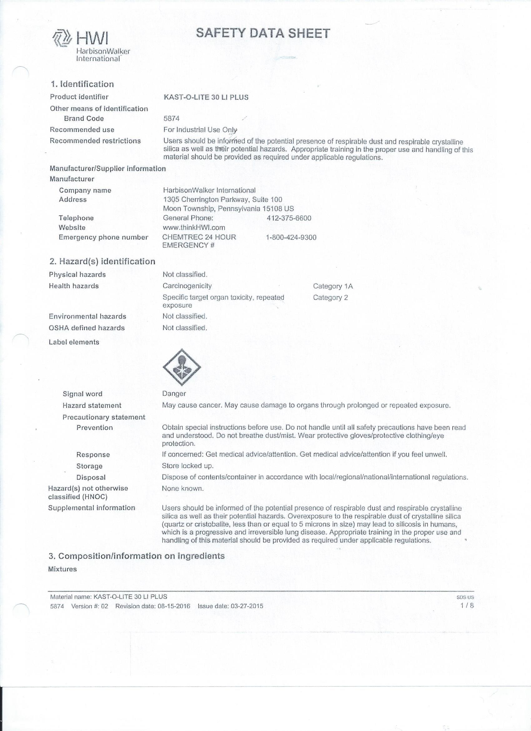
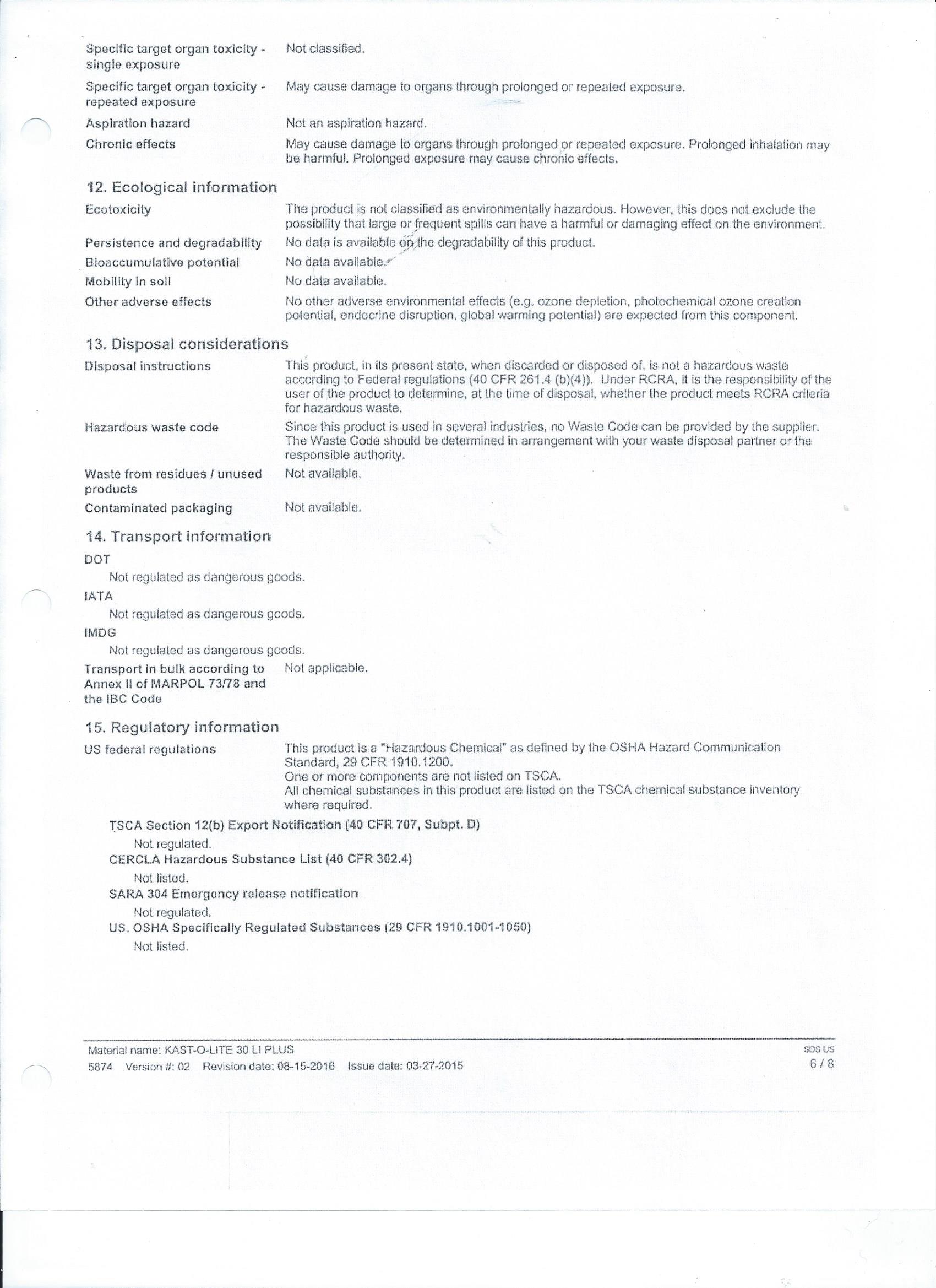
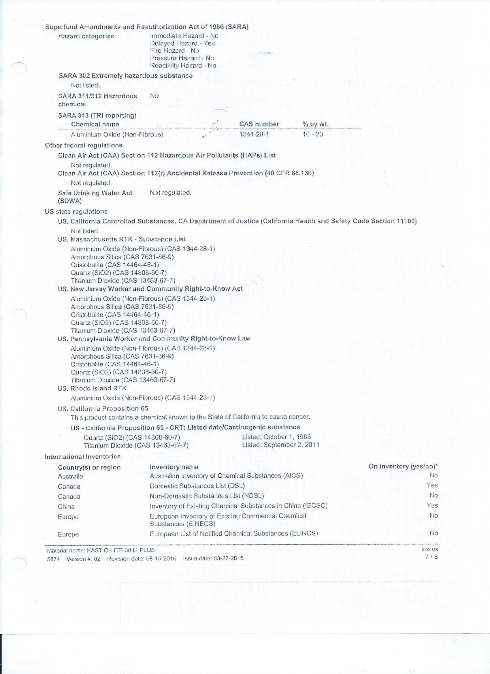
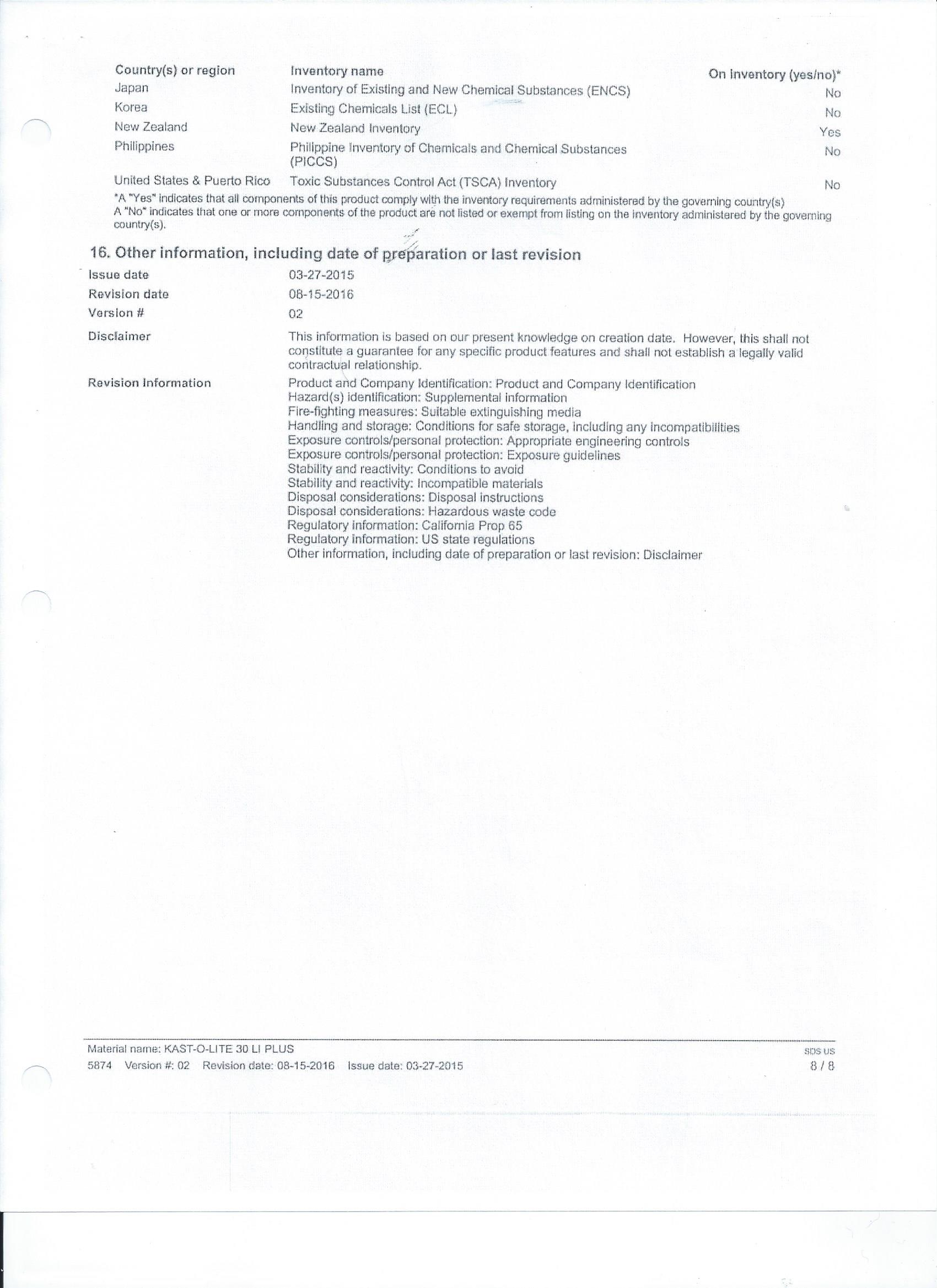
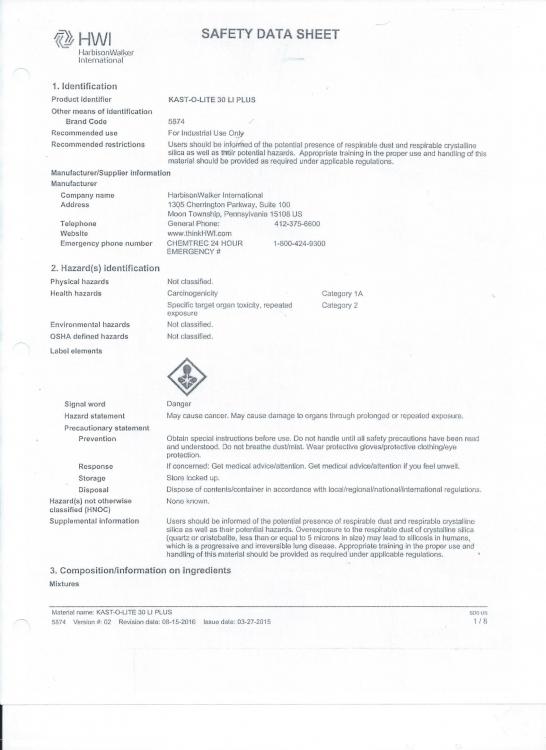
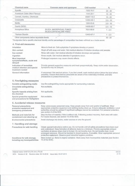
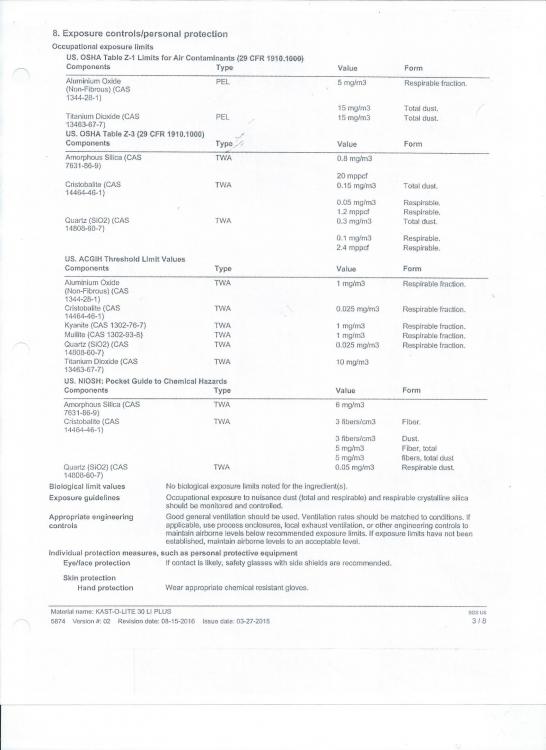
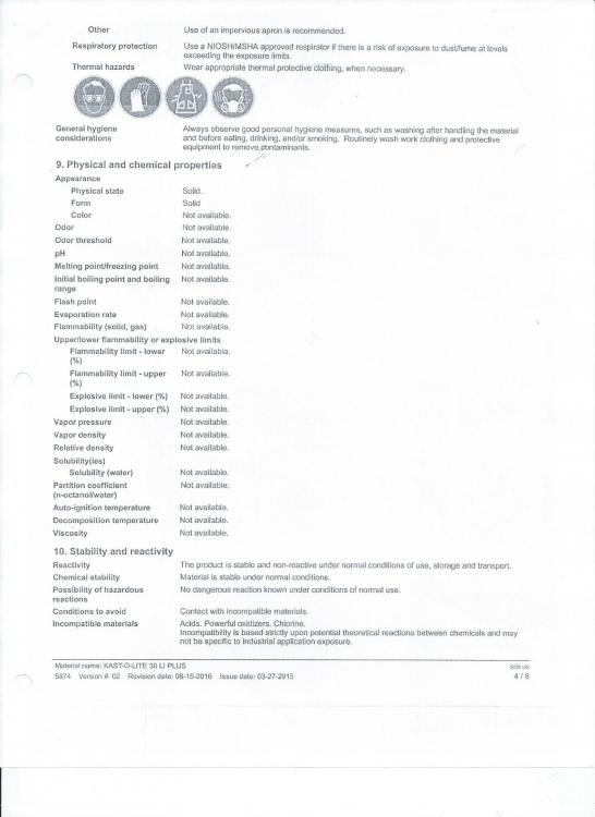
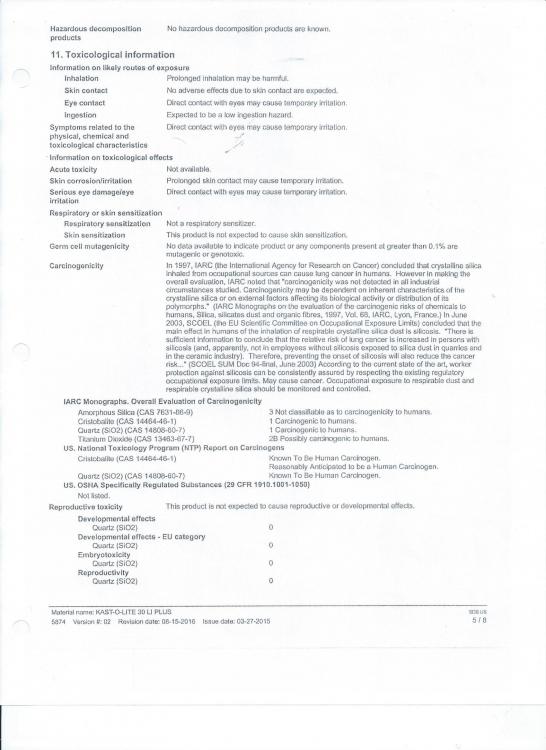
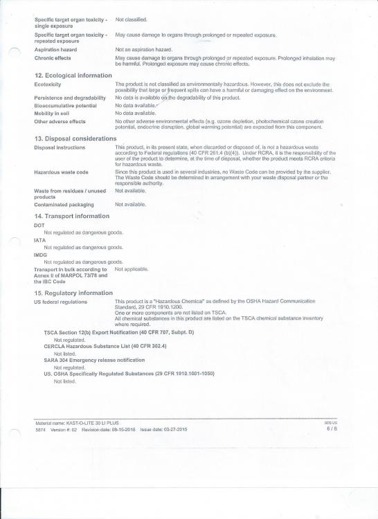
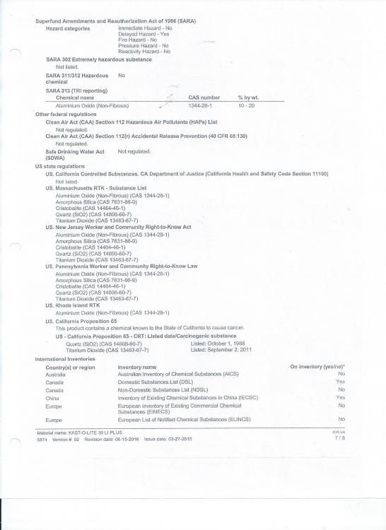
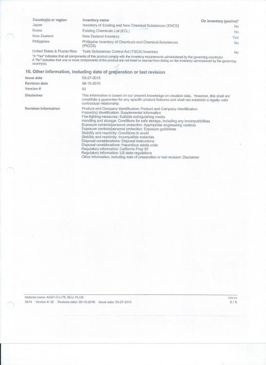
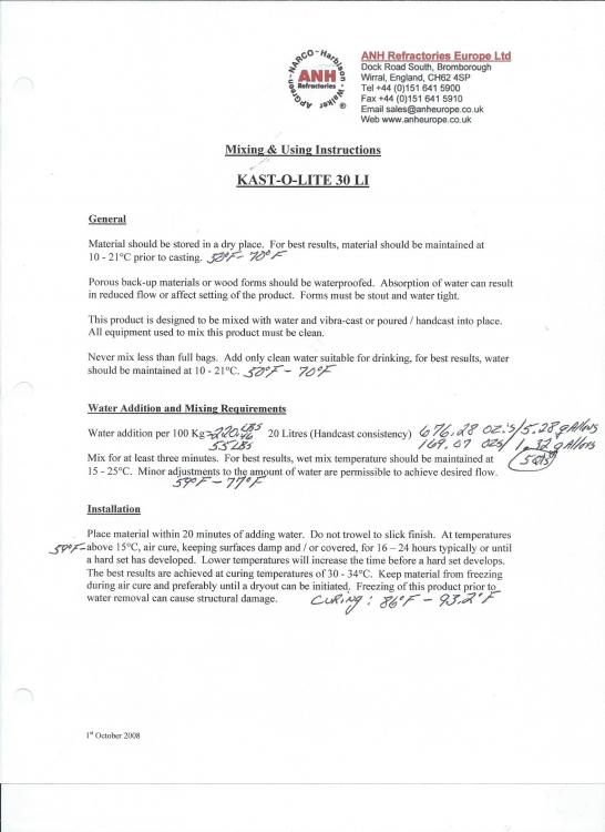
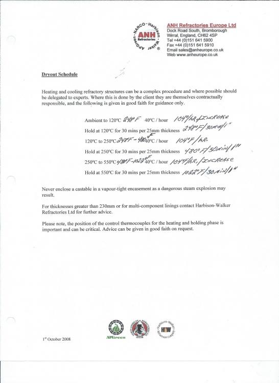
Here's your 1 freebrie. Curing Instructions. Kast-o-Lite 30 Plus MSDS


-
Just before I build my first forge, I need to make sure I have this right
Idk replied to Ethan Yap's topic in Gas Forges
Patience Grasshopper, patience. Suppose to be 1 step forward, not 2 steps backwards. Better safe that sorry. -
Is this "Kitchen Oven" inside your house and the very same oven you use to cook with? If so, DON'T DO THAT!!! Any idea what's in KOL30? Ever heard of a MSDS? Not jumping down your throat but people need to research topics before asking questions they already have access to the answers. Bottom of page for Manufacturer curing instructions. https://www.iforgeiron.com/topic/52885-another-newbie-forge-build/?page=2&tab=comments#comment-598276
-
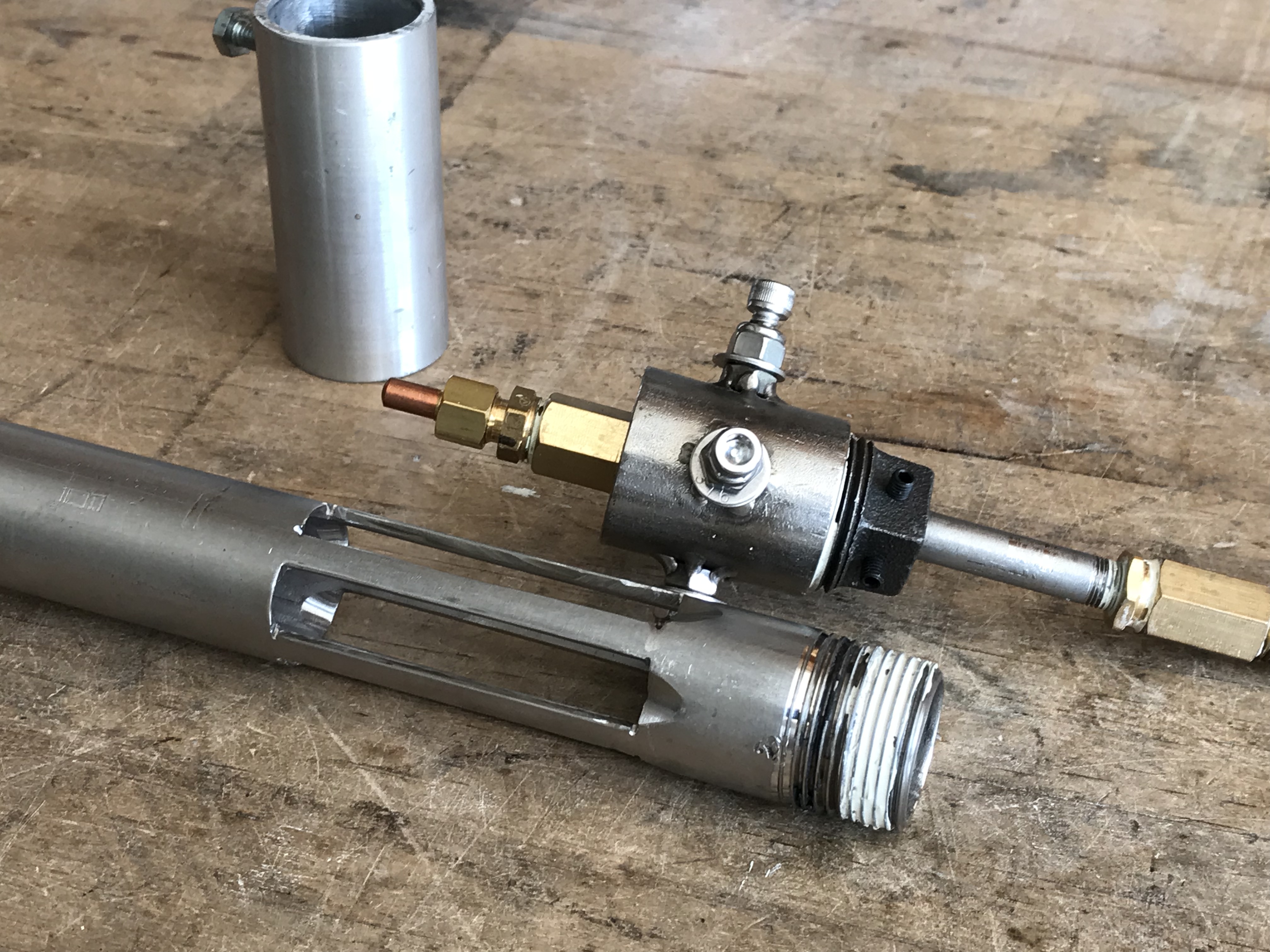
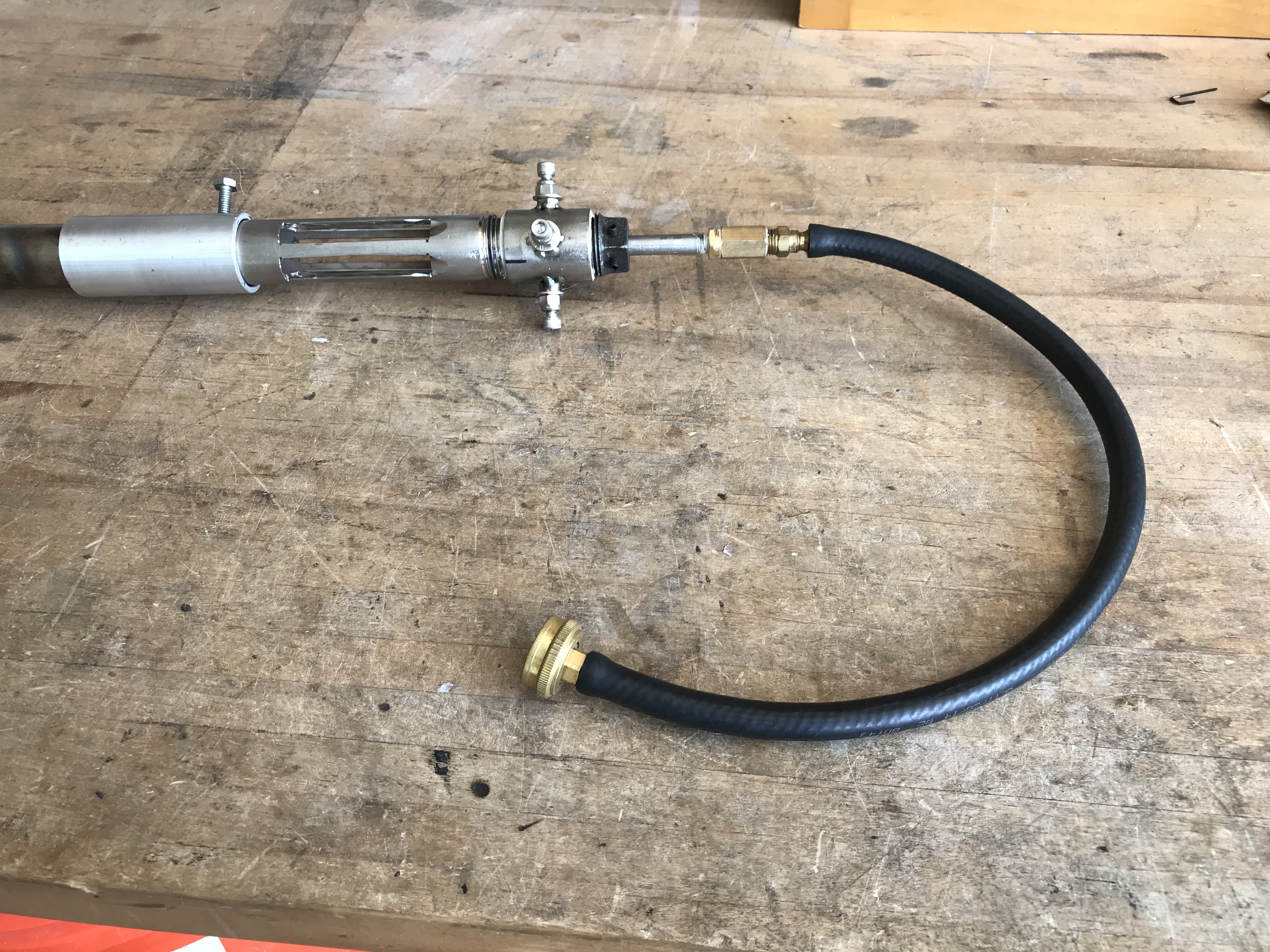
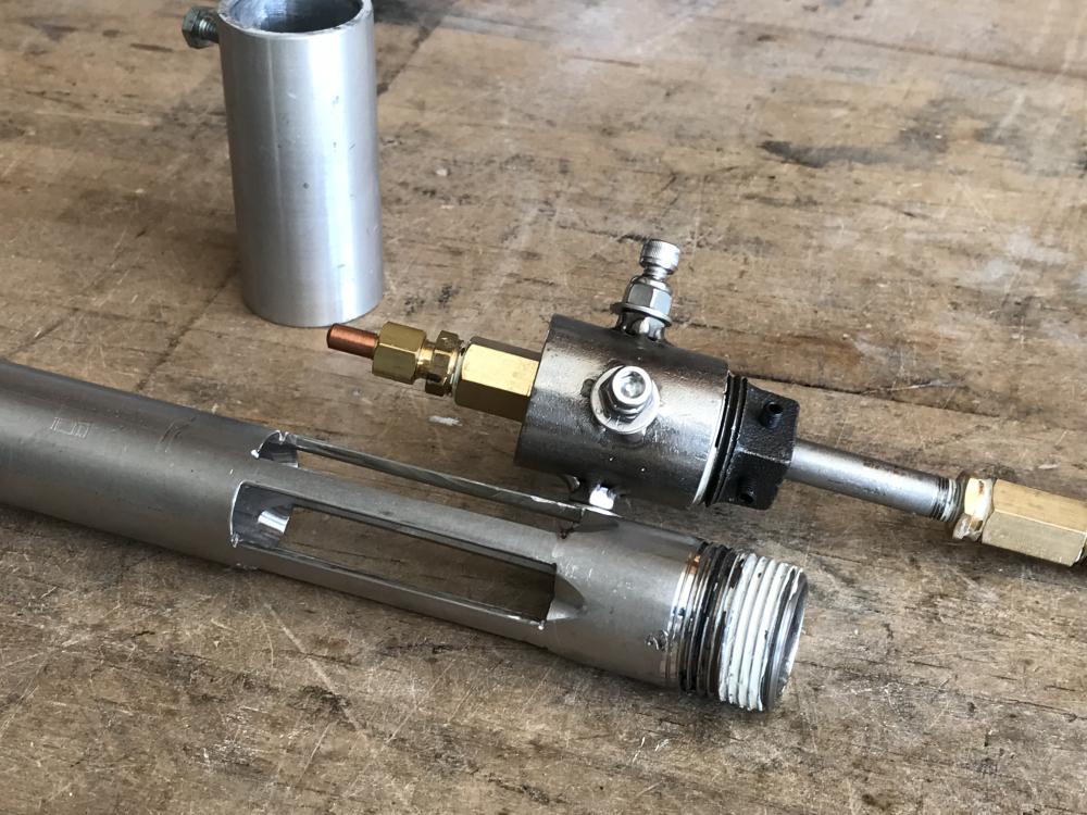
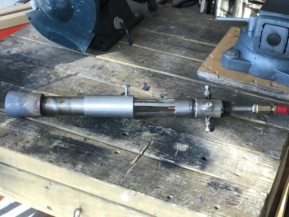
This thread is to assist others in understanding the How’s, Why’s and Results of properly and improperly building and aligning all components of such a build in addition to the proper placement of the burner within the forge burner holder. In no way or form is this thread intended to replace IFI’s Forge 101, Burners 101 or any other threads and the information within those threads which has been made a sticky and it is HIGHLY ADVISED to read any & all of those threads in their entirety for your specific build. This thread, in a nut shell, is basically what I have comprehended from both those threads and other credible information gathered and applied over the last year. I am continuously learning new aspects and facts of the World of Fire each and every day. Disclaimer: In no way or manner shall I be held liable for personal physical injury or property damages resulting from anybody copying in part or whole the build and design of the this burner. If copied in part or whole the builder/user does so SOLEY at their own risk. This is not a One Size Fits All. No 2 burners perform identically. This is just to give a general overview and understanding of what to look for. Basic shop tools were utilized for this build. Dremel, abrasive cutoff wheels, drum sanding barrels, drill press with a properly aligned table to spindle/chuck head, stationary vise, drill bits, taps, TIG welder (optional), angle grinder w/ cutoff disk or a cold cut chop saw, wrenches. NA Mickey Burner The burner’s specs are as follows: Burner Tube: 304L Stainless Steel, schedule 40 ID: 1” Length: 12” CONSTRUCTION There’s 5 air intake ports which are 1/2” x 3” for a total of 7-1/2 square inches of intake. The mixing tube is on the short side of 7-1/8” excluding the nozzle but it works. As Mikey recommends in Burners101 the “mixing tube” side should be around 8”- 9” in length. For clarification, this would be the part of the burner tube beyond the intake ports. Once I figured out what size of intake openings I needed, I taped the pipe off accordingly, sprayed it w/ rattle can paint, removed the necessary masking and proceeded to make my cuts with a dremel and cutoff disks while it was secured within my table vise. Once all cuts were made I took a screw driver and gently pried one end up where I could grasp the cut out with needle nose pliers to finish removing. Do Not pry the cut out sections up by resting the screw drive anywhere but at the ends of the intake ribs to prevent from damaging them. The Fuel jet (Mig tip) is a hit or miss thing and will need to be played with to achieve optimal performance with your particular burner. This particular burner started out with a .045 mig tip for the jet but that was too rich. For some reason I’m thinking the id of a .045 tip is .0625. Tried pulling it up on the net but can’t verify that number. It was replaced with a .035 tip which I drilled out with a #55 (.0520) drill bit. If you do drill these tips out it works best using a drill press and lubricant. I like using a bar of soap to lube the bit. Take your time, bore a little, back out clearing the chamber, repeat, repeat, repeat. That size jet seems to work great for this particular burner, forge construction and my geographical location due to atmospheric pressures, etc. The Mig tip jet is secured with standard ¼” brass plumbing fittings. Safety Tip HIGHLY advised to spray all connections with soapy water PRIOR to striking a flame to the burner to detect any fuel leakage within your configurational setup. As also suggested, a Tapered MIG welding contact tip works best for the burner jet. Another thing to be on the lookout for it where the jet tip is positioned within the burner throat (at the beginning of the air intakes) this also will play a role in how the burner functions. The end of the jet tip should be protruding approximately 3/8” past the back of the intakes for a starting point of fine tuning your burner and it’s operation. Intake Air Ports The fore and aft ends of the intake ports have been beveled as recommended in Burners 101 for a smoother transitional flow intake of air within the mixing tube which reduces/eliminates turbulence for smoother operation. NOTE: The beginning of the intake chamber closest to your jet needs to be beveled on the “outside” tapering into the intake port. The end of the intake chamber farthest from the jet side needs to be beveled on the “inside” creating a funnel. The ribs between the individual intake ports are ¼” wide and have been beveled/tapered as well to reduce turbulence. Anything you can do to eliminate or reduce turbulence is a plus in the design and operation of the burner. Coupler & End Cap Coupler: Holes were drilled and nuts were welded in place. This was the easiest route as SS isn’t the funniest stuff to fabricated compared to mild steel. This procedure can be accomplished by using standard plumbing fittings with drilled and tapped set screw holes. The end cap plug is a standard steel plumbing fitting. Holes drilled, tapped and set screws installed. By fabricating it in this fashion it allows the builder/user to connect a piece of hose and a spigot fitting to the water hose and the fuel rail/pipe nipple which connects to the mig tip/jet setup for proper fuel stream alignment down the center of the mixing tube. Nozzle Originally I attached a SS concentric reducer (1-1/4” to 1-1/2”) which in reality resulted in a 1” id mixing tube diameter to the widest end of the flare which as stated was 1-1/2”. Running @ 8psi the results of such.... If I remember correctly, it is stated that the flame side of the nozzle needs to have a taper of 1 to 12% gradual taper outward. That will need to be verified by the builder within Burners 101. I replaced the above mentioned nozzle with a piece of 316 SS 1-1/4”id straight pipe 2-1/4"L w/ a 2" inner working chamber one attached. It needed to be beveled out on the flame side ever so slightly to stabilize and hold a flame within the forge, I'm going to bevel it out even more when I get around to it. Aligning Burner Jet Stream Unless the burner components were fabricated using a lathe and mill (precisely) the jet stream Will Not be dead centered. Improper jet alignment is a bad thing. Below is the result of a hand fabricated burner with the jet housing just screwed onto the burner mixing tube. Secure the burner in a vise, remove the burner nozzle, connect the jet alignment hose setup with a hose clamp to the fuel jet nipple fitting, turn water on and adjust the jet stream via the set screws until dead center. By removing the nozzle, this will allow the tuner to get the jet stream dead center of the mixing tube. Once the Burner has been aligned the nozzle can be reattached and centered per the jet stream. Methodically and gently tighten the set screws snuggly but not so tight to disturb the alignment and your good to go. As mentioned in Burners 101 this aspect is critical in the proper function of any NA burner. Testing Outside the Forge This particular burner will not hold a flame outside the forge yet has no problem firing up and holding a stabilized flame within the forge. Why is this? Outside the forge it lacks back pressure to hold a stabilized flame in the nozzle. I also suspect this issue is due to the lack of taper travel into the nozzle. So, just because it won’t hold a flame outside the forge doesn’t necessarily mean it won’t work inside the forge. Test & Tune accordingly. Burner Holder & Burner Placement Within 2” id schedule 40 mild steel pipe was used for the holders which serves multiple functions. I designed my forge to accommodate and utilize a single burner or multiple burners depending on the job. Secondly, such a design also allows different sized burners to be used in the arranged holder ports. Thirdly, It allows the operator to fine tune the air intake or restriction of air flow into the chamber wherefore regulating such and the ability to create a reducing, neutral or oxidizing atmospheric state. Fourthly, It allows adjustment of the burner flame direction placement. Lastly, any of the un-operational Burner holder ports can be used as a chimney. When using a hard castable refractory as an inner shell the section of the holders which will be passing through the shell should have a few slots cut into them for expansion purposes to prevent cracking of the inner hard shell. I chose to wallow out the passages of the hard refractory where the burner port holders went for final adjustment of the holder position prior to welding them in place. This also created an expansion allowance for the holders to expand and not crack the inner shell. The burner holder’s inner port opening closest to the inner chamber should be slightly beveled to eliminate any burrs or lips which will create turbulence or disrupt a properly tuned flame entering the forge's chamber. It is also advised the burner holder(s) need to be positioned as to not allow the holders end(s) to enter the forge’s chamber walls to prevent melt down. The burner nozzle(s) should be placed within the burner holders approximately 1/4" 1/2” pulled back from the end of the holders to further prevent nozzle melt downs. Hence, the reason for beveling and removing any obstruction(s) (burrs or lips) from inside of the burner holder on the flame end. Again, anything and everything which results in a smoother transitional air flow or flame path should be done to achieve maximum performance. I haven’t done the deburring of my inner burner ports as of this posting and as a result it can be seen within the flames contoured shape. Running @ 8psi. 12 PSI
-
Video link no worky. Good to hear they’re improving.
-
Straight from the horse's mouth.
-
While burners act differently depending on geographical location due to atmospheric pressure, a .035 tip is going to run rich for a 3/4” burner. Forge design along with it’s chamber pressures will also affect the burners function as well. I’m located in Florida and only run a .025 in my 3/4” burner but that’s in a furnace. I tried it in the forge the other evening and had to really crank it up to keep a flame going. Once I closed the forge door it stayed lit. Me also thinks that flare nozzle is on the long side also. I know the ones sold on line are only 3”OAL, subtract 1/2” for attachment and you end up with a 2-1/2” working chamber within the nozzle. But like I said, you’ll just have to play with it and modify accordingly. Food for thought. So many little factors. It’s a quick easy change out so have fun playing with it. I’d run down to Harbor Freight and pick up one of their multi tip packs so you have a variety on hand. Keep us posted and don’t forget pics.
-
Guess I should explain the “Why’s” of the construction behind the burner. First off it’s a 1” id burner. Secondly, the flare nozzle flame side is 1-1/2” where as for optimal performance and from what I’ve gathered from Burners 101 should be 1-1/4” id flame side. It was originally built for my furnace so the nozzle wasn’t in the picture until recently and that’s the only concentrical reducer I had on hand. Overall length is 12”. There’s 5 air intake ports which are 1/2” x 3” for a total of 7-1/2 square inches of intake. The mixing tube is on the short side of 7-1/8” excluding the nozzle but it works. As Mikey suggests I’m Burners101 the mixing tube side should be around 8”-9”. For clarification, this would be the part of the mixing tube beyond the intake ports. Originally it had a .045 mig tip for the jet but that was too rich. For some reason I’m thinking the id of a .045 tip is .0625. Just tried pulling it up in the net but can’t verify that number. It was replaced with a .035 which I drilled out with a #55 (.0520). That seems to be the sweet spot for it as I no long smell any carbon monoxide. I did go out to the shop this morning and pertain to beveling the intake ports as recommended for a smoother flow and alleviate turbulence. Mike, zoom in on the attached photos to see what I’m referring to about the be beveling. The ribs between the individuals intake ports are beveled/tapered as well. To the end cap & coupler fitting with the set screws. Coupler, holes were drilled and nuts were welded in place. This was the easiest route as SS isn’t the funniest stuff to fabricated compared to mild steel. The end cap plug is a standard steel plumbing fitting. Holes drilled, tapped and set screws installed. By fabricating it in this fashion allows me to connect a piece of hose and a spigot fitting to the water hose and the fuel rail/pipe nipple which connects to the mig tip/jet setup. Secure the burner in a vise, turn water on and adjust the jet stream via the set screws until dead center. Methodically and gently tighten the set screws not to disturb the alignment and your good to go. As mentioned in Burners 101 this aspect is critical in the proper function of any NA burner. Improper jet alignment is a bad thing. This post is not intended to highjack Mike’s thread but to answer Mikey and try to help Mike understand the aspects of building a proficient Mickey burner. I’ll snap a shot of the burner in action tonight once it gets dark.

-
With all due respect for Mr. Mike a picture is worth a thousand words. Here’s how I build my Mikey burners.
-
Welcome aboard Mike. Oh Mr. Mike is going to have fun with this one. Might I recommend reading Burners 101. It covers and thoroughly discusses just about everything to do with NA burners. https://www.iforgeiron.com/topic/46536-burners-101/ Mr. Mike’s post entry #26 on page 6 of Burners 101 addresses the design of your burners. Also suggest you definitely read it as well. I like the Mikey burners (personal preference) for my application(s) due the ease of fine tuning.
-
Everything within reason, common sense and application is subject to users discretion. I was only pointing out what manufacturer suggested. JlBlom pointed out it doesn’t take as much water as one would think and rightfully so. Which brings up an important aspect of Not adding to much water which anybody that has ever used KOL knows there’s a thin line between not enough, just enough water, enough or too much. I was playing around with some KOL a couple weeks ago. Sifted some with standard window screen to remove all the big stuff, mixed with 50/50 commercial rigidizer & water. I brushed it on the inner wall(s) of the forge KOL hot face shell to fill in any voids/air pocket holes due to the casting. Adhered just fine although left a somewhat rough finish due to the larger granulars of refractory elements left behind after sifting. What i noticed after mixing was the collodial silicate mixed with the sifted KOL began to thicken shortly afterwards so the work time will be limited to around 10 or so minutes for application. Was just experimenting to find a cheaper brushable alternative for a CFB wash or KOL shell repair. Checked the inner shell today and seemed to hold up fine from last nights initial firing. Again, everything subject to application and users discretion.
-
Correct TP. 8 oz = cup 16 oz = pint 32 oz = quart 128 oz = gallon Curious but did I post something to indicate there was 10 pints to a gallon? <shrug?> Actually, for only 5 lb.’s of KOL he would need 13.33 oz’s of water, per manufacture recommendations.
-
Per manufacturer instructions it requires just over a gallon of water per 55 lbs. So, for 5 lb.’s, that would be right at 16oz’s of water. I’d only add 10-12oz,’s to start. Put some rubber gloves on and mix by hand thoroughly. Add the remaining 4-6 oz’s as needed. I stop adding water of the required amount once the KOL achieves a compressible form by hand. Holds together without falling apart. If you going to trowel on a 1/2” layer you’ll more than likely need the full amount of water required. Once it’s set up for 12-16 hours, pritz it w/ a spray bottle of water. I always let the stuff sit up for a few days after casting and unwrapping to allow whatever moisture still in it evaporate before firing. Just treat it like you would concrete. Per manufactures recommendations: It’s not to be cured out any faster than 104* for certain specified amounts of time but as long as you take it slow and easy you should be fine without any cracking developing. Side Note: KOL can be sanded and polished to a smooth finish if desired. Make sure you wear a respirator and do it outside with a good strong fan blowing the dust away from you and your shop.
-
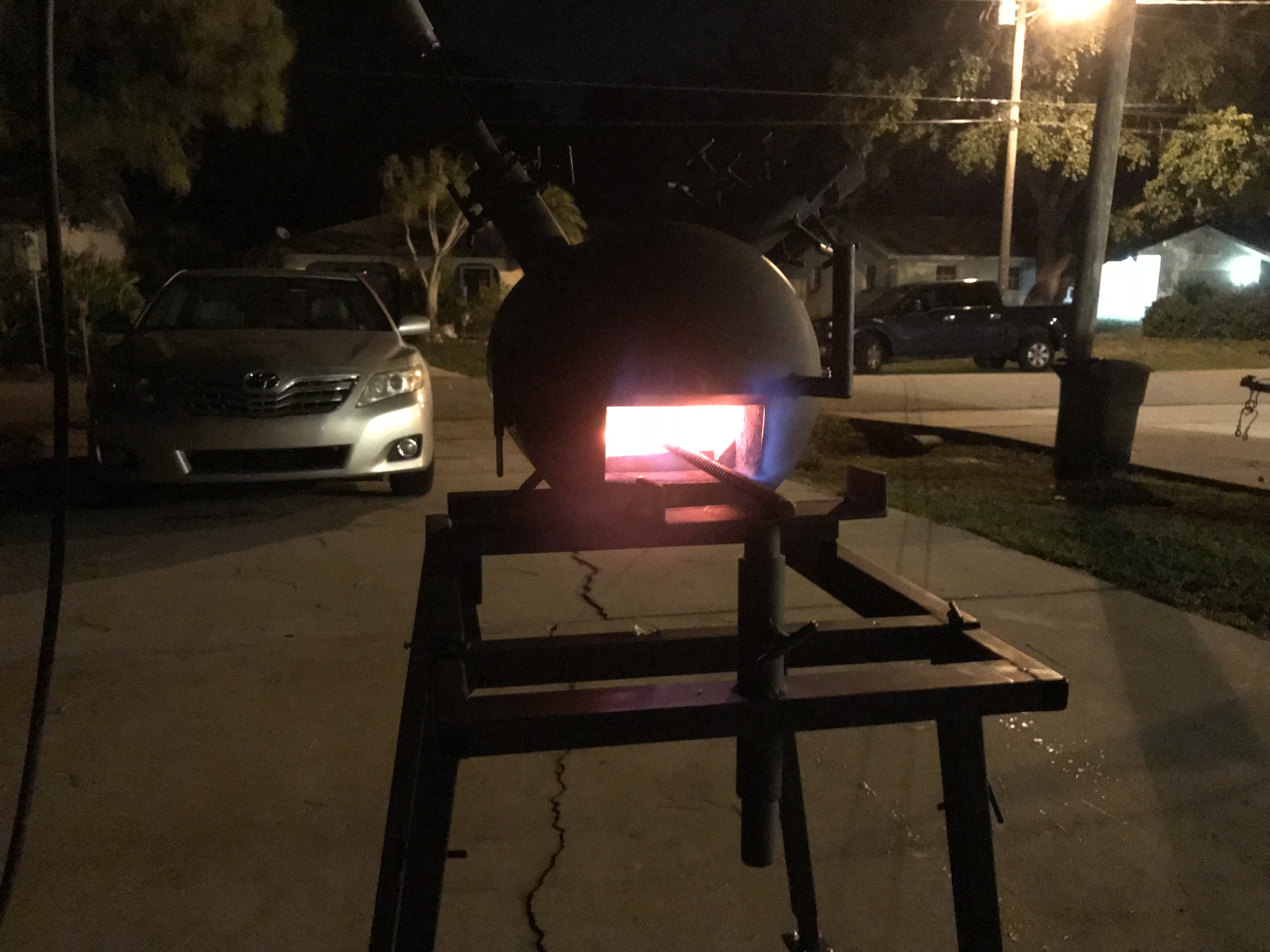
Well Gents, waiting on SS supplies to build my burners for the forge and just couldn’t resist so I stuck the very first 3/4” Mickey burner I ever built in it tonight and here she is. Had to pull the thermocouple probe out at 2100* because I didn’t want it to end up in a puddle. Can only imagine the temps it’ll hit with (2) 3/4” burners in it.